Download Manual - Specto Technology
Transcript
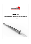
MEXID MINIATURE BOREHOLE EXTENSOMETER User’s Manual MEXID miniature borehole extensometer INDEX Description Pag. 4 Preliminary checks Pag. 5 Installation Pag. 5 Wiring Pag. 8 Taking measurements Pag. 9 Data processing Pag. 9 Troubleshooting Pag. 10 Maintenance Pag. 11 Appendix 1 Pag. 12 Information contained herein are property of SISGEO S.r.l. This document is subject to change without notification and is subject to be returned upon request. No part of this User’s Manual may be reproduced in any form without SISGEO’s S.r.l. written permission. SISGEO S.r.l. Mexid EN 00/11 Page 2 of 12 MEXID miniature borehole extensometer Notes on the use of product For a safe and efficient use of the product, please read carefully the following instructions before starting any operation. Any use of the product other then the one described in this manual shall be considered at user’s full responsibility. The same applies for any unauthorized modifications. In addition to the hereby listed standards, the user must comply with the provisions of the current legislation on the matter of personal safety and health of persons in the workplace. SISGEO is not responsible for any trouble, breakdowns, accidents etc.. due to the lack of knowledge and/or confidence (or non-compliance with) with the requirements contained in this manual. Check that the product has not been damaged during the transport. Verify that the package includes all items as well as any requested optional accessories; if anything is missing, please promptly contact the manufacturer. The user must strictly follow all the operations described in this manual. Maintenance or repair of the device is allowed only to authorized operators. These operators must be physically and intellectually suitable. For information about instrument or order spare parts request, please always specify data written on the identification label. When replacing parts, always use ORIGINAL SPARE PARTS. The manufacturer reserves the right to make changes without prior notice for any technical or commercial requests. We’ll try anyway to keep the manuals updated in order to reflect product’s revisions/updates. Disposal According to the European Standard 2002/96/CE, the device must be disposed in a proper manner. The recyclable materials within the device shall be collected by the user, in order to avoid the environmental pollution. For further information, please contact your dealer or local waste disposal service. This product must be disposed in a collection point for electronic components recycling. Incorrect disposal by the user could be subject to fines. Symbols Below are the symbols used to catch reader’s attention on the manual: Warning! These operation must be performed from specialized personnel! Pay particular attention to the following instruction. Identification SISGEO S.r.l. Instruments can be identified From a production lot number (written on the Compliance Certificate) From a serial number (s/n) engraved indelibly on the instrument From a label on the instrument From a label on the cable Mexid EN 00/11 Page 3 of 12 MEXID miniature borehole extensometer Description MEXID is a small diameter electric transducers’ multi-rod extensometer for application in stable and open boreholes. The system consists of: multirod head assembly (50mm OD) equipped with 2, 3 or 4 linear built-in displacement transducers (DTE) and multicore cable, fibre-glass measuring rods with nylon sleeve, groutable anchors. MEXID is fully preassembled at factory with the measuring rods supplied at the fixed lengths. The longest rod is identified as #1, the other rods are numbered clockwise by decreasing lengths. Both vibrating wire (VW) and linear potentiometer (LP) transducers (DTE) are available with 50mm and 150mm range pre-set at 50% of the full scale. Grouting tube is supplied separately. fixing plate Multirod transducer assembly grouting tube fiberglass rod with protection sleeve fiberglass rod with protection sleeve fixing plate bottom anchor bottom anchor SISGEO S.r.l. Mexid EN 00/11 Page 4 of 12 MEXID miniature borehole extensometer Preliminary checks MEXID shall be installed in a stable and open borehole. The use of a temporary protection casing is possible but very delicate because the system has to be fixed/set at the surface. Suitable diameter is BQ borehole size (46/55mm). For the first meter the borehole shall be enlarged up to 75mm since the grouting tubes will be used. Before starting installation is recommended to: check the integrity of the instrument and if all the components have been delivered correctly; take control readings by portable readout (i.e. CRD400). Useful tools (metric): Allen keys n° 3, 4, 6 Spanner n° 20, 24, 46 Wrench n° 10 Installation Phase 1: Grouting Grouting tubes (orange) are supplied separately. The two grouting tubes shall be cut to the desired lengths: the shorter shall be approx 1.5m long; the longest 2m over the longest rod. Fix the longest grouting tube to the rod with adhesive tape. Rod Transducer assembly Grouting tubes Fixing plate Seal borehole to avoid grout leakage SISGEO S.r.l. Mexid EN 00/11 Page 5 of 12 MEXID miniature borehole extensometer Upward installation Rods Transducer assembly Seal borehole to avoid grout leakage Once the grouting is ended, cut and seal the grouting tubes Grouting tubes Phase 2 : Release of the transducer assembly MEXID is supplied with the transducers “blocked” in order to prevent rod movements during grouting. In order to “unlock” the transducers follow the sequence 1 to 7. 1 2 Fixing plate Once the grout hardened, remove the fixing plate unscrewing the three screws with allen key nr.4 SISGEO S.r.l. Mexid EN 00/11 Release the cable gland (1) with the spanner nr.20 or 24 and unscrew the threaded cap (2) using the spanner nr. 46. Warning: don’t twist the cable. Page 6 of 12 MEXID miniature borehole extensometer Remove the M6 nut using the wrench n.10 Extract the plate removing the two screws with allen key nr.3 Turn the threaded rod by wrench nr. 10 counterclockwise and remove it. Once extracted the threaded rod, lock the M8x12 screw with the bonded washer - supplied with MEXID separately - for waterproofing. SISGEO S.r.l. Mexid EN 00/11 Page 7 of 12 MEXID miniature borehole extensometer Close MEXID screwing the threaded cap, fix plate by screws and tight the cable gland. Wiring MEXID is available with: Vibrating wire transducer assembly (VW DTE assembly) Linear potentiometer transducer assembly (LP DTE assembly) Herewith follows the wiring scheme for both VW and LP (4-20mA current loop) assembly for 2-fold DTE, 3-fold DTE and 4-fold DTE assembly: 2-FOLD DTE ASSEMBLY Function Rod #1 Rod #2 VW / +Loop Red Yellow VW / -Loop Black Blue Thermistor Temp. White Temp. Green 3-FOLD DTE ASSEMBLY Rod #1 Rod #2 Rod #3 VW / +Loop Red Black Brown VW / -Loop Red-white Black-white Brown-white Thermistor Temp. Green Temp. Green-white Temp. (spare) Blue Temp. (spare) Blue-white 4-FOLD DTE ASSEMBLY Rod #1 Rod #2 Rod #3 Rod #4 VW / +Loop Red Black Brown Yellow VW / -Loop Red-white Black-white Brown-white Yellow-White Thermistor Temp. Green Temp. Green-white Temp. (spare) Blue Temp. (spare) Blue-white 3-fold and 4-fold DTE assembly are equipped with two thermistors, one of them considered as a spare. SISGEO S.r.l. Mexid EN 00/11 Page 8 of 12 MEXID miniature borehole extensometer Taking measurements Manual measurements are carried out by portable readout (i.e. SISGEO CRD-400, New Leonardo) connecting the cable wires to the readout flying cable clips. Please refer to the above wiring scheme and readout manual for wiring instructions. MEXID allows automatic measurements by means of SISGEO ADK-100 data acquisition system or any other suitable datalogger. Please refer to the above wiring scheme for wiring instructions. For further information please refer to readout and/or ADK-100 user manual. Data processing The following formulas allow to convert the electric measurements into engineer values: Linear factor Polynomial factors Leng = Lelec/S [mm] Leng = (Lelec2 x A) + (Lelec x B) + C [mm] Leng = engineering reading Lelec = electric reading S = sensitivity factor A, B, C = polynomial conversion factors S, A, B, C factors are stated on DTE Calibration Report With regard to the measuring range (rod position) of DTE transducers herewith follows the table with the nominal values for both VW and LP DTEs: Nominal values DTE rod position VW LP Max extension 9000Dg 4mA Max compression 2500Dg 20mA The exercise readings refer to the initial reading (zero reading). L i - L0 L0 = Zero reading Li = Exercise reading Zero reading shall be taken carefully once the installation is performed and the instrument is in operating conditions. Example LP DTE range 50mm (mA readings) S = 0.32051 mA/mm A = -6.984 E-04 , B = 3.137 E+00 , C = -1.264 E+01 L0 = 12.050 mA , L1 = 16.048 mA (L1 > Lo Compression) Using: Linear factor (L1-L0)/S : (16.048 – 12.050)/0.32051 = 12.47mm Polynomial Factor [(L12 x A)+(L1x B)+C] – [(L02 x A)+(L0x B)+C]= 37.522–25.0590=12.46mm Temperature Reading Using readout units such as SISGEO CRD-400, New Leonardo, temperature will be displayed directly in °C (degrees Celsius); if the resistance value is read, the conversion formula or the table in Appendix 1 can be used. SISGEO S.r.l. Mexid EN 00/11 Page 9 of 12 MEXID miniature borehole extensometer MEXID is a fully assembled instrument and DTE replacement/maintenance is not allowed. Checks of malfunctioning are limited to the following: LP DTE VW DTE TRANSDUCER Troubleshooting Maintenance Problem Possible cause Solution Measure not stable DTE shaft out of range Cable shield not connected Electromagnetic fields generated by engines, generator, antennas, welders or high voltage lines nearby Datalogger grounding not well done Cable cut None Connect the shield Identify and remove the cause. Shield the signal cable. Cable damaged Wiring not correct Measure VW (coil) resistance by portable Ohmmeter. Acceptable values are in the range of 150Ω±15%. Make proper wiring Measure not stable Wiring not correct Make proper wiring Measure 0 mA Wiring not correct Make proper wiring Measure over range Wiring not correct Make proper wiring Wire not detected Provide efficient grounding Repair the cable. Cable splicing kit available at SISGEO. After-sales assistance for calibrations, maintenance and repairs, is performed by Sisgeo’s service department. The authorization of shipment shall be activated by RMA “Return Manufacturer Authorization". Fill in the RMA module clicking on: http://www.sisgeo.com/en/assistance/repairs/ Send back the instrument/equipment with the complete accessories, using suitable packaging, or, even better, the original ones. The shipping costs shall be covered by the sender. Please return to the following address with suitable delivery document: SISGEO S.r.l. Via F.Serpero, 4/F1 20060 MASATE (MI) On the delivery document is mandatory to indicate the RMA code received. Technical assistance e-mail: [email protected] SISGEO S.r.l. Mexid EN 00/11 Page 10 of 12 MEXID miniature borehole extensometer Appendix 1 THERMISTOR TEMPERATURE CONVERSION Resistance to temperature equation: T 1 273.2 3 A BLnR C LnR Where: T= temperature in °C LnR= natural Log of the thermistor resistance A= 1.4051x10⁻³ (coefficents calculated over the -50 to +70°C span) B= 2.369x10⁻⁴ C=1.019x10⁻⁷ SISGEO S.r.l. Ohms Temp Ohms Temp Ohms Temp Ohms Temp 16.60K -10 5971 10 2417 30 1081 50 15.72K -9 5692 11 2317 31 1040 51 14.90K -8 5427 12 2221 32 1002 52 14.12K -7 5177 13 2130 33 965.0 53 13.39K -6 4939 14 2042 34 929.6 54 12.70K -5 4714 15 1959 35 895.8 55 12.05K -4 4500 16 1880 36 863.3 56 11.44K -3 4297 17 1805 37 832.2 57 10.86K -2 4105 18 1733 38 802.3 58 10.31K -1 3922 19 1664 39 773.7 59 9796 0 3784 20 1598 40 746.3 60 9310 -1 3583 21 1535 41 719.9 61 8851 2 3426 22 1475 42 694.7 62 8417 3 3277 23 1418 43 670.4 63 8006 4 3135 24 1363 44 647.1 64 7618 5 3000 25 1310 45 624.7 65 7252 6 2872 26 1260 46 603.3 66 6905 7 2750 27 1212 47 582.6 67 6576 8 2633 28 1167 48 562.8 68 6265 9 2523 29 1123 49 543.7 69 525.4 70 Mexid EN 00/11 Page 11 of 12 MEXID miniature borehole extensometer Appendix 2 V/V LP DTE ASSEMBLY DTE assembly equipped with Linear Potentiometer having V/V signal output. Wiring 2-FOLD DTE ASSEMBLY Function Rod #1 + Vcc Red Rod #2 White Signal Blue Yellow GND Black Green Function Rod #1 Rod #2 Rod#3 + Vcc Red Black Brown Signal Red-White Black-White Brown-White GND Blue Yellow Grey Function Rod #1 Rod #2 Rod#3 Rod #4 + Vcc Red Black Brown Yellow Signal Red-White Black-White Brown-White Yellow-White GND Blue Yellow Grey Pink 3-FOLD DTE ASSEMBLY 4-FOLD DTE ASSEMBLY For manual readings use CRD-400 only with V/V LP interface. Please select “voltage” on main menu. Connect the clips (A,B,C) to the colored cable wires as reported in the following table: 2-FOLD DTE ASSEMBLY CRD-400 clips Rod #1 Rod #2 A Red White C Blue Yellow B Black Green 3-FOLD DTE ASSEMBLY CRD-400 clips Rod #1 Rod #2 A Red Black Brown C Red-White Black-White Brown-White B Blue Yellow Grey CRD-400 clips Rod #1 Rod#3 4-FOLD DTE ASSEMBLY SISGEO S.r.l. Rod #2 Rod#3 Rod #4 A Red Black Brown Yellow C Red-White Black-White Brown-White Yellow-White B Blue Yellow Grey Pink Mexid EN 00/11 Page 12 of 12


