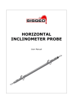
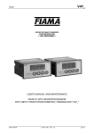
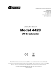
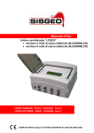
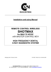
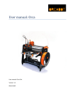
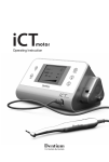
1
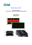
USB WIRE CRACKMETER
USER’S MANUAL AND MAINTENANCE
Rev.0 -07.11.2011-
1 |Page
INDEX
NOTE OF SYSTEM UTILIZATION
Pag.3
MANUAL PURPOSE
Pag.4
ENVIROMENTAL CONDITIONS
Pag.4
CONFORMITY DECLARATION AND EC MARKING
Pag.4
MAINTENANCE
Pag.4
WASTE DISPOSAL
Pag.5
SIMBOLOGY
Pag.5
IDENTIFICATION PLATE
Pag.5
USB WIRE CRACKMETER OVERVIEW
Pag.6
DESCRIPTION
Pag.6
DIMENSION
Pag.6
INSTALLATION AND SETTING
Pag.7
POWER SUPPLY
Pag.7
BATTERY CHANGE
Pag.7
USB CONNECTION TO A PC
Pag.8
“WRCDATA SOFTWARE MANAGEMENT” INSTALLATION GUIDE
Pag.9
“WRCDATA SOFTWARE MANAGEMENT” USER GUIDE
Pag.13
DEVICE
Pag.14
POSITION
Pag.14
LOGGING SETUP
Pag.14
DOWNLOAD DATA
Pag.15
SAVE FILE FORMAT
Pag.15
TECHNICAL SPECIFICATIONS
Pag.16
ASSISTANCE
Pag.17
REPAIRS AND MAINTENANCES
Pag.17
PHONE ASSISTANCE
Pag.17
TECHNICAL ASSISTANCE ON SITE FOR SUPPLIED INSTRUMENTATIONS
Pag.17
TRAINING
Pag.17
Rev.0 -07.11.2011-
2 |Page
NOTE OF SYSTEM UTILIZATION
To ensure a safe and efficient functioning, please read the following
instructions carefully before use.
Any unauthorized modification is considered a total responsibility of the user.
In addition to the standards listed above, the user must comply with the existing legislation on safety and
health of employees in the workplace.
Check the product for damages caused by transport.
Verify that your package includes all standard accessories and any accessories required. In case, contact
the manufacturer.
The use of the equipment shall be done only after the proper connection and following the configuration
needed; so the user must carefully perform all the operations described herein.
SISGEO will not be liable for inconveniences, damages, accidents, etc.. due to lack of knowledge (or nonapplication) of the requirements contained in this manual.
The use, any possible maintenance or repair of the equipment is allowed only to skilled and authorized
operators. These operators must be physically, professionally and intellectually capable.
For information or orders of spare parts always specify the data reported on the identification plate
showing the serial number inside each device.
When replacing parts, use only ORIGINAL SPARE PARTS. The use of unoriginal SISGEO spare parts may
cause irregular functioning and dangers for people and objects
The product is not fit for installation in small and/or unventilated environments, with a high humidity range
or in presence of inflammable or explosive liquids. All the instruments and the equipment furnished are not
suitable for installation in potential dangerous area or when the use of explosion-proof components is
foreseen.
The electrical connections must be executed by a qualified installer, observing the effective regulations.
The manufacturer reserves the right to make changes, in case of any manufacturing or commercial need,
without notice.
It will attempt to ensure that user manuals are updated in order to reflect functional product revisions.
Rev.0 -07.11.2011-
3 |Page
MANUAL PURPOSE
This manual has been designed by the Manufacturer to provide the necessary information regarding the
device to those who are authorized to carry out safely its installation, maintenance, dismantling and
disposal.
Other than adopting good technical construction methods, the information should be read carefully and
strictly applied. Inobservance of this information could cause risks for the health and safety of people and
economical damage. This manual reflects the state of skill of the instrument at the time of input on the
market: however the manufacturer reserves the right to make changes, add or improve the manual
without giving any reason to hold the present manual inadequate.
ENVIROMENTAL CONDITIONS
Temperature setting: min. -10°C, max. + 60°C.
It is forbidden to use the instrument other than its specific use and in potentially explosive conditions or
where anti-explosive elements are used.
CONFORMITY DECLARATION AND EC MARKING
The instrument answers to the following Communitarian Directives:
2004/108/EC Electromagnetic compatibility, with reference to general Rules EN61000-6-2 (immunity in
industrial environment) and EN50081-1 (emission in residential environment).
MAINTENANCE
The instrument does not needs a particular maintenance except cleaning to do only with a soft cloth
dampen with ethylic alcohol or water. Do not use hydrocarbon solvents (petrol, diluents, etc.): the using of
these products could affect the proper functioning of the instrument.
Rev.0 -07.11.2011-
4 |Page
WASTE DISPOSAL
According to the European standard 2002/96/CE, the disused instrument must be
disposed in a correct way. The recyclable materials are recovered, in order to avoid the
environmental damage.
For more information please contact your waste disposal service or the instrument
retailer.
SIMBOLOGY
Here are the symbols used in this manual to alert the reader:
Attention! This operation must be executed only by specialized personnel.
Pay particular attention to the following information.
IDENTIFICATION PLATE
Each USB Wire Crackmeter (0D314FV8000) has one identification plate.
This reports the product registration Serial Number.
It is important to communicate this information when requesting information concerning
the product.
Rev.0 -07.11.2011-
5 |Page
USB WIRE CRACKMETER OVERVIEW
Mini USB connector
Stainless steel wire
SISGEO instrument code
DESCRIPTION
Crackmeter with data logger fully independent for the storage of the displacement and temperature. They
are made of a precision rotating potentiometer operated by the means of a winding or unwinding of
stainless steel wire.
Special features of the crackmeter are the simplicity of setting and the limited eye-catching.
They are suitable for monitoring of crack evolution in buildings, geomechanics, and joints. Stroke 80 mm.
Power supply is internal with battery and it may be connected to a PC with a mini USB cable for setting
and for data saving.
DIMENSION
Rev.0 -07.11.2011-
6 |Page
INSTALLATION AND SETTING
The crackmeter has to be mounted on a flat surface and has to be fixed across the fracture to be
monitored. Place, if possible, the case of the instrument in a higher position as to the wire ends. The two
fixing bores allow an easy and quick installation of the crackmeter.
The stainless steel wire has to be fixed through the coupling screw M6 or the hollow positioned at the end
of the wire.
Avoid bending or distortion of wire. Do not exceed the maximum stroke of the wire.
Do not release the wire of the transducer too rapidly.
In case the USB Wire Crackmeter is exposed to external agents (snow, ice, animals, branch
or gravel fall) it is necessary to cover it with proper protection.
POWER SUPPLY
The crackmeter is power supplied internally with a 3Volts battery type CR2032.
Also with low battery level it is possible to export the saved data trough a PC connection. In any case data
are not lost.
To replace the battery is necessary screw off the two screws on the top cover, lift it to
access the battery holder. After replacing the battery screw the cap.
BATTERY CHANGE
Before change of battery is necessary connect the device to a PC, otherwise
the device will lost date and time.
Rev.0 -07.11.2011-
7 |Page
USB CONNECTION TO A PC
To acces to USB connector is necessary screw off the cap by the means of a large cut screwdriver.
The initial setting, the configuration and saving operation of data can be simply managed through simple
Microsoft Windows software. The PC can be connected to the crackmeter via mini-USB connector placed
inside the instrument near the battery.
Screw the cap after data transfer.
Rev.0 -07.11.2011-
8 |Page
“WRCDATA SOFTWARE MANAGEMENT” INSTALLATION GUIDE
WARNING: all the following steps requires Administrator privileges
Before installing the WRCData Software Management please install the device driver doubleclicking on “CDM20802_Setup.exe”, a background shell window will appear and close
automatically after the drivers installation.
To install the WRCData Software Management double-click on the “setup.exe” icon then if the .NET
Framework 3.5 is present on your PC you could skip to page 10, otherwise the following form will appear:
click on the “Accept” button to continue the installation
then the .NET 3.5 will be installed on your PC with the appearing of this window:
Rev.0 -07.11.2011-
9 |Page
The installation of the WRCData Software Management start with this window:
click on “Next” and the installation folder will be requested with this form:
Rev.0 -07.11.2011-
10 | P a g e
You could confirm the default folder or change it to a different one clicking on the “Browse…” button.
Once finished click on “Next” to continue. A confirmation window will appear, click “Next” to continue the
installation
Rev.0 -07.11.2011-
11 | P a g e
At the end of the process the following window will appear, click on “Close” to terminate the installation
procedure. Now the WRCData Software Management is installed.
Rev.0 -07.11.2011-
12 | P a g e
“WRCDATA SOFTWARE MANAGEMENT” USER GUIDE
Before start the program connect the USB Wire Crackmeter to the PC with an USB cable. Then go
to “Start” -> “All programs”->”Sisgeo”->”WRCData” and click on ”WRCData Software
Management”. If the USB Wire Crackmeter is correctly connected appears the following main
window:
Figure 1: WRCData Sofware Management main window
Rev.0 -07.11.2011-
13 | P a g e
DEVICE
This frame displays the device name, which could be changed clicking on “Change name”. The
device name is also written in the header of the saved acquisitions file to identify the device.
POSITION
In the center of this section is displayed the present position (in “mm”) read by USB. The top line
shows the date and time of the device internal clock, while in the bottom there are the number of
the saved acquisitions and the current temperature.
LOGGING SETUP
In this section you could view and change all the logging parameters of the USB Wire Crackmeter.
In the “Sampling period” field is possible to setup the hours (“h:”), the minutes (“m:”) and the
seconds (“s:”) between two consecutive acquisitions. If all are set to 0 no acquisition will be done.
All changes are sent to the device only when the button “Set” is clicked
In the “Logging start” section is possible to set when the USB Wire Crackmeter will start to save
the acquisitions. If the “Immediately” option is selected the acquisitions start as soon as the
device is disconnected from the PC. Otherwise selecting the “Start time” option is possible to
choose the logging start date and time. Also this section changes are sent to the device only when
the button “Set” is clicked.
Every acquisition is saved in a circular buffer so if the free space is depleted before a
download, the oldest data are overwriting. To avoid this, the last date before
overwriting is displayed. This date is valid only if the parameters were sent to the
device, or the memory was deleted.
The last logging option is the “Safe Data”. Activating it, every acquisition is double saved and
checked (by a CRC code). Usually the device records the measure on two memories, when one is
full it starts to use the other. In case of a memory failure about half of the recorded data could be
lost. Using the safe data option, the device writes every single acquisition in both memories, so in
case of a memory failure none of the recorded data will be lost. The price of this reliability is that
the number of acquisitions before overwriting is halved.
Once changed the logging parameters these must be sent to the USB Wire Crackmeter clicking
on button “Set”. A warning window will inform the user that all the saved acquisitions will be
deleted and the device clock will be synchronized with the PC.
Rev.0 -07.11.2011-
14 | P a g e
The “Erase Memory” button deletes only the saved acquisitions, leaving unchanged the logging
parameters. This is useful when, once downloaded the saved acquisitions, the user want to
continue logging with unchanged setup and need to avoid data overwriting.
DOWNLOAD DATA
Clicking on the “Download data” button, all the device saved acquisition will be written to a
comma separated value (.csv) file. The name of the file is selectable in the form that appear just
after the button click. It is best practice to erase the device memory after the data download.
SAVED FILE FORMAT
The data is saved as a comma separated value file. In the first line there is the device name, in the
second line there are the column titles of the data, and from the third line onward there are the
downloaded data. In every line representing an acquisition, the first number is the serial number
and is zeroed every time the acquisition process starts, so the first line starts always with one.
If the first number of the first line is not one an overwriting could be occurred.
The second number of the line is the position value expressed in millimeters followed by the
temperature recorded when the measure was taken. Then there is the date time of the measure.
Device name : SISGEO
n,value(mm),temp(°C),date(dd/mm/yyyy) time(hh:mm:ss)
1,16.374,23,18/02/2011 9.31.40
2,16.374,23,18/02/2011 9.31.50
3,16.374,23,18/02/2011 9.32.00
Rev.0 -07.11.2011-
15 | P a g e
TECHNICAL SPECIFICATIONS
Displacement sensor
Potentiometer
Stroke: 80mm
Resolution: 0.003 mm
Linearity + hysteresis : <0.1 % F.S.
Temperature sensor
Range of measure: -20° +80°C
Resolution 1°C
Data logger
Conversion: A/D: 15 bits
Memory: EEPROM
Safety data: CRC redundant
Storage: 51062 measurements or 18236 measurements with redundant
CRC
Period of configured acquisition: 10 s to 91hours
Interface
Connection: mini-USB connector
Software: form in Microsoft Windows
Power supply
Battery: CR2032 3Volts
Life: 4 years (1 saving per hour)
Working temperature
-10°,+60°C or less depending on the battery features
Wire strength
10 N
Protection degree
IP65
Weight
2N
Case
aluminium
Electromagnetic compatibility
2004/108/CE
Rev.0 -07.11.2011-
16 | P a g e
ASSISTANCE
Sisgeo S.r.l. is aware of the importance covered by the after-sales assistant service, therefore Sisgeo
Technical Support is structured to offer the following services:
REPAIRS AND MAINTENANCES
During the warranty period we assure that the equipment supplied is free from defects in materials for a
standard and appropriate use.
Repairs and/or recalibrations should always be carried out at SISGEO factory or by personnel trained
and authorized by SISGEO. In case of repair and/or recalibration please send us the device and every
accessory in the container provided, in order to prevent damage from shocks during transport.
This procedure involves the filling out of the form on our website "www.sisgeo.com" to the link "assistance
- repairs"; once inserted the request, a confirmation with the related authorization code will be sent to the
e-mail address indicated.
Note: the material has to be packed properly and sent in door to door basis (freight to client charge) to:
SISGEO S.r.l.
Via F. Serpero, 4/F1 - 20060 MASATE (MI)
Attn. to Technical Assistance Office
Tel. +39-02-95764130 - Fax: +39-02-95762011 - e-mail: [email protected]
PHONE ASSISTANCE
Telephone support for installation, configuration of equipment, measurement systems and Software.
TECHNICAL ASSISTANCE ON SITE FOR THE SUPPLIED INSTRUMENTATIONS
Technical support for the installation of monitoring systems with its commissioning and start-up, through
the add of specialized technician’s teams.
TRAINING
Possibility of training at our Factory or at site related to the installation procedures, the system
configuration and the use of measurement systems.
Rev.0 -07.11.2011-
17 | P a g e