1
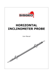
_ H-LEVEL
monitoring system
USER MANUAL
www.sisgeo.com
H-LEVEL_EN_00_14
Page 1 of 16
H-LEVEL
INDEX
www.sisgeo.com
IntroduCTION
Page 4
Description
Page 5
preliminary checks
Page 6
INSTALLAtion
Page 7
TAKING MEASUREMENTS
Page 13
DATA MANAGEMENT
Page 13
Troubleshooting
Page 14
MAINTENANCE
Page 15
APPENDIX
Page 16
H-LEVEL_EN_00_14
Page 2 of 16
H-LEVEL
Notes on the use of product
For safe and efficient use of the product, please read carefully the following
instructions before starting any operation.
Any use of the product other than the one described in this manual shall be considered the
user’s full responsibility.
The same applies for any unauthorized modifications.
In addition to the hereby listed standards, the user must comply with the provisions of the
current legislation regarding personal safety and health together with all other persons in the
workplace.
SISGEO is not responsible for any accident, breakdown or other problems due to lack of
knowledge and / or non-compliance with the requirements contained in this manual.
Check that the product has not been damaged during the transport.
Verify that the package includes all items as well as any requested optional accessories; if
anything is missing, please promptly contact SISGEO.
The user must strictly follow all the operations described in this manual.
Maintenance or repair of the device is permitted only by authorized operators.
These operators must be physically and intellectually suitable.
For information about instrument or to order spare parts, always specify the product
information which can be found on the identification label.
When replacing parts, always use ORIGINAL SPARE PARTS.
The manufacturer reserves the right to make either technical and / or commercial changes
without prior notice.
It is our policy to keep manuals continuously updated.
Symbols
Pay particular attention to the following instruction.
Identification
www.sisgeo.com
Instruments can be identified
• From a production lot number (written on the Compliance Certificate)
• From a serial number (s/n) engraved indelibly on the instrument
• From a label on the instrument
• From a label on the cable
H-LEVEL_EN_00_14
Page 3 of 16
H-LEVEL
INTRODUCTION
H-level settlement gauges are used to monitor subsidences and/or settlements in buildings
and structures.
An H-level system is composed by a reference tank, placed out of the area that has to be
monitored, and by one or more settlement gauge based on pressure transducer.
The settlement gauges are placed in the points of interest and are connected through two
flexible tubes.
One tube contains the liquid, the other is necessary for the barometric compensation,
which is common to all the settlement gauges .
During the plant design phase, we suggest to install a settlement gauge near the tank (in a
stable zone not subject to settlements) in order to have some measurements to compare
to the other settlement gauges.
The vertical movement of a settlement gauge modifies the level of the head between the
tank and the settlement gauge, creating a pressure variation.
It is possible, on request and for particular applications, to ask for the horizontal installation
of the settlement gauge.
www.sisgeo.com
H-LEVEL_EN_00_14
Page 4 of 16
H-LEVEL
DESCRIPTION
The H-LEVEL settlement gauge consists of:
2
4
6
1
1. Settlement gauge;
2. hydraulic tube connectors Ø 10/12
mm;
3. barometric compensation tube
connectors Ø 6/8 mm;
4. drain valve;
5. fixing plate;
6. plugs (hole Ø 12mm);
7. connector.
3
5
7
The tank consists in:
5
7
2
6
4
1
1. Measure tank (lower part);
2. autofilling tank (upper part);
3. hydraulic tube connector
Ø10/12mm;
4. water level control;
5. air filtering and drying system
on tubes for barometric
compensation;
6. plugs;
7. cap.
In the packaging there are also circuit
closure caps (to be installed in the last
settlement gauge of the circuit).
3
www.sisgeo.com
H-LEVEL_EN_00_14
Page 5 of 16
H-LEVEL
Usually the liquid used is a water-glycerine mix (50% water, 50% glycerine).
This mix has been chosen for its high temperature range without substantial changings in
physical features, to its low gas tension and for the lack of seaweeds and mould formation.
In addition, it is also chemically inert to the materials composing the system and
environmentally non-dangerous.
The medium density is 1.1555 g/cm3 .
The saturator is an optional accessory used to fill the circuit.
It consists in:
5
4
2
3
1. A stainless steel container of
Ø250mm and about 20l. capacity;
2. a valve for Ø 6/8 tube;
3. a valve for Ø 10/12 tube;
4. manometer;
5. compressor connection;
It is combined with a portable
compressor with rechargeable battery.
1
PRELIMINARY
CHECKS
www.sisgeo.com
Useful tools:
• Spanner n° 12 e 18
• Screwdriver
• Allen key n° 5,10
• Drill and tips of Ø 9 and 12mm suited for the material to be drilled
• Cutter
• Bucket
• Rags
• Funnels
• Raceways with plugs for fixing tubes and cable
H-LEVEL_EN_00_14
Page 6 of 16
H-LEVEL
INSTALLATION
Connectors wiring
The electrical cable to be connected to the instrument generally has already a connector on
one side.
On request, it is possible to supply a cable reel from which it is possible to cut the single
parts.
In this case, it is necessary to wire the connectors as follows:
PINS
FUNCTION
N° 1
+Loop
N° 2
Thermistor
N° 3
Thermistor
N° 4
- Loop
N° 5
Shield
Precautions and suggestions
Verify the correct functioning of every sensors before starting the installation.
The value you read without pressure is around 4mA.
If installed outside, provide a roofing in order to supply some repair from the bad weather
conditions.
The settlement gauges have to be installed at the same height and below the level of the
tank without exceeding the range of the settlement gauge.
Consider also the expected settlements.
~120mm
<Sensor
Full scale
If insulation is used, it is necessary to cover the whole circuit, also near the settlement
gauge. Use suitable insulation foams.
www.sisgeo.com
H-LEVEL_EN_00_14
Page 7 of 16
H-LEVEL
Settlement gauge installation
4
2
3
1
www.sisgeo.com
•
•
•
Fix the instrument with the supplied plugs (1). Hole Ø12 mm;
fit the 4 tubes on their connectors and screw the sleeves (2);
to help the drain, we suggest to fix the tubes (3) on the wall in order to keep them
below the connector (see picture below);
•
•
ensure that the drain valve is closed (4);
arrange a container to receive the liquid that drains from the last settlement gauge.
H-LEVEL_EN_00_14
Page 8 of 16
H-LEVEL
Tank installation
•
•
3
5
•
•
2
6
•
•
Fix the tank with the 4 plugs
supplied (1). (Hole Ø12mm);
connect the filter system (3) to
the tank using the 6/8 tube that
is ca. 20cm long (2) and fix it to
the wall higher than the tank.
(Hole Ø9mm);
close the valve (4);
remove the cap (5) and fill
in the tank using a funnel
and cheking the water level
control (6). (the volume is
approximately 7l.);
close the cap (5);
keep the valve closed (4).
1
4
7
Filling of the circuit
It’s possible to fill in the circuit in two ways:
• using gravity (for short circuits of 15/20m)
• using the saturator.
Note: Approximately, you need about 8 l. x 100 m.
Using gravity
•
•
•
•
•
•
•
•
www.sisgeo.com
Close the valve (7);
use a suitable container and connect it to the valve (7);
put the container at a level that allows to fill in the circuit. Do not exceed 10m. head;
open the valve (7);
drain the liquid from the last settlement gauge;
when the whole circuit is filled, and there are no air bubbles, close the connector with
the cap supplied (see next paragraph);
close the valve (7) and disconnect the container;
drain the settlement gauge as explained next.
H-LEVEL_EN_00_14
Page 9 of 16
H-LEVEL
Using the saturator
3
1
2
Open both valves (1-2).
Remove the plastic cap (3).
4
2
1
Fill the tank using a funnel (4) with the mix
necessary to fill the whole circuit.
It is important to fill the circuit in a single time.
Close the valves (1-2) and connect the
compressor.
Turn on the compressor (5) and reach a
pressure of about 4 bar.
Do not disconnect the compressor.
5
www.sisgeo.com
H-LEVEL_EN_00_14
Page 10 of 16
H-LEVEL
5
6
Open carefully the valve (2).
Do not exceed 1 bar of output
pressure (8).
Attention: a pressure too high
could irremediably damage
the settlement gauges.
2
7
Put the saturator with the valves
upside down.
Connect the saturator to the tank (6)
using the 10/12 tube (7).
8
Let the liquid drain from the last
settlement gauge (9) to eliminate any
air bubbles within the circuit.
9
Put the supplied cap on the last
settlement gauge (10) and close the
valve (2) of the saturator.
2
10
During the closure of the last
settlement gauge, close the tank
valve (11).
Disconnect the saturator from the
tank (6).
6
2
11
www.sisgeo.com
H-LEVEL_EN_00_14
Page 11 of 16
H-LEVEL
Open the tank valve (12) and let
the tank liquid touch the settlement
gauges.
Open for 2 second the valve (11) to
drain air.
Pay attention to the liquid spill.
12
11
13
Open the drain valve (13) for 2/3
second and close it immediately.
Repeat this operation for every
settlement gauge.
Read each settlement gauge and
verify that they are in the required
value.
If necessary, move them up or down.
Tank auto-filling
The tank has an auto-filling system, that allows the liquid level to remain stable also in case
of little leaks in the circuit.
This example shows how to notice the spills analyzing the data.
This behaviour will be registered on all settlement gauges and will be necessary to find and
fix the leak on the circuit.
www.sisgeo.com
H-LEVEL_EN_00_14
Page 12 of 16
H-LEVEL
TAKING
MEASUREMENTS
Manual readings are taken connecting the conductors to a readout according to the following
scheme:
Sensors with
4-20 mA signal
current loop
COLOUR
FUNCTION
PINS
Red
+Loop
1
Black
- Loop
4
White
Thermistor
2
Green
Thermistor
3
Shield
Shield
5
To obtain reliable measures we recommend a warm up time not less than 10 seconds.
DATA MANAGEMENT
The following formulas allow to convert the electric measurements into engineering values:
Linear factor
Polynomial factor
Leng = Lele/S [mm H2O]
Leng = (Lele2 x A) + (Lele x B) + C [mm H2O]
Leng = Engineering unit
Lele = Electric unit
S = linear sensitivity factor
A, B, C = polynomial conversion factors
S, A, B, C are stated on Calibration Report.
The excercise readings refer to the initial reading (zero reading).
∆mm
H2O
= Li - L0
L0 = Zero reading [mm H2O]
Li = Excercise reading [mm H2O]
Zero reading shall be taken carefully once the installation is performed and the instrument is
in operating conditions.
For many applications is necessary to wait several days to obtain a reliable zero reading. We
suggest to take the readings in a short lapse of time to verify if the system is stable.
Note: in case the liquid used is a mix of 50% water and glycerine, the obtained
values in mm must be divided for 1,1555.
Please consider what is written in the introduction paragraph on the way to connect data.
www.sisgeo.com
H-LEVEL_EN_00_14
Page 13 of 16
H-LEVEL
Temperature measure
With a Sisgeo readout, the temperature is taken directly in °C.
If you measure thermistore resistance value, you have to convert it using the formula or the
table in Appendix 1.
Data analysis note
Generally speaking, but especially when there are complex circuits, it is necessary to use a
statistical approach to analyze the data and cancel any temperature effect on the measures.
Problem
Overrange
measure
OmA
measure
Unstable measure
TROUBLESHOOTING
www.sisgeo.com
Possible cause
Solution
Shield not connected
Connect the shield
Electro-magnetic fields nearby
(engines, generators, radio antennas,
welders, high voltage lines...)
Identify and remove the cause.
Data acquisition system grounding not
Provide efficient grounding
well done.
Open circuit
Make a correct connection
Wrong connection
Make a correct connection
High absorption
Fix critical point
Short circuit
Fix critical point
H-LEVEL_EN_00_14
Page 14 of 16
H-LEVEL
MAINTENANCE
Check periodically the hygroscopic salts status in
the air filter system and change them when 50%
is shown.
Check for leaks in the tubes.
In case of cuts, we recommend to use joints connectors (see photo below)
MAINTENANCE
SERVICE
After-sales assistance for calibrations, maintenance and repairs, is performed by SISGEO’s
service department.
The authorization for shipment shall be activated by RMA “Return Manufacturer
Authorization”. Create your account and then fill in the RMA module clicking on:
http://www.sisgeo.com/repairs.html
Send back the instrument/equipment with the complete accessories, using suitable
packaging, or, even better, the original ones.
The shipping costs shall be covered by the sender.
Please return to the following address with correct delivery documentation:
SISGEO S.r.l.
Via F.Serpero, 4/F1
20060 MASATE (MI)
On the delivery document it is mandatory to indicate the RMA code received.
Technical assistance e-mail: [email protected]
www.sisgeo.com
H-LEVEL_EN_00_14
Page 15 of 16
H-LEVEL
APPENDIX 1
THERMISTOR TEMPERATURE CONVERSION
Resistance to temperature equation:
1
T=
=273.2
A + B ( LnR ) + C ( LnR )3
Where:
T= temperature in °C
LnR= natural Log of the thermistor resistance
A= 1.4051x10⁻³ (coefficents calculated over the -50 to +70°C span)
B= 2.369x10⁻⁴
C=1.019x10⁻⁷
www.sisgeo.com
Ohms
Temp
Ohms
Temp
Ohms
Temp
Ohms
Temp
16.60K
-10
5971
10
2417
30
1081
50
15.72K
-9
5692
11
2317
31
1040
51
14.90K
-8
5427
12
2221
32
1002
52
14.12K
-7
5177
13
2130
33
965.0
53
13.39K
-6
4939
14
2042
34
929.6
54
12.70K
-5
4714
15
1959
35
895.8
55
12.05K
-4
4500
16
1880
36
863.3
56
11.44K
-3
4297
17
1805
37
832.2
57
10.86K
-2
4105
18
1733
38
802.3
58
10.31K
-1
3922
19
1664
39
773.7
59
9796
0
3784
20
1598
40
746.3
60
9310
-1
3583
21
1535
41
719.9
61
8851
2
3426
22
1475
42
694.7
62
8417
3
3277
23
1418
43
670.4
63
8006
4
3135
24
1363
44
647.1
64
7618
5
3000
25
1310
45
624.7
65
7252
6
2872
26
1260
46
603.3
66
6905
7
2750
27
1212
47
582.6
67
6576
8
2633
28
1167
48
562.8
68
6265
9
2523
29
1123
49
543.7
69
525.4
70
H-LEVEL_EN_00_14
Page 16 of 16