1
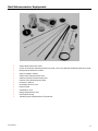
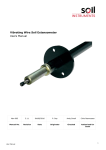
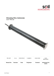
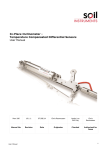
Rod Extensometer User Manual Man 012 1.1.1. 21/03/2013 C Spalton Andy Small Chris Rasmussen Manual No. Revision Date Originator Checked Authorised for Issue User Manual 1 Contents Section 1 : Introduction ................................................................................................................................. 3 Section 2 : General Information ................................................................................................................. 4 Section 3 : Installation Techniques ........................................................................................................... 5 3.01 3.02 Section 4 : 4.01 4.02 Downward Drillhole Installation ................................................................................................. 5 Upward Drillhole Installation....................................................................................................... 9 Reading Technique .................................................................................................................. 11 Digital Depth Gauge.................................................................................................................... 11 Dial Depth Gauge ........................................................................................................................ 11 Appendix A. Rod Extensometer Equipment .......................................................................................... 13 Appendix B. Rod Extensometer Installations ...................................................................................... 14 Appendix C. Rod Extensometer Record Sheet ..................................................................................... 15 User Manual 2 Section 1 : Introduction This instruction manual describes the techniques required for the installation and reading of the multiple rod extensometer with grouted anchors in drillholes at any orientation. Installation and reading of the single rod system is just a simpler version of the procedure described in the following text. It is essential that the equipment covered by this manual should be installed and operated by competent and suitably qualified personnel. The techniques described are intended to serve as a general guide and will vary to suit particular site conditions. User Manual 3 Section 2 : General Information With reference to Figs. 1 and 2, the single rod extensometer employs a rod, anchored at one end of a drillhole, passing into a reference tube fixed in the hole collar. Relative movement between the end anchor and the reference tube is measured with either a dial depth gauge, digital depth gauge or an electric transducer inserted through a reference head and registering on the free end of the rod. A range adjustment screw fitted to the end of the rod extends the reading range beyond that of the measuring instrument. Multiple rod installations monitor displacements at various depths using rods of different lengths. Several single rod units may be installed in close proximity in drillholes of small diameter. Alternatively, several rods may be installed side by side within a single larger hole to form the multiple rod type. Each rod is individually isolated by a close-fitting protective plastic sleeve. The complete assembly is grouted in place, fixing the anchors to the parent material but allowing free movement of each rod within its sleeve. A single reference head receives all rods from the one installation for the multiple rod type. Facilities are available for both digital and dial depth gauges or digital remote readout in addition to a visual alarm system to give warning of excessive movements and to indicate when readings are required. Rod extensometers can be surface mounted to measure displacements across tension cracks or joints and can be buried in fill or cast in concrete. The rod extensometer system is reliable, accurate and relatively simple to install and read. It is free from creep, kinking and other inaccuracies associated with the use of tensioned wire and can be coupled to a transducer readout for continuous or remote control. It can be installed in boreholes or drillholes at any orientation with the hole diameters of 38-101 mm depending on the number of rods. Operating lengths greater than 100 m are possible in favourable conditions. A reset range adjustment of up to 500 mm is provided. User Manual 4 Section 3 : Installation Techniques The installation procedures outlined in this text are intended as a general guide and flexibility in the interpretation of them is required to suit particular local site conditions. Only grouted multiple rod extensometers are discussed. Single rod installations are a simple version of the multiple rod and therefore the following procedures can be easily adapted when necessary. The technique used is dependent upon the orientation of the drillhole with respect to vertical and the consequent effect of gravity on grouting operations. For downward holes gravity assists grouting; for horizontal and upward holes the opposite is the case and sealing of the drillhole at the reference head the provision of grout return/air bleed pipes are necessary. 3.01 Downward Drillhole Installation The drillhole is bored to the required depth using conventional drilling techniques. The datum/tube plate is rigidly fixed to the drillhole entrance and the sleeve guide plate fitted to it. As an installation aid the sleeve support/clamp unit is temporarily fixed to the sleeve guide plate. One length of plastic protective sleeve is secured to an anchor unit. The assembly is inserted through the sleeve support/clamp unit and sleeve guide plate and further sleeves added by PVC-cemented flush couplings, with the sleeves being clamped as each joint is made, until the anchor reaches the required depth. The sleeve assembly is clamped in the sleeve support/clamp unit. A grout tremie pipe is inserted to the base of the drillhole, followed by the remaining anchors and sleeves. Grout is then pumped through the pipe, and the pipe withdrawn, so that the final grout level is within a short distance of the sleeve guide plate. The grout is left to set. The sleeve support/clamp plate is removed and the sleeves cut back flush with the sleeve guide plate. Lengths of extensometer rod are then inserted into the sleeves using metal adhesive to join each coupling - no adhesive is applied to the end of the first rod which receives the anchor. The rod assembly is temporarily supported when making each joint and the procedure repeated until the first rod locates in the anchor. The final rod is cut to size and threaded to accept the range adjustment unit, which is fitted and approximately set using the range adjusting tool. When the remaining rods have been installed the reference head is bolted in place and final range adjustments made on the adjustment units to obtain base readings using either digital or dial depth gauges or an electric transducer. a) Finalise with the Engineer the following: precise location and orientation of the proposed drillhole, number and depth of anchors (when possible each anchor should be located a whole number of metres beneath the datum plate), grout mix specification, if the reference head is to be recessed into the rock face. b) Specify drillhole diameter and depth: 75-101 mm and minimum 500 mm beyond the deepest anchor, respectively. c) Form drillhole as specified. d) If required, form recess concentrically at the drillhole entrance. The depth of recess is dictated by the degree of protection to be provided to the reference head of the completed extensometer and must be balanced against the access problems associated with increasing depth, which are particularly important during installation. The recess should be fitted with a removable protective cover. User Manual 5 The recess can be formed in one of two ways: (i) using a large diameter overcoring bit, typically 250 mm diameter, or (ii) drilling closely-spaced holes around a template of the appropriate diameter and chipping out the core to the required depth. The first method is the more convenient but under certain circumstances it may be necessary to employ the second. (i) Upon completion of the drillhole attach the appropriate overcoring bit and drill to required recess depth. Ensure no debris falls into the drillhole during core removal. Using a chisel if necessary ensure that the bottom of the recess is level. (ii) Temporarily seal the drillhole with a rubber packer or similar pushed to slightly below the required recess depth. Fit the template concentrically to the drillhole and drill closely spaced holes around its circumference to the recess depth. Remove the template and drill as many holes as possible in the central core. Using a chisel remove the core material and ensure that the bottom of the recess is level. Remove the rubber packer. (e) The datum/tube plate, and ultimately the complete reference head assembly, is rigidly fixed to the drillhole entrance by three ragbolts anchored into the parent material. To ensure correct orientation of the sleeve guide plate with respect to the numbered reference bushes in the reference head, the ragbolts are not equally spaced on their common diameter on the datum plate but form an isosceles triangle. The orientation of this triangle and the individual reference bushes with respect to sight lines during instrument reading with the digital or dial depth gauge are important in conditions of restricted access. Ensure that the surface at the drillhole entrance has been trimmed as flat as possible over the area of the datum plate and is perpendicular to the drillhole axis. Having made due allowance for the points discussed above, drill three ragbolt holes, minimum diameter 30 mm, minimum depth 200 mm, parallel to drillhole axis. In soft rock it may be necessary to form a cement grout pad at the drillhole entrance to prevent rock breaking away between the ragbolt holes and the drillhole. Blow out ragbolt holes with compressed air. Offer the datum/tube plate with ragbolts attached to the ragbolt holes. Check that the datum plate beds onto the trimmed surface and that the datum/tube plate and drillhole are concentric. Remove the datum/tube plate with ragbolts attached. The resin cement kit comprises a three pack polyester-based resin compound with a setting time of approximately 30 minutes at 20°C. Full instructions are supplied. Mix sufficient quantity of resin cement. Fill the ragbolt holes and coat the back of the datum plate (to fill any irregularities in the trimmed rock surface). Immediately fit the datum/tube plate with ragbolts attached into position. Ensure that the datum/tube plate and drillhole are concentric and that the datum plate is perpendicular to the drillhole axis. Hold firmly in place until the resin cement has set. f) Undo the nuts and remove the washers from the ragbolts and fit the sleeve guide plate onto the datum plate so that the surface on which the hole identification numbers are embossed is uppermost. Replace the washers and nuts, and tighten. g) Fit the sleeve support/clamp unit to the sleeve guide plate. Locate the two bolts and associated mounting pillars in the corresponding threaded holes in the sleeve guide plate, and tighten. h) Collect sufficient lengths of protective sleeve for the total installed length of extensometer rods. Separate into groups corresponding to the required length of each completed rod assembly. Collect required number of anchor units. Install the deepest anchor and sleeve as follows. Ensure that the sleeve adaptor supplied with the anchor unit is tightly threaded onto the anchor. Clean both the female end of the User Manual 6 first length of sleeve and the sleeve adaptor with PVC cleaner. Apply PVC cement to the (male) sleeve adaptor and flush couple the sleeve to the adaptor. Remove any excess PVC cement. Insert the assembly through the appropriately numbered hole (i.e '1') in the sleeve guide plate and carefully lower until the top of the sleeve is at a convenient height for making the next flush coupling. Tighten the respective clamping screw on the sleeve support/clamp unit to hold the sleeve. Take the next length of sleeve and clean both the male end of the first length and the female of the next with PVC cleaner. Apply PVC cement to the male end of the first length and flush couple. Remove any excess PVC cement. Allow sufficient time for the PVC cement to set (1-5 minutes depending on temperature). Test the coupling by slowly applying tension by hand to ensure that it is sufficiently strong to support the weight of sleeve and anchor below it. Hold the sleeve, release the clamping screw and carefully lower until the top of the sleeve is at a convenient height for making the next flush coupling. Repeat the procedure until the anchor is installed to the required depth; tighten the clamping screw to hold in position until grouting is complete. Leave any excess sleeve length protruding. (The sleeves may sometimes be greased to reduce adhesion with the grout). i) Install the tremie pipe to the drillhole bottom by lowering through the centre hole in the sleeve support/clamp unit and sleeve guide plate. Cut to length to suit future location of the grout pump. j) Repeat (h) to install all remaining anchors and protective sleeves, starting from the deepest and progressing to the shallowest. k) Pump grout through the tremie pipe to within approximately 500 mm of the sleeve guide plate. Remove the tremie pipe and top up the grout level as necessary. Flush the tremie pipe with water. Allow grout to set. l) Remove the sleeve support/clamp unit from the sleeve guide plate by unscrewing the two locating bolts and lifting over the protruding protective sleeves. m) Cut back each protective sleeve flush with the sleeve guide plate. n) Collect sufficient lengths of extensometer rod and rod couplings for the total installed length. Separate into groups corresponding to the required length of each completed rod assembly. Fit one rod coupling to each individual length of extensometer rod: apply metal adhesive to one end of the coupling and screw tightly into one threaded end of the corresponding rod. Each rod will now have one female end and one male end. Install the deepest rod as follows. Take the first length of rod and insert the female end through the appropriately numbered hole (i.e '1') in the sleeve guide plate. (Do not apply any metal adhesive to the female end of the first rod). Insert a pin through the tommy bar hole in the coupling and carefully lower the rod to a convenient height for making the first joint. Clamp mole-grips tightly to the first rod and apply metal adhesive to the exposed male end of the previously fitted coupling. Screw the second rod tightly onto the first rod. Remove the pin from the hole in the first coupling and insert through the hole in the second coupling. Unclamp the mole-grips and carefully lower the rod assembly to a convenient height for making the next joint. Clamp mole-grips tightly to the rod assembly. Repeat the procedure until the full length of rod has been installed. Rotate the rod assembly to join it to the anchor. Mark sleeve guide plate level on the rod assembly. Repeat for all remaining rod assemblies, starting from the deepest anchor and progressing to the shallowest. o) The precise and final lengths of the completed rod assemblies are dependent on the anticipated direction and magnitude of movement, and the type of range adjustment User Manual 7 units fitted. With accurate pre-planning of the anchor locations with respect to the reference head it is possible to keep any necessary cutting of the rods to a minimum. Collect sufficient range adjustment units. Rotate one rod assembly to unscrew the rod from the anchor, withdraw from the protective sleeve to a convenient height and clamp tightly with mole-grips. With due consideration given to the factors discussed above, use a hacksaw to cut the rod to length using the marked sleeve guide plate level as a reference. The cut must be square; use a file to square the edges if necessary. Use the thread tap and wrench supplied to form a thread into the rod end, minimum depth 20 mm. Take one range adjustment unit and tighten the plastic grub screw set in the brass collar sufficiently to hold the range adjustment screw in position. Unscrew the adjustment screw from the brass collar using the range adjustment tool supplied. Apply metal adhesive to the male thread on the brass collar and screw tightly into the tapped rod using the rod locating tool supplied. Unclamp the mole-grips, carefully lower the rod assembly down the sleeve and screw tightly onto the anchor using the rod locating tool. Fit the adjustment screw into the brass collar and set to approximate correct height using the range adjustment tool. Repeat for all remaining rod assemblies. p) Undo the nuts and remove the washers from the ragbolts. Fit the reference head onto the sleeve guide plate. Replace the washers and nuts, and tighten. q) Normally, the reference bushes are fitted to the reference head during manufacture. A step is cut into each bush to provide a key for the dial depth gauge. In certain circumstances, for example in conditions of restricted access during reading of an instrument or when the number of rod assemblies (and therefore bushes) differs from one instrument to the next, it may be necessary to fit the bushes on site. A bush mandrel is provided for this purpose. Fit the bush into the respective numbered hole in the reference head, fit the mandrel into the bush and hammer until the bush is inserted to full depth in the reference head. Repeat for all other holes corresponding to installed rod assemblies. In conditions of restricted access, the step in each bush should be orientated such that the digital or dial depth gauge will be at a convenient angle to the observer during reading of the instrument. r) Fit the digital or dial depth gauge to one reference bush. Note the reading and compare with the base reading required, which is dependent on such factors as the magnitude and direction of expected movement. Remove the depth gauge. Insert the range adjustment tool through the bush to set the range adjustment unit to the correct height. Refit the depth gauge, note the reading, compare with the base reading required and continue the above procedure until the range adjustment unit is correctly set. Repeat for all remaining rod assemblies. s) With reference to (d), fit protective cover if required. User Manual 8 3.02 Upward Drillhole Installation The drillhole is bored to the required depth using conventional drilling techniques. The datum/tube plate is rigidly fixed and sealed with resin cement to the drillhole entrance and the sleeve guide plate fitted to it. As an installation aid the sleeve support/clamp unit is temporarily fixed to the sleeve guide plate. One rod position in the sleeve guide plate is used for the grout return/air bleed pipe, the first length of which is inserted through the sleeve support/clamp unit and sleeve guide plate. Further lengths of grout return/air bleed pipe are added by PVC-cemented flush couplings until the end of the drillhole is reached; the pipe is then withdrawn a short distance and clamped in the sleeve support/clamp unit. One length of plastic protective sleeve is secured to an anchor unit and the assembly inserted through the sleeve support/clamp unit and sleeve guide plate. Further sleeves are added by PVC-cemented flush couplings until the anchor reaches the required depth. The sleeve assembly is clamped in the sleeve support/clamp unit and the procedure repeated until all remaining anchors and sleeves are installed. The primary grout stem is screwed into the central hole in the sleeve guide plate. The sleeve guide plate together with the sleeve support/clamp unit, installed sleeves, anchors, grout return/air bleed pipe and primary grout stem are separated from the datum plate and with the entire assembly supported, resin cement is packed around the sleeves and primary grout stem to form an effective grout seal on the back face of the sleeve guide plate. The assembly is then bolted back onto the datum plate and the resin cement left to set. A small quantity of grout is pumped through the primary grout stem and allowed to set to form a grout plug immediately behind the sleeve guide plate. Grout is then pumped through the primary grout stem until grout flows from the grout return/air bleed pipe. The primary grout stem is sealed and the grout left to set. The sleeve support/clamp plate is removed and the sleeves cut back flush with the sleeve guide plate. Lengths of extensometer rod are inserted into the sleeves using metal adhesive to join each coupling - no adhesive is applied to the end of the first rod which receives the anchor. The rod assembly is temporarily supported when making each joint and the procedure repeated until the first rod locates in the anchor. The final rod is cut to size and threaded to accept the range adjustment unit which is fitted and approximately set using the range adjusting tool. After the remaining rods have been installed the reference head is bolted in place and final range adjustments made on the adjustment units to obtain base readings with either a dial depth gauge or an electric transducer. a) As described in 2.1 a). b) Specify drillhole diameter: 75-101 mm. Specify drill hole depth: absolute minimum 500 mm beyond the deepest anchor. The depth is dependent upon the location of the deepest anchor and the effect of the angle of inclination on the area of the horizontal surface formed by the (liquid) grout, such that the anchor is fully grouted to the parent rock. The nearer a drillhole is to the horizontal the more pronounced this effect becomes and the greater must be the distance between the deepest anchor and the end of the drillhole. c) Form drillhole as specified. d) As described in 2.1 d) - g). e) Collect sufficient lengths of grout return/air bleed pipe (which is identical to the protective sleeves) for the total drillhole depth. Insert the female end of the first length through the appropriate numbered hole in the sleeve support/clamp unit and sleeve guide plate (i.e. highest number) and push up to a User Manual 9 convenient position for making the flush coupling. Tighten the respective clamping screw on the sleeve support/clamp unit. Take the next length and clean both the male end of the first length and the female end of the next with PVC cleaner. Apply PVC cement to the male end of the first length and flush couple the two. Remove any excess PVC cement. Release the clamping screw and push the grout return/air bleed pipe up to a convenient position for making the next flush coupling. Repeat the procedure until the end of the drillhole is reached. Withdraw the grout return/air bleed pipe 50 mm and retighten the clamping screw. f) As described in 2.1 h) and j). g) Screw the primary grout stem into the threaded central hole in the sleeve guide plate and tighten. h) Undo the nuts and remove the washers from the ragbolts. Separate the sleeve guide plate, with the sleeves and anchors etc. attached, from the datum plate and temporarily support. Mix sufficient quantity of resin cement and pack liberally on the back face of the sleeve guide plate, particularly around the sleeves and the primary grout stem. Refit the sleeve guide plate on the datum plate, replace the washers and nuts, and tighten. Allow sufficient time for the resin cement to set. i) Connect the grout pump pipe to the pipe adaptor on the primary grout stem. Pump sufficient grout to just cover the primary grout stem, disconnect the grout pump pipe and allow any excess grout to drain. Ensure that the primary grout stem bore is clear. Allow grout to set. j) Reconnect the grout pump pipe to the pipe adaptor on the primary grout stem. Pump grout. Continue until grout of identical consistency to that entering the drillhole exits the grout return/air bleed pipe. Disconnect the grout pump and seal the primary grout stem. Allow grout to set. k) As described in 2.1 l) - s). Note The procedure outlined above is based on the assumption that the parent rock into which the drillhole is formed is sufficiently competent to withstand the grouting pressures without any appreciable grout loss. When the rock is fissured it may be necessary to conduct a water pressure test on the drillhole to the same pressures as expected during grouting. If indicated by the results of the test the drillhole will have to be pre-grouted over the fissured length and rebored. Grouting will then be possible as described above. User Manual 10 Section 4 : Reading Technique While not essential it is recommended that after base readings have been taken on a particular reference head, the same digital or dial depth gauge is used for all subsequent readings. Both digital and dial depth gauge plungers are fitted with a flat anvil to locate on the hemispherical end of the range adjustment units. A calibration tube set to precisely 10 mm is supplied. 4.01 Digital Depth Gauge The digital depth gauge comprises a digital readout display and three function buttons. "ON" Switches Indicator on and will also reset the Display to Zero at any point throughout the spindle travel. "PRINT" Sends the displayed reading to a Printer or Computer. "MODE" This button has two separate functions. (1) (2) INCH to METRIC conversion of the displayed reading is achieved by keeping the button depressed for over 2 seconds. Releasing the button will cause the Display to change to the conversion of that previously displayed. A short press and release (less than 2 seconds) will hold the displayed reading regardless of spindle movement. Another similar depression will release the "hold" and return the Indicator to normal operating conditions. feature Technique for reading with digital depth gauge is as follows: (a) Carefully remove gauge and calibration tube from the carrying case. Press the "ON" button. Check that the plunger is fully extended and the Display is showing Zero. Ensure that correct measuring system is displayed and change if necessary using "MODE" button. Gently insert the depth gauge into the calibration tube to full depth with the boss located in the step cut into the tube. Hold tightly in place. Check that the reading indicated 10.00 mm. Gently remove the gauge from the tube and replace the tube in the case. (b) Gently insert the gauge into the first reference bush to full depth with the boss located in the step cut into the bush. Hold firmly and note reading. If reading is not visible press the "MODE" button to "hold" the reading, or alternatively zero the reading using the "ON" button. Gently remove the gauge and note reading. Compare with base reading to determine magnitude and direction of movement. Repeat for all reference bushes. 4.02 Dial Depth Gauge (a) The dial depth gauge comprises a 75 mm diameter gauge with a rotating adjustable scale and a stainless steel boss to ensure constant orientation in the reference bushes. The dial gauge plunger is fitted with a flat anvil to locate on the hemispherical end of the range adjustment units. A calibration tube set to precisely 10 mm is supplied. Technique for reading with dial depth gauge is as follows:- User Manual 11 Carefully remove gauge and calibration tube from the carrying case. Gently insert the dial gauge into the calibration tube to full depth with the boss located in the step cut into the tube. Hold tightly in place. Check that the reading indicates 10.00 m. If not release the scale locking screw, rotate the scale to set 10.00 mm on the depth gauge and retighten the locking screw. Gently remove the dial gauge from the tube and replace the tube in the case. b) Gently insert the depth gauge into a reference bush to full depth with the boss located in the step cut into the bush. Note reading. Compare with base reading to determine magnitude and direction of rod movement. Gently remove the depth gauge from the bush. Repeat for all other rod assemblies. Note (i) In conditions of restricted access it may not be possible to view the depth gauge directly. With the depth gauge inserted into the reference bush the reading may be "frozen" by holding the centre of the gauge tightly between thumb and forefinger to prevent the needle rotating until after the dial gauge has been removed from the bush. (ii) The depth gauge is a sensitive instrument and should be treated with care. User Manual 12 Rod Extensometer Equipment Single Rod Reference Head Cover for Remote Reading Reference Head, Cover for Manual Reading Reference Head Multiple Rod Reference Head Sleeve Support Clamp Glass Fibre Extensometer Rod Stainless Steel Extensometer Rod Carbon Fibre Extensometer Rod Protective Sleeve Groutable Anchor Unit Datum Plate Installation Tool Range Adjustment Tool Dial Depth Gauge Vibrating Wire Displacement Transducer User Manual 13 Appendix A. Rod Extensometer Installations User Manual 14 Appendix B. Rod Extensometer Record Sheet Anchor/Rod Identification: Installation Details: Base Data: Reading: (mm) Date: Operator: Date Operator Serial No. Gauge Serial Number: Reading (mm) Movement (mm) Date Operator Serial No. Reading (mm) Movement (mm) Bell Lane, Uckfield, East Sussex t: +44 (0) 1825 765044 e: [email protected] TN22 1QL United Kingdom f: +44 (0) 1825 744398 w: www.itmsoil.com Soil Instruments Ltd. Registered in England. Number: 07960087. Registered Office: 5th Floor, 24 Old Bond Street, London, W1S 4AW User Manual 15