1
SECTION ONE
INTRODUCTION
• COMPONENTS
• Clock and Program Models Only
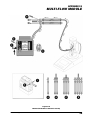
• See Figures 1.1 (GilAir-3) and 1.2 (GilAir-5)
(7) Liquid Crystal display (LCD)
• All Models
Note: All times are displayed in minutes.
(1) On/Off switch
(7.1) Battery icon. A flashing icon indicates
battery voltage is below its nominal value.
(2) Flow Adjustment (requires slotted
screwdriver)
(3) Rechargeable Battery Pack
(4) Internal/External Vent Control
Use a flat-head screwdriver to adjust the internal/
external vent. The open circle position will vent
the pump discharge external to the sampler case
(recommended for moist or corrosive sampling
environments). The closed circle will vent
internally (recommended for dust laden
environments).
(5) Battery Charge Indicator. Lights up when the
pump is turned on and the battery pack is fully
charged. The indicator will normally turn off after
the pump runs for a short period of time.
(7.2) Hold icon. Appears on Clock and Program
models when the MODE/HOLD is pushed
while the pump is running.
(7.3) D and R.
D = Delay interval prior to starting first
sampling interval (Program model only)
R = Run time interval (Clock & Program
models)
D + R = Pause interval between Run Time
Intervals (Program model only)
(7.4) Clock icon. Non-flashing: pump is
executing a sampling run. Flashing: pump
is in programming mode (Program model
only)
(6) Flow Fault Indicator. Lights up if pump is unable
to maintain flow rate within ± 5% of the set point.
Occurs if pump is operated outside its specified
performance ranges, or if battery pack has
insufficient charge.
After about 30 seconds of continuous operation
under fault conditions, the pump will stop.
For Clock and Program models, shutdown under
fault conditions preserves the run time in the
display.
REF 360-0040-01 (C)
9