1
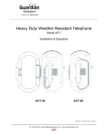
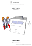
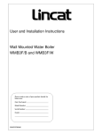
Industrial Communications Worldwide Prison Visitation System Model JP67 Installation and Operation P006219 Rev. D 111216 7/25/2014 12:12 PM 7552 - 10th Street N.E. Calgary, Alberta, Canada T2E 8W1 Ph: 403.258.3100 \ email:[email protected] \ www.guardiantelecom.com Guardian Telecom Inc. Installation and Operation Model JP67 Prison Visitation System Table of Contents Product Description ...............................................................................3 Distribution Node/Hub ...........................................................................3 Installing the Distribution Node..............................................................4 Installing the Desk Sets .........................................................................6 Wiring the System .................................................................................7 Product Specifications ...........................................................................8 Replacement Parts ................................................................................8 Warranty ................................................................................................9 Disclaimer..............................................................................................9 Warning .................................................................................................9 Service Telephone Number...................................................................9 Feedback...............................................................................................9 Guardian Product Return ....................................................................10 Table of Figures Figure 1 - System Block Diagram..........................................................3 Figure 2 - Distribution Node Dimensions...............................................4 Figure 3 - Distribution Node Isometric View ..........................................4 Figure 4 - Lawyer’s Side Phone ............................................................5 Figure 5 - Prisoner’s Side Phone ..........................................................5 Figure 6 - Prisoner’s Phone Mounting Holes.........................................6 Figure 7 - Wiring ....................................................................................7 Page 2 Guardian Telecom Inc. Installation and Operation Model JP67 Prison Visitation System Product Description The JP67 telephone system is a lawyer-prisoner communications arrangement that consists of a desk phone on each side of the security desk. The phone can be permanently attached to a desk surface with no surface gap or it can be desk top configured using the supplied rubber feet. A distribution node (hub) provides the communications link. The hub can be mounted in a discrete location (ceiling, floor, etc). The phone stations can be grouped with up to three sets per distribution node. The desk phones do not contain a ringer. Operations are simple, visiting lawyers and prisoners pick up their handsets to communicate. A non-mechanical hook switch is included within the stations to disconnect calls for added privacy. For connection the phones have both a two wire terminal and an RJ-11 connector for use as the installer prefers. Refer to manual P007459 “Theory of Equipment Operation” for an understanding as to how the system works. Distribution Node/Hub The distribution unit is a metal housing containing a power supply suitable for driving up to six phone units in isolated pairs. A circuit board containing the audio matching and power distribution is installed within the housing. A glanded hole for power entry and one for each of the desk set cables are provided. Figure 1 - System Block Diagram Page 3 Guardian Telecom Inc. Installation and Operation Model JP67 Prison Visitation System Installing the Distribution Node Follow all appropriate electrical codes and use only approved electrical fittings for the installation. Ensure mounting can support 2.2 lbs (1kg) and any additional load to which the Distribution Node may be subjected. Ensure that none of the electrical connection circuits are live. Remove the four (4) cover screws from the front of the unit and remove the front cover. Use the enclosure or the template to locate and drill four holes for #8 or M4 mounting screws. Start the two screws that will secure the top of the enclosure into the previously drilled holes. Slip the enclosure over the keyhole slots and secure at the two remaining screw holes. Tighten all four mounting screws. After wiring the system and checking for operation replace the cover. Figure 2 - Distribution Node Dimensions See: Figure 2 Distribution Node Dimensions. See: Wiring the System Figure 3 - Distribution Node Isometric View Page 4 Guardian Telecom Inc. Installation and Operation Model JP67 Prison Visitation System BACK VIEW SIDE VIEW 3.3" [84mm] 7.8" [199mm] 1.9" [48mm] 9.3" [237mm] Figure 4 - Lawyer’s Side Phone SIDE VIEW BACK VIEW 3.3" [84mm] 7.8" [199mm] 2.0" [51mm] 6.5" [165mm] 1/4-20 UNC 4 PLCS. 9.8" [250mm] 5.8" [146mm] Figure 5 - Prisoner’s Side Phone Page 5 Guardian Telecom Inc. Installation and Operation Model JP67 Prison Visitation System Installing the Desk Sets If the desk set is to be installed on the lawyer’s side simply set it in the desired location. Install the desk set on the prisoner’s side. o Using the template provided drill 5/16” diameter holes for bolts and cut out See: Figure 5 Prisoner’s Side Phone the square wiring hole through the desk top. o Refer to the section on wiring and connect wiring from the desk sets to the See: Figure 7 - Wiring node. o Secure the desk sets to the desk top with four ¼”-20 UNC x 2.5” tamper proof screws provided. 1.6" [41mm] 1.5" [39mm] 2.6" [66mm] 3.3" [84mm] 1.3" [32mm] 5.8" [146mm] PRISONER SIDE TELEPHONE HOLES TEMPLATE Ø0.3" [Ø6m 6.5" [165mm] Figure 6 - Prisoner’s Phone Mounting Holes Page 6 Guardian Telecom Inc. Installation and Operation Model JP67 Prison Visitation System Wiring the System Ensure that the power source is not live and connect 120 VAC wiring to terminal J1 on the hub PCBA. Insert the cable through the gland in the bottom of the enclosure and connect green to “GND”, white to “ACN” and black to “ACL” Wire the phones to the node. Connections at the phones can be to the terminal strip or to the RJ-11 connector. At the node install the phone loop two conductor cables through the supplied rubber grommet holes on the sides of the enclosure. Use the two left side lower holes for loop 1, the upper holes on each side for loop 2 and the two right side lower holes for loop 3. Connect loop 1 wire pairs to J2 / J3, loop 2 to J4 / J5 and loop 3 to J6 / J7. Note: the polarity is not important on the loop wire pairs. Apply power to the node and ensure that the red POWER ON indicator illuminates. Test each loop by lifting the handsets out of the cradles and observing that the red LEDs between the connections on the PCBA illuminate. Ensure that communication is possible between the two phones by talking over them. BACK VIEW PRISONER SIDE (STATION #1) DTR DISTRIBUTION NODE RJ-11 CONNECTOR STATION #2 STATION #1 TERMINAL BLOCK BACK VIEW ATTORNEY SIDE (STATION #1) RJ-11 CONNECTOR TERMINAL BLOCK Figure 7 - Wiring Page 7 STATION #3 See: Figure 7 - Wiring Warning: The power supply fuse in the hub is not replaceable, if it blows the power supply or the entire PCBA must be replaced. Guardian Telecom Inc. Installation and Operation Model JP67 Prison Visitation System Product Specifications ELECTRICAL REQUIREMENTS LINE VOLTAGE NOMINAL 120 VAC; 85-265 VAC 50/60HZ CONNECTION METHOD SCREW TERMINAL ENVIRONMENTAL TEMPERATURE -20O TO +60O C (7O TO +140O F) HUMIDITY 0 TO 80% RH MECHANICAL (HUB) BODY AND FACEPLATE CONSTRUCTION 16 GAUGE CRS, ZINC DICHROMATE PLATED AND POWDER COATED 11 X 5 X 2 INCHES (279 X 127 X 51 MM) DIMENSIONS H X W X D NET WEIGHT 2.2 LBS (1 KG) MOUNTING VERTICAL WALL OR CEILING WIRING ACCESS FOR POWER ONE ½“ OPENING WIRING ACCESS FOR TELEPHONE CABLES THREE ¼ “ OPENINGS ON EACH SIDE WITH PUSH THROUGH GROMMETS. STAINLESS STEEL HARDWARE MATERIAL MECHANICAL (LAWYER’S PHONE) BODY CONSTRUCTION ABS FILLED WITH POTTING COMPOUND HANDSET CONSTRUCTION HIGH IMPACT ABS DIMENSIONS H X W X D 9.3 X 7.8 X 3.3 INCHES (237 X 199 X 84 MM) NET WEIGHT 5.2 LBS. (2.4 KG) WIRING CONNECTION RJ11 CONNECTOR OR TERMINAL STRIP MECHANICAL (PRISONER’S PHONE) BODY CONSTRUCTION ABS FILLED WITH POTTING COMPOUND HANDSET CONSTRUCTION HIGH IMPACT ABS DIMENSIONS H X W X D 9.8 X 7.8 X 3.3 INCHES (250 X 199 X 84 MM) NET WEIGHT 5.4 LBS. (2.5 KG) WIRING CONNECTION RJ11 CONNECTOR OR TERMINAL STRIP REGULATORY (NODE ONLY) CSA/US CERTIFICATE: 2462147 CLASS: 4812-88 SIGNAL APPLIANCES Replacement Parts Part No. P007412 P007417 P007419 P007427 P005837 Description PCBA-Phone Hub - 3 Loop Power Supply-Hub (Note: Soldering Required) PCBA-Telephone Handset Assembly C/W 30” Armored Cord Proximity Reed Switch Page 8 Guardian Telecom Inc. Installation and Operation Model JP67 Prison Visitation System Warranty Guardian Telecom warrants your product to be free of defects in material and workmanship for a period of one year. Guardian Telecom will repair or replace any defective unit that is under warranty free of charge. This warranty is null and void if any non-authorized modifications have been made to this product, or if it has been subjected to misuse, neglect, or accident. This warranty covers bench repairs only; such repairs must be made at Guardian Telecom or an authorized service depot. Guardian Telecom is not responsible for costs incurred for on-site service calls, freight, or brokerage. A return authorization must be obtained prior to warranty claims or repairs. Disclaimer The products covered by this manual are designed for use in Industrial Environments and/or Hazardous Locations. Due to the range of possible applications for these instruments the manufacturer will not be responsible for damages or losses of any kind suffered as a result of the use of this product, including consequential damages. Warning For the purposes of installing the product and replacing fuses only, this device may be opened and reassembled by qualified personnel, following the instructions in the product manual. Service Telephone Number 1-800-363-8010 Guardian Telecom provides a customer service telephone number which is toll-free within North America. If you need assistance when installing or operating this product, please call the toll-free telephone number between regular business hours (8:00AM-5:00PM), Mountain Standard Time. If you are calling outside of regular business hours, please leave a detailed message, and a member of Guardian Telecom’s Service Department will return your call as soon as possible. If your product requires service, Guardian personnel will supply you with an RMA (return materials authorization) number over the telephone or through our web site product return page. This number must be included with your return address and the name of the person to contact. Guardian Telecom Inc. 7552 - 10th Street N.E. Calgary, Alberta, Canada T2E 8W1 Toll-free 1-800-363-8010 Ph. (403) 258-3100 Fax. (403) 253-4967 www.guardiantelecom.com Feedback Guardian Telecom continually strives to make reliable, durable, and easy to use products. If you, as an installer or user of our equipment, have any suggestions for improvements to this or any of our products or documents, including this manual, we would appreciate hearing from you. Page 9 Guardian Telecom Inc. Installation and Operation Model JP67 Prison Visitation System Guardian Product Return Guardian products have been quality tested and are in full working order when shipped from the factory, given the rugged nature of these products shipping is not expected to damage a unit. In the unlikely event of a malfunction, Guardian follows the three step procedure below. Step I - On-Site Correction The most common source of difficulties with a new product is improper installation in one of two ways: incorrect wiring connections or connection to an incorrect power source. Product wiring needs to be properly connected to the on-site wiring. Correct wiring instructions are shown in the user manual included with the product. Connecting a telephone to a standard power source, rather than tip & ring, will blow the telephone’s internal, user-replaceable fuse. In the event of fuse burn-out, disconnect the telephone from the power source, replace the fuse, and reconnect following the wiring diagrams provided with the product. Step II - Return Materials Authorization (RMA) When a product has been installed following user manual instructions, and the unit fails to operate, the user must contact Guardian Telecom to obtain authorization to return the product. This can be done by completing a RMA form online at www.guardiantelecom.com, or by calling the service telephone number given in this manual. After providing information on the product, the owner and the nature of the problem, Guardian will issue a RMA number, to be shown on documentation returned with the product. In addition to the RMA number, shipping documents should include name, address and telephone number of the owner along with contact information for the person responsible for the repair and/or the user who identified the malfunction. (Where a product is being returned for repair from outside of Canada, customs documentation must show the product’s serial number, date of export [date of purchase], and a notation that the equipment is: “Canadian goods returning.”) Step III - Factory Authorized Service Once received, each product is carefully inspected and tested. If the product is under warranty, repairs are completed and the product returned to the owner, generally within five working days of receipt by the factory. A product that has been subjected to misuse, neglect or accident or is beyond the warranty period will be evaluated. The service department will provide the owner’s representative with a repair cost estimate. Once approved, repairs are completed and the product returned, generally within five working days. Page 10 Guardian Telecom Inc. Installation and Operation Model JP67 Prison Visitation System Notes: Model No. Part No. Serial No. Date of Purchase Page 11 Guardian Telecom Inc. 7552 - 10th Street N.E. Calgary, Alberta, Canada T2E 8W1 Toll-free 1-800-363-8010 Phone (403) 258-3100 Fax. (403) 253-4967 www.guardiantelecom.com E-mail: [email protected] (Click to open message box) Industrial Communications Worldwide © Guardian Telecom Inc. 2011