1
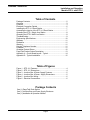
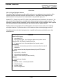
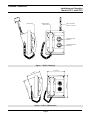
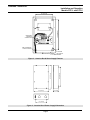
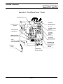
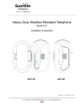
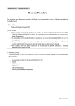
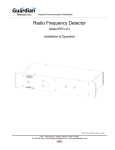
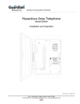
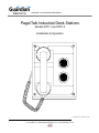
Industrial Communications Worldwide
Page/Talk Industrial Desk Stations
Models DTP-1 and DTP-5
Installation & Operation
V
O L U M E
3
4
C
L
5
1
2
H
A N N
E
P004915 Rev. G 12/6/2005 11:57 AM
7552 - 10th Street N.E. Calgary, Alberta, Canada T2E 8W1
Ph: 403.258.3100 \ email:[email protected] \ www.guardiantelecom.com
Guardian Telecom Inc.
Installation and Operation
Models DTP-1 and DTP-5
Table of Contents
Package Contents .................................................................................2
Overview ...............................................................................................3
Features ................................................................................................3
Electrical Connection Details.................................................................6
Installing the DTP-1/-5 Desk Station .....................................................7
Accessing the Interior of the DTP-1/-5 Desk Station .............................7
Operating the DTP-1 Single Line Station ..............................................8
Operating the DTP-5 Multi Line Station.................................................8
Troubleshooting.....................................................................................9
Engineering Specifications ..................................................................10
Warranty ..............................................................................................11
Disclaimer............................................................................................11
Warning ...............................................................................................11
Service Telephone Number.................................................................11
Feedback.............................................................................................11
Guardian Product Return ....................................................................12
Page/Talk Product Series Description.................................................13
Appendix A – Circuit Board Layout - Typical .......................................14
Appendix B – Typical Installation ........................................................15
Table of Figures
Figure 1 - DTP-1/-5 Features ................................................................4
Figure 2 - DTP-1/-5 Dimensions............................................................4
Figure 3 - Junction Box & Power Supply Features................................5
Figure 4 - Junction Box & Power Supply Dimensions ..........................5
Figure 5 - Junction Box Wiring ..............................................................6
Figure 6 - Electrical Connections...........................................................6
Package Contents
One (1) Page/Talk Desk Station
One (1) Junction Box and Power Supply Enclosure
One (1) Installation & Operation Manual
Page 2
Guardian Telecom Inc.
Installation and Operation
Models DTP-1 and DTP-5
Overview
DTP-1/-5 Page/Talk Desk Stations
Guardian's Page/Talk Systems provide reliable and easy to use paging and communication within
industrial environments such as plants, mills and factories. Individuals can be paged from any
station and two or more persons can communicate on any available party line.
Models DTP-1 (Single Line) and DTP-5 (Multi Line) desk stations are described in this manual. The
sets consist of two components; a desktop station and a junction box/power supply enclosure. The
enclosure houses the wiring board and a power converter board. A single customized cable supplied
with the set provides the connection between the enclosure and the desktop station.
Desktop stations are equipped with a 5 Watt speaker with volume control, and a noise reducing
microphone handset. A press bar switch on the handset enables one-hand paging operations.
Guardian's stations and related equipment are compatible with systems provided by most other
manufacturers.
Features
Desk Set Enclosure
• cover black PVC
• base 16 gauge steel, zinc dichromate plated and powder coated
Junction Box and Power Supply Enclosure
• 16 gauge steel, zinc dichromate plated and powder coated
Connectors
• removable screw and plug Combicon connectors allow for ease of
installation
• simply screw wires into plug and reinsert plug into PCB socket
Handset
• page switch on handset
• noise reducing microphone
• electronic hook switch provides durability
Headset
• optional plug in headset
Controls
• speaker volume - externally accessible
• microphone gain
• receiver volume
• side tone adjustment
Page 3
Guardian Telecom Inc.
Installation and Operation
Models DTP-1 and DTP-5
PAGE SWITCH
MAGNETIC REED
HOOK SWITCH
CABLE TO POWER
SUPPLY 5m LENGTH
5
6
4
7
1V
10
E
3
8
2
9
OL
U M
3
2
SPEAKER VOLUME
CONTROL
4
1
5
C
H
A N N E
CHANNEL SELECTOR
DTP-5 ONLY
L
Figure 1 - DTP-1/-5 Features
7.9" [199mm]
]
V
O L U M E
]
mm
[204
8.0"
3
4
C
Figure 2 - DTP-1/-5 Dimensions
Page 4
L
5
1
2
H
A N N
E
9.6" [244mm]
mm
[138
5.4"
Guardian Telecom Inc.
Installation and Operation
Models DTP-1 and DTP-5
6.0" [152mm]
120AC
10.2" [260mm]
DC
REMOVABLE
COMBICON
CONNECTORS
DB25 CONNECTOR
TO DESK STATION
GROUND
1 3/8" CONDUIT
ENTRANCE
12.3" [313mm]
10.3" [262mm]
Figure 3 - Junction Box & Power Supply Features
8.0" [203mm]
2.9" [74mm]
6.0" [152mm]
Figure 4 - Junction Box & Power Supply Dimensions
Page 5
Guardian Telecom Inc.
Installation and Operation
Models DTP-1 and DTP-5
J2A/J3A
PAGE CHANNELS
J4A/J5A
120V AC
Figure 5 - Junction Box Wiring
Electrical Connection Details
Assignment
Designation
Description
System Power
Jacket
Color
Black
White
Green
n/a
n/a
n/a
n/a
Brown
White
Red
White
Purple
White
Red
Blue
Yellow
White
Blue
White
Brown
Stripe
Color
J4A/J5A
HOT
J4A/J5A
COM
J4A/J5A
GND
Yellow
*Ambient Noise
J6A
MIC +
n/a
Microphone
J6A
MIC n/a
*Speaker
J7A
SPK +
n/a
J7A
SPK n/a
Page Line
J2A/J3A
PA Page Line
J2A/J3A
PB
"
Brown
Channel
J2A/J3A
1A Channel 1
J2A/J3A
1B
"
Red
J2A/J3A
2A Channel 2
J2A/J3A
2B
"
Purple
J2A/J3A
3A Channel 3
Blue
J2A/J3A
3B
"
Red
J2A/J3A
4A Channel 4
J2A/J3A
4B
"
Yellow
J2A/J3A
5A Channel 5
J2A/J3A
5B
"
Blue
Group Muting of
J2A/J3A
Mute
Loudspeakers
J2A/J3A
Park
Note: Channels 2 to 5 connections remain empty for DTP-1 hookup.
* No connection with DTP-1/-5
Figure 6 - Electrical Connections
Page 6
Guardian Telecom Inc.
Installation and Operation
Models DTP-1 and DTP-5
Installing the DTP-1/-5 Desk Station
•
•
•
•
•
•
•
•
•
•
•
•
•
WARNING - high voltages are present in this equipment when it is
connected to the power source.
Follow all appropriate electrical codes and use only approved electrical
fittings for the installation.
Remove the screws on the junction box/power supply enclosure
faceplate and remove the faceplate.
Ensure that the power supply in the enclosure is set up for the correct
input voltage.
Mount the junction box/power supply enclosure within 5 meters of
where the desk set will be stationed. The location should be free of
obstructions and with space to make the necessary connections. Use
the template provided to locate and drill holes for the enclosure
mounting screws.
Ensure that none of the electrical connection circuits are live.
Bring cable(s) into the enclosure through the cable entrance(s) and
attach individual wires to the Combicon connector(s). Attach the first or
only cable to the bottom connector. Make connections to terminals 1A
and 1B for the single line DTP-1.
Plug the connectors into the receptacle on the interface PCB.
Ensure all connections are secure.
Replace the cover
Plug the desk set cable plug into the enclosure connector and ensure
the connection is secure.
Apply power to the system.
Adjust speaker volume to the desired level using the control on the face
of the desk set.
Test the installation by making a call as described in the operating
section.
Tip: Check the label on the
circuit board cover.
Tip: The desk unit is equipped
with a 5-meter cable
terminated with a connector
that plugs into the bottom of
the enclosure.
See: Figure 5 - Junction Box
Wiring and Figure 6 - Electrical
Connections
Accessing the Interior of the DTP-1/-5 Desk Station
Follow these instructions should it be necessary to access the interior of
the DTP-1/-5 for adjustments or repairs.
• Unplug the desk station cable at the junction box.
•
•
•
Remove all faceplate cover screws.
Lift off the faceplate cover.
Perform the necessary adjustments or repairs.
•
Replace the faceplate.
•
Reconnect the desk station to the power supply enclosure.
Page 7
See: Figure 1 - DTP-1/-5
Features
Note: Be careful when
removing the faceplate. The
circuit board is on the
faceplate.
Guardian Telecom Inc.
Installation and Operation
Models DTP-1 and DTP-5
Operating the DTP-1 Single Line Station
Note: There is one talk line
on the DTP-1.
Initiating a Call
•
•
Remove the handset.
Ensure that the line is free
Broadcasting a Page
•
Press and hold the Page button on the handset.
•
Broadcast the page. (e.g. "Joe, I need to talk to you, pick up a handset.")
Note: Continue holding
down the Page button while
broadcasting the page.
Connecting with a Second Party
•
When the second party picks up their handset, both parties are
connected and can carry on a conversation.
Freeing the Line
•
Note: The second party can
be located at any other
station.
Place the handset back on the cradle.
Operating the DTP-5 Multi Line Station
Note: There are five talk
lines on the DTP-5.
Initiating a Call
•
•
Remove the handset.
Select a free line using the Line selector.
Broadcasting a Page
•
•
Press and hold the Page button on the handset.
Broadcast the page that includes the number of the line you are using.
(e.g. "Joe, talk to me on line one.")
Note: Continue holding
down the Page button while
broadcasting the page.
Connecting with a Second Party
•
When the second party picks up their handset, both parties are
connected and can carry on a conversation.
Freeing the Line
•
Place the handset back on the cradle.
Page 8
Note: The second party can
be located at any other
station.
Guardian Telecom Inc.
Installation and Operation
Models DTP-1 and DTP-5
Troubleshooting
Note: If access to the interior of the DTP-1/-5 is required refer to the
appropriate section.
See: Accessing the Interior of
the DTP-1/-5
Station Is Dead But Speaker Is Working
•
No Repair Possible, Return Desk Set For Repair.
See: Warranty and Product
Return
Station Is Dead And Speaker Is Not Working
•
•
Ensure power is being supplied to the station.
Check the fuses located on the circuit boards in the desk set and in
the power supply enclosure and replace if necessary. Correct the
problem that caused the fuse to fail.
See: Engineering Specifications
for correct fuse rating
Handset Microphone Volume Too Low
•
Adjust TX level control on circuit board.
Handset Receiver Volume Too Low
•
Adjust RX level control on circuit board.
Feedback Or Distortion
•
•
Adjust sidetone level control on circuit board.
Inspect the line and connections for shorts and grounds.
Sidetone
•
Adjust sidetone level control on circuit board.
Station Stays On or Off Hook
1. Ensure power is being supplied to the station.
2. Test the proximity switch in the handset receiver cradle by
moving a small, permanent magnet over the area while listening on
the handset for the line to open and close.
3. If the movement of the magnet switches the on/off hook
condition, the magnet in the receiver cartridge of the handset may
be weak – try another handset. It is not necessary to wire in the new
handset to perform this test – if the new handset switches the on/off
hook condition, replace the existing handset with the new unit.
4. If the movement of the magnet does not appear to switch the
on/off hook condition the handset itself may be defective – try
another handset.
5. If these remedies do not correct the problem return the station
for repair.
Excessive Noise on Line
•
Verify no other station's handset is off the hook.
Crosstalk
•
Inspect wire terminations for crossed wire pairs.
Page 9
See: Warranty and Product
Return
Guardian Telecom Inc.
Installation and Operation
Models DTP-1 and DTP-5
Engineering Specifications
ELECTRICAL REQUIREMENTS POWER SUPPLY
INPUT VOLTAGE
INPUT FREQUENCY
INPUT CURRENT
FUSE
ELECTRICAL REQUIREMENTS DESK SET
120/240VAC
50/60HZ
120VAC 0.1AMP, 240VAC 0.05 AMP
120VAC 0.5AMP, 240 VAC 0.25 AMP - 2AG FAST BLOW
INPUT VOLTAGE
HANDSET AMPLIFIER
24VDC
OUTPUT LEVEL
OUTPUT LIMITER
TRANSMIT GAIN
FREQUENCY RESPONSE
DISTORTION
SPEAKER AMPLIFIER
1.5VRMS NOMINAL INTO 33 OHM LOAD
1.5VRMS NOMINAL
50dB
250 – 4000HZ
1.5% MAXIMUM THD @ 1000HZ
OUTPUT LEVEL
SOUND PRESSURE LEVEL (SPL)
FREQUENCY RESPONSE
DISTORTION
INPUT IMPEDANCE
5 WATTS TO 45 OHM SPEAKER
1.5 VAC AT 80dB @ 1 METER
250 – 4000HZ
1.5% MAXIMUM THD @ 1000HZ 3 WATTS
200K OHMS, NOMINAL
MECHANICAL
CONSTRUCTION - DESKTOP STATION
- POWER SUPPLY ENCLOSURE
DIMENSIONS - DESKTOP STATION
- POWER SUPPLY ENCLOSURE
NET WEIGHT - DESKTOP STATION
- POWER SUPPLY ENCLOSURE
MOUNTING - DESK SET
- POWER SUPPLY ENCLOSURE
CONNECTION METHOD - DESK SET
- POWER SUPPLY ENCLOSURE
COVER PVC. BASE 16 GAUGE STEEL, ZINC DICHROMATE
PLATED AND POWDER COATED
16 GAUGE STEEL, ZINC DICHROMATE PLATED AND
POWDER COATED
7.9X9.6X5.4 INCHES (199X244X138MM)
8.0X12.3X2.9 INCHES (203X313X74MM)
6.0 LBS/2.7 KG
7.0 LBS/3.2 KG
HORIZONTAL DESK OR VERTICAL WALL
VERTICAL WALL
5 METER CABLE SUPPLIED WITH DESK SET
TWO 1 3/8” CABLE ENTRY OPENINGS
COMPLIANCE
CANADIAN STANDARDS ASSOCIATION
(CANADA & USA)
CSA C22.2 NO.205 SIGNAL EQUIPMENT
CSA C22.2 NO. 60950 SAFETY OF INFORMATION
TECHNOLOGY EQUIPMENT
UL464 AUDIBLE SIGNAL APPLIANCES
Page 10
Guardian Telecom Inc.
Installation and Operation
Models DTP-1 and DTP-5
Warranty
Guardian Telecom warrants your product to be free of defects in material and workmanship for a period
of one year. Guardian Telecom will repair or replace any defective unit that is under warranty free of
charge.
This warranty is null and void if any non-authorized modifications have been made to this product, or if
it has been subjected to misuse, neglect, or accident. This warranty covers bench repairs only; such
repairs must be made at Guardian Telecom or an authorized service depot. Guardian Telecom is not
responsible for costs incurred for on-site service calls, freight, or brokerage.
A return authorization must be obtained prior to warranty claims or repairs.
Disclaimer
The products covered by this manual are designed for use in Industrial Environments and/or Hazardous
Locations. Due to the range of possible applications for these instruments the manufacturer will not be
responsible for damages or losses of any kind suffered as a result of the use of this product, including
consequential damages.
Warning
High voltages may be present in this product. Ensure that power is removed before installing,
performing maintenance or repairs.
Service Telephone Number
1-800-363-8010
Guardian Telecom provides a customer service telephone number which is toll-free within North
America. If you need assistance when installing or operating this product, please call the toll-free
telephone number between regular business hours (8:00AM-5:00PM), Mountain Standard Time. If you
are calling outside of regular business hours, please leave a detailed message, and a member of
Guardian Telecom’s Service Department will return your call as soon as possible. If your product
requires service, Guardian personnel will supply you with an RMA (return materials authorization)
number over the telephone or through our web site product return page. This number must be included
with your return address and the name of the person to contact.
Guardian Telecom Inc.
7552 - 10th Street N.E.
Calgary, Alberta, Canada T2E 8W1
Toll-free 1-800-363-8010
Ph. (403) 258-3100
Fax. (403) 253-4967
www.guardiantelecom.com
Feedback
Guardian Telecom continually strives to make reliable, durable, and easy to use products. If you, as an
installer or user of our equipment, have any suggestions for improvements to this or any of our products
or documents, including this manual, we would appreciate hearing from you.
Page 11
Guardian Telecom Inc.
Installation and Operation
Models DTP-1 and DTP-5
Guardian Product Return
Guardian products have been quality tested and are in full working order when shipped from
the factory, given the rugged nature of these products, shipping is not expected to damage a
unit. In the unlikely event of a malfunction, Guardian follows the three step procedure below.
Step I - On-Site Correction
•
The most common source of difficulties with a new product is improper installation in one of
two ways: incorrect wiring connections or connection to an incorrect power source.
•
Product wiring needs to be properly connected to the on-site wiring. Correct wiring
instructions are shown in the user manual included with the product.
Step II - Return Materials Authorization (RMA)
•
When a product has been installed following user manual instructions, and the unit fails to
operate, the user must contact Guardian Telecom to obtain authorization to return the
product. This can be done by completing a RMA form online at
www.guardiantelecom.com, or by calling the service telephone number given in this
manual.
•
After providing information on the product, the owner and the nature of the problem,
Guardian will issue a RMA number, to be shown on documentation returned with the
product.
•
In addition to the RMA number, shipping documents should include name, address and
telephone number of the owner along with contact information for the person responsible
for the repair and/or the user who identified the malfunction.
•
(Where a product is being returned for repair from outside of Canada, customs
documentation must show the product’s serial number, date of export [date of purchase],
and a notation that the equipment is: “Canadian goods returning.”)
Step III - Factory Authorized Service
•
Once received, each product is carefully inspected and tested. If the product is under
warranty, repairs are completed and the product returned to the owner, generally within
five working days of receipt by the factory.
•
A product that has been subjected to misuse, neglect or accident or is beyond the warranty
period will be evaluated. The service department will provide the owner’s representative
with a repair cost estimate. Once approved, repairs are completed and the product
returned, generally within five working days.
Page 12
Guardian Telecom Inc.
Installation and Operation
Models DTP-1 and DTP-5
Page/Talk Product Series Description
Guardian's Page/Talk Systems provide reliable and easy to use paging and communication within
industrial environments and hazardous locations, such as plants, mills and factories. Wall and desk
stations are available in both single line and multi line models. Individuals can be paged from any
station and two or more persons can communicate on any available line. With the addition of a
Merge/Isolate Cabinet up to 12 zones are supported.
These systems provide quality paging and communication functions, and with the telephone interface
unit, communication outside the system. Speaker amplifier units provide the capability of adding extra
speakers without the need for a Page/Talk station. The alarm tone generator provides synthesized
audio alarm signals for plant safety systems and can be programmed to activate strobe lights for
additional warning in noisy environments.
Guardian's Stations and related equipment are compatible with systems provided by most other
manufacturers.
Page/Talk System Models and Options
Standard Stations
P5901 SIP-1 Single Line Wall Station
P5906 SIP-5 Multi Line Wall Station
P5950 SIA Amplifier Unit
P5911 DTP-1 Single Line Desk Set
P5916 DTP-5 Multi Line Desk Set
P5921 WTP-1 Single Line Weather Proof Wall Station, NEMA 4X
P5926 WTP-5 Multi Line Weather Proof Wall Station, NEMA 4X
P5922 WTA Weather Proof Amplifier Unit, NEMA 4X
Hazardous Location and Explosion Proof Stations
P5900 SIP-H-1 Single Line Wall Station, Class I, Div.2
P5905 SIP-H-5 Multi Line Wall Station, Class I, Div.2
P5951 SIA-H Amplifier Unit, Class I, Div. 2
P5910 DTP-H-1 Single Line Desk Set, Class I, Div.2
P5915 DTP-H-5 Multi Line Desk Set , Class I, Div.2
P5920 WTP-H-1 Single Line Weather Proof Wall Station, NEMA 4X, Class I, Div.2
P5925 WTP-H-5 Multi Line Weather Proof Wall Station, NEMA 4X, Class I, Div.2
P5957 WTA-H Weather Proof Amplifier Unit, NEMA 4X, Class I, Div. 2
P5930 EXP-1 Explosion Proof Single Line Wall Station, Class I, Div.1
P5935 EXP-5 Explosion Proof Multi Line Wall Station, Class I, Div.1
P5956 EXA Explosion Proof Amplifier Unit, Class I, Div. 1
Options
P5940 PTI Telephone Interface Unit
P5980 PTL Line Balance Assembly
P5970 AG17 Alarm Tone Generator
P5960 AG17 Alarm Tone Generator, (with optional relay board.)
Cable
P005219 Standard 16 Conductor
P005366 Heavy Duty 16 Conductor
Page 13
Guardian Telecom Inc.
Installation and Operation
Models DTP-1 and DTP-5
Appendix A – Circuit Board Layout - Typical
SPEAKER MUTE
J5 FROM
HOOK SWITCH
SPEAKER LEVEL
ADJUST
J4 FROM
HANDSET PAGE
SWITCH
J7 FROM PAGE
LINE SWITCH
J3 FROM
HANDSET
RX/TX
AMBIENT NOISE
MONITOR ADJUST
J10 FROM
MICROPHONE
FUSE
120 VAC 0.5 AMP.
(2 AG FAST BLOW)
TRANSMITTER
LEVEL ADJUST
SIDE TONE
ADJUST
GROUND
POST
RECEIVER
LEVEL ADJUST
Page 14
Guardian Telecom Inc.
Installation and Operation
Models DTP-1 and DTP-5
Appendix B – Typical Installation
Paging
Desk
Power
Supply
SIP
CC 057850
SR40
WTP
SIP-H
ExP
DTP
Gu ard ian T elecom Inc.
MULT I- LINE P A G ING W ALL STA TION
Model M LW 15 120 V A C, 60 HZ 0.5 amp.
c
Class I Div.1
Hazardous Areas
entela
C erti fied
C e rtified
Ex plos ion Researc h
780- 905-9601
2
3
3
4
4
5
1
4
5
3
1
2
2
5
1
CSA c 22. 2 14
V
O L U ME
2
3
4
1
5
C
L
HA
N NE
G uard ian Telecom Inc.
120/240 VAC
7000 F is her R oad S. E
C alga ry , A lbe rt a, C anada T 2H 0W3
Te l: (403 ) 258-3100
Fa x : (403) 2533-4967
w w w . guardiant elecom.c om
Guardian's
Custom
Cable
Line
Balancing
Unit
AG17 Alarm Tone Generator
POW ER
2
1
A B C
3
A B C
ALARM RELAY CONTACTS
4
5
6
A B C
A B C
A B C
7
A B C
RELAY CONTACTS
8
A B C
A B C
A
B
C
NORMALLY OPEN
COMMON
NORMALLY CLOSED
CLEAR RESET
+ - + -
ALARM LOGIC OUT
OUTPUT
A
L
1 2 3 4 5 6 7 8 C C
+ - + -
VOLUME
O/P I/P
INPUT
L
A
ALARM LOGIC IN
+ - + -
1 2 3 4 5 6 7 8 C C
A
L
AUDIO
LOGIC
F U SE
FUSE 1A
GUARDIAN TELECOM INC.
CALGARY, ALBERTA, CANADA
Logic Pair
Audio Pair
Telephone
INPUT / OUTPUT
F U SE
Amplifier
SIA
CSA Type 4X
Outdoors and
High Humidity Areas
Class I Div.2
Hazardous Areas
Industrial
Environments
Power
Supply
Max. 40VDC
Relay
Push to Talk
Interface
PTI
120 / 240VAC
+5V
-5V
R un
Busy
R un
Busy
Run
Busy
R un
Busy
Run
Busy
Run
Busy
R un
Busy
Run
Busy
R un
Busy
48V
PWR ON
D IGIT AL BUS INESS
C OM M UN ICATION S SYSTEM
SY STEM
C ONTRO LLER
S ERIAL
P ORT1
P OW ER
S UPPLY
S ERIAL
P ORT2
Page 15
Switch
P.A.B.X.
120VAC
Alarm Activation
Manual Push
Button
Fire & Gas
Alarm System
Guardian Telecom Inc.
7552 - 10th Street N.E.
Calgary, Alberta, Canada T2E 8W1
Toll-free 1-800-363-8010
Ph. (403) 258-3100
Fax. (403) 253-4967
www.guardiantelecom.com
E-mail: [email protected]
Industrial Communications Worldwide
© Guardian Telecom Inc. 2004