1
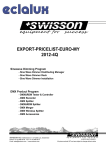
Leader in Electrics & Automation
Variable Frequency Drive / Inverter
Starvert iH
30 - 55kW(40 -75HP) 3 phase 200 - 230Volts
30 - 220kW(40 - 300HP) 3 phase 380 - 400Volts, 440 - 460Volts
Leader in Electrics & Automation
• For your safety, please read user's manual thoroughly before operating.
• Contact the nearest authorized service facility for examination, repair, or adjustment.
• Please contact a qualified service technician when you need maintenance.
Do not disassemble or repair by yourself!
Safety Instructions
• Any maintenance and inspection shall be performed by the personnel having expertise concerned.
www.lgis.com
■ HEAD OFFICE
LG TWIN TOWERS, 20 Yoido-dong, Youngdungpo-gu,
Seoul, 150-721, Korea
Tel. (82-2)3777-4643~4649
Fax. (82-2)3777-4879, 780-4885
http://www.lgis.com
http://www.fasolution.com
Specifications in this catalog are subject to change without notice due to
continuous product development and improvement.
2004. AUG-1
■ Global Network
•LG Industrial Systems Tokyo Office
Japan
Address: 16F, Higashi-Kan, Akasaka Twin Towers 17-22, 2-chome,
Akasaka, Minato-ku Tokyo 107-8470, Japan
Tel: 81-3-3582-9128 Fax: 81-3-3582-0065 e-mail: [email protected]
•LG Industrial Systems Dubai office UAE
Address: P.O.Box-114216, API World Tower, 303B, Sheikh Zayed road, Dubai, UAE.
Tel: 971-4-3328289 Fax: 971-4-3329444 e-mail: [email protected]
•LG-VINA Industrial Systems Co., Ltd Vietnam
Address: LGIS VINA Congty che tao may dien Viet-Hung Dong Anh Hanoi, Vietnam
Tel: 84-4-882-0222 Fax: 84-4-882-0220 e-mail: [email protected]
•LG Industrial Systems Hanoi Office Vietnam
Address: Room C21, 5Th Floor, Horison Hotel, 40 Cat Linh , Hanoi, Vietnam
Tel: 84-4-736-6270/1 Fax: 84-4-736-6269
•Dalian LG Industrial Systems Co., Ltd China
Address: No. 15 Liaohexi 3 Road, economic and technical
development zone, Dalian, China
Tel: 86-411-8731-8210 Fax: 86-411-8730-7560 e-mail: [email protected]
•LG Industrial Trading (Shanghai) Co., Ltd China
Address: Room 1705-1707, 17th Floor Xinda Commercial Building No 322,
Xian Xia Road Shanahai, China
Tel: 86-21-6252-4291 Fax: 86-21-6278-4372 e-mail: [email protected]
•LG Industrial Systems Beijing Office China
Address: Room 303, 3F North B/D, EAS 21 XIAO YUN ROAD,
Dong San Huan Bei Road, Chao Yang District, Beijing, China
Tel: 86-10-6462-3259/4 Fax: 86-10-6462-3236 e-mail: [email protected]
•LG Industrial Systems Shanghai Office China
Address: Room 1705-1707, 17th Floor Xinda Commercial Building
No 318, Xian Xia Road Shanahai, China
Tel: 86-21-6278-4370 Fax: 86-21-6278-4301 e-mail: [email protected]
•LG Industrial Systems Guangzhou Office China
Address: Room 303, 3F, Zheng Sheng Building, No 5-6, Tian He
Bei Road, Guangzhou, China
Tel: 86-20-8755-3410 Fax: 86-20-8755-3408
e-mail: [email protected]
Starvert iH 2002. 4/(02) 2004. 08 Printed in Korea STAFF
Automation Equipment
Overview
Standard features
Contents
Overview
02
Features & Selection Guide
04
Specifications
06
Wiring & Terminal Configuration
08
Keypad & Procedure of Setting Data
10
Program Parameter Descriptions
12
Dimension & Braking unit
16
Driveview 2.0 & Peripheral devices & RFI Filters
18
Dual rated iH,
fits for HVAC applications
with Space Vector Control.
KW / Voltage Ratings:
30-55kW, 200-230VAC, 3 phase
30-220kW, 380-460VAC, 3 phase
Inverter Type : PWM with IGBT
CPU : 32bits high speed DSP
Control method: Volts/Hertz with
Space Vector PWM Technology
CT, VT dual ratings
Enclosure : IP00
2-10kHz Carrier Frequency
0.5-400 Output Frequency
Removable Keypad(Able to read & write parameters)
6 Multi-function Inputs
5 Multi-function Outputs (3 Open-collectors, 2 Relays)
4-20mA Analog Output
DC Injection Braking
Options
Dynamic Braking Units
Communication Board
RS485
F-Net
ModBus-RTU
Device Net
Profibus
Window based operating software(Driveview 2.0)
Application
Fan/Blower
Water/Waste Water Pump
Conveyor
Parking System
Material Handling
Industrial Washing Machine
Packaging machine
Conformity to global standards
UL and cUL listed for North America
CE marked for Europe
Quality process controlled by ISO9001, ISO14000
ISO9001
ISO14000
02
Overview
Standard features
Contents
Overview
02
Features & Selection Guide
04
Specifications
06
Wiring & Terminal Configuration
08
Keypad & Procedure of Setting Data
10
Program Parameter Descriptions
12
Dimension & Braking unit
16
Driveview 2.0 & Peripheral devices & RFI Filters
18
Dual rated iH,
fits for HVAC applications
with Space Vector Control.
KW / Voltage Ratings:
30-55kW, 200-230VAC, 3 phase
30-220kW, 380-460VAC, 3 phase
Inverter Type : PWM with IGBT
CPU : 32bits high speed DSP
Control method: Volts/Hertz with
Space Vector PWM Technology
CT, VT dual ratings
Enclosure : IP00
2-10kHz Carrier Frequency
0.5-400 Output Frequency
Removable Keypad(Able to read & write parameters)
6 Multi-function Inputs
5 Multi-function Outputs (3 Open-collectors, 2 Relays)
4-20mA Analog Output
DC Injection Braking
Options
Dynamic Braking Units
Communication Board
RS485
F-Net
ModBus-RTU
Device Net
Profibus
Window based operating software(Driveview 2.0)
Application
Fan/Blower
Water/Waste Water Pump
Conveyor
Parking System
Material Handling
Industrial Washing Machine
Packaging machine
Conformity to global standards
UL and cUL listed for North America
CE marked for Europe
Quality process controlled by ISO9001, ISO14000
ISO9001
ISO14000
02
Features & Selection Guide
Starvert iH
Space vector PWM technology
User friendly easy straight line programming
The Space vector technology is being adopted in all LG drives. It features outstanding performance in its
control characteristics. It has low total harmonic distortion, low current ripple, low torque ripple, low motor
temperature rise, and better voltage utilization. It is a basic control platform of the iH. The advantages of
Space vector PWM technology are being provided in many applications.
The iH has simple grouping programming flow. It enables quick and easy parameter change
and monitoring through 32 character two line LCD display keypad.
High torque in overall speed range
The iH has 150% torque at low speed. Thus, its torque performance is proved in high duty applications.
Better Efficiency (Low Iron Loss in Motor)
Low Total
Harmonic Distortion
Low Motor Heat (Extended Motor)
Drive rating selection guide
High Voltage Utilization (15.9%)
Low Torque Ripple
Low Current Ripple
Stable & Smooth Operation
High and Stable Torque
30
40
SV030iH-2
SV030iH-4
37
50
SV037iH-2
SV037iH-4
Built-in PI control
45
60
SV045iH-2
SV045iH-4
It is valuable in process control. The built-in PI controller controls flow, temperature, pressure, etc. through
the proportional and integral calculus between the feedback value and reference value in closed loop.
55
75
SV055iH-2
SV055iH-4
75
100
SV075iH-4
90
125
SV090iH-4
110
150
SV110iH-4
Convenient and Various Communication Interface
132
175
SV132iH-4
The iH can be operated with communication interface such as RS485, ModBus-RTU, DeviceNet, Profibus,
and F-Net, in order to be operated in various circumstances. Driveview 2.0 software is a Window based
tool that provides convenience of monitoring and controlling to user. The Driveview 2.0 features a graph
monitor, keypad emulator, parameter editor, and text monitor, to help user`s monitoring and controlling of
drive. It is applicable for all LG drives.
160
215
SV160iH-4
220
300
SV220iH-4
Drive type nomenclature
SV
30
iH
-4
LG Starvert drive
CT / VT Dual Ratings
The iH features dual ratings in order to be used in both of constant torque and variable torque load
conditions. User can pick the most suitable drive through dual ratings for various load conditions. In that
way, user can be prevented from using an overpowered drive.
03
030
30kW
iG5
iG5 series
-2
3 phase 200~230V
037
37kW
iS5
iS5 series
-4
3 phase 380~460V
045
45kW
iH
iH series
.
.
iV5
iV5 series
.
.
220
220kW
04
Specifications
Starvert iH
Specifications 200 ~ 230V Class(40~ 75HP)
Type
1)
Motor rating*
Output ratings
SV030iH-2
SV045iH-2
Type
SV055iH-2
110
132
160
220
55
Constant Torque FLA [A]
46
55
68
83
Variable Torque [HP]
150
200
250
300
350
Constant Torque [kVA]*2)
122
146
180
220
Variable Torque [kW]
110
132
185
220
280
Constant Torque FLA [A]
4)
Constant Torque [kVA]*
183
223
264
325
432
136
166
197
242
322
Variable Torque FLA [A]
4)
Variable Torque [kVA]*
228
264
330
361
477
170
200
246
270
356
122(269)
122(269)
175(386)
1)
Motor rating*
3phase, 200to 230V( 10%)
50 to 60Hz( 5%)
42(93)
42(93)
56(123)
Output ratings
56(123)
SV030iH-4
SV037iH-4
SV045iH-4
SV055iH-4
SV075iH-4
40
50
60
75
100
Constant Torque [kW]
30
37
45
55
75
Variable Torque [HP]
50
60
75
100
125
Variable Torque [kW]
37
45
55
75
90
Constant Torque FLA [A]
3)
Constant Torque [kVA]*
61
75
91
110
152
40
50
60
70
100
Variable Torque FLA [A]
3)
Variable Torque [kVA]*
80
96
115
125
160
52
62
74
80
103
Weight[kg(lbs)]
Constant Torque [HP]
3phase, 440 to 460V( 10%)
Frequency
Output ratings
Max. Frequency
45(99)
63(139)
63(139)
68(150)
SV090iH-4
SV110iH-4
SV132iH-4
SV160iH-4
SV220iH-4
125
150
175
215
300
Constant Torque [kW]
90
110
132
160
220
Variable Torque [HP]
150
175
215
250
350
98(216)
0.5 to 400 Hz
Output Voltage
3 Phase, 0 to Input Voltage
Control Method
Space Vector PWM
Frequency Setting Resolution
Digital Reference: 0.01 Hz (Below 100Hz), 0.1 Hz (Over 100Hz)
Analog Reference: 0.03 Hz / 60Hz
Frequency Accuracy
50 to 60Hz( 5%)
50 to 60Hz( 5%)
98(216)
Common Specifications
3phase, 380 to 400V( 10%)
45(99)
Type
Voltage
Weight[kg(lbs)]
Constant Torque [HP]
Frequency
Digital: 0.01% of Maximum Output Frequency
Analog: 0.1% of Maximum Output Frequency
Control
V/F Ratio
Linear, Non-Linear, User Programmable
Braking Torque (w/o DB)
About 20%
Overload Capacity CT
150% of Rated Current for 1 Minute, 200% for 0.5 Second
Overload Capacity VT
110% of Rated Current for 1 Minute, 150% for 0.5 Second
Torque Boost
Manual Torque Boost (0 to 20%), Auto Torque Boost
Operation Method
Keypad / Terminal / Remote (Optional)
Analog: 0 to 10 V / 4 to 20mA, Digital: Keypad
Variable Torque [kW]
110
132
160
185
280
Frequency Setting
Constant Torque FLA [A]
183
223
264
325
432
Accel / Decel Time
0.1 to 6,000 sec, 8 Pre-Defined (Programmable)
Constant Torque [kVA]*3)
120
145
170
200
280
Multi-Step
8 Preset Operational Speed
Variable Torque FLA [A]
228
264
330
361
477
Jog
Jog Operation
Variable Torque [kVA]*3)
147
170
213
233
307
Operating Function
DC Braking, Frequency Limit, Frequency Jump, Slip Compensation, PI Control, Stall Prevention
Operating Status
Frequency Detection Level, Overload Alarm, Stalling, Over Voltage, Under Voltage,
Voltage
Input ratings
90
75
45
Voltage
Output ratings
300
Constant Torque [kW]
60
37
Type
1)
SV220iH-4
215
50
Specifications 380 ~ 400V Class(40~ 300HP)
Motor Rating*
SV160iH-4
175
30
Input ratings
Input ratings
SV132iH-4
150
40
Weight[kg(lbs)]
Output ratings
SV110iH-4
125
Constant Torque [kW]
Frequency
1)
Motor rating*
SV090iH-4
Constant Torque [HP]
Constant Torque [HP]
Voltage
Input ratings
SV037iH-2
3phase, 380 to 400V( 10%)
Frequency
Weight[kg(lbs)]
Operating
50 to 60Hz( 5%)
98(216)
Drive Overheat, Run, Stop, Constant Speed, Speed Searching
98(216)
122(269)
122(269)
175(386)
Start Signal
Forward, Reverse
Programmable Input
6 Programmable Inputs
Programmable Output
5 Programmable Outputs: 2 Form A Contact (N.O.)
Fault Contact Output (A, C, B) - 250VAC 1A, 30VDC 1A
Programmable I/O
Specifications 440 ~ 460V Class(40~ 300HP)
Type
1)
Motor rating*
Output ratings
Input ratings
Weight[kg(lbs)]
SV030iH-4
SV037iH-4
SV045iH-4
SV055iH-4
SV075iH-4
Constant Torque [HP]
40
50
60
75
100
Constant Torque [kW]
30
37
45
55
75
Variable Torque [HP]
50
60
75
100
Variable Torque [kW]
37
45
55
Constant Torque FLA [A]
4)
Constant Torque [kVA]*
61
75
45
Variable Torque FLA [A]
4)
Variable Torque [kVA]*
80
60
Voltage
*1)Indicates the maximum applicable capacity when using a 4 Pole motor.
*2)Rated kVA ( 3*V*I) is based on 220V.
*3)Rated kVA ( 3*V*I) is based on 380V.
*4)Rated kVA ( 3*V*I) is based on 440V.
05
RPM, Hz, Current, Voltage (Output Pulse: 500Hz, Output Voltage: 0 ~ 10V)
Drive Trip
Over Voltage, Under Voltage, Over Current, Drive Overload, Fuse Open, Ground Fault,
Drive Overheat, Motor Overheat, Main CPU Error.
Protective Functions
Over Current Prevention
125
Instant Power Loss
Less Than 15msec: Continuous Operation, More Than 15msec: Auto Restart (Programmable)
75
90
Ambient Temp.
14°F ~ 104°F (-10°C ~ 40°C), CE Certification: 41°F ~ 104°F (5°C ~ 40°C)
91
110
152
Storage Temp.
-4°F ~ 149°F (-20°C ~ 65°C)
56
68
82
113
96
115
125
160
70
86
93
120
Humidity
Altitude . Vibration
90% RH Max. (Non-Condensing), CE Certification: 5 ~ 85% (Non-Condensing)
Below 3,300ft (1,000m) . Below 5.9m/sec2 (0.6 g)
Air Pressure
86 ~ 106kPa
Application Site
No corrosive gas, combustible gas, oil mist, or dust
Cooling Method
Forced Air Cooling
Enclosure
IP00
International Standards
CE Certified, UL Listed (UL508C)
50 to 60Hz( 5%)
45(99)
4 ~ 20mA
Meter
Stall Prevention
3phase, 440 to 460V( 10%)
Frequency
3 Open Collector Outputs: 24V, 50mA
Analog
45(99)
63(139)
63(139)
68(150)
Operating Conditions
06
Keypad & Procedure of Setting Data
Starvert iH
Keypad
Procedure of Setting Data
LCD Control Panel
PROG
LCD Control Panel
ENTER
32 Character, back lit, LCD display.
The backlight is adjustable.
The Program Button is used to go into programming
ßô To change command frequency from 30.00Hz to 45.50Hz :
mode to change data.
The Enter Button is used to enter changed parameters.
The button is used to move cursor across the display
PROG
in a programming mode.
The Mode Button moves you through
the three program groups : DRV, FUN, I/O
MODE
MODE
PROG
FWD
ENTER
The Up and Down Arrows are used to
REV
search parameters and change data.
RESET
the reverse drive accels or decels.
Press PROG key and the cursor appears on the lowest digit.
DRV
Manual K/K
00 REV 30.00Hz
Press LEFT key once to move digit.
DRV
Manual K/K
00 REV 30.50Hz
Press UP key 5 time.
DRV
Manual K/K
00 REV 30.50Hz
Press SHIFT key once to shift the cursor to next digit.
DRV
Manual K/K
00 REV 35.50Hz
Press UP key 5 time.
DRV
Manual K/K
00 REV 35.50Hz
Press SHIFT key once to shift the cursor to next digit.
DRV
Manual K/K
00 REV 45.50Hz
Press UP key once to make 4.
DRV
Manual K/K
00 REV 45.50Hz
Press ENTER key to store new value.
The Forward Run Button blinks when the forward
drive accels or decels.
STOP
The Stop Button blinks when there is a fault.
RESET
The Reset Button is used to reset faults.
FWD
STOP
The Reverse Run Button blinks when
DRV
Manual K/K
00 REV 30.00Hz
REV
Parameter groups
Group name
LCD Keypad(Upper Left Coner)
Description
Drive Group
DRV
Command frequency, Accel/Decel time Etc. Basic parameters
Function Group
FUN
Maximum frequency, amount of torque boost etc. Basic Related Parameters
Input/Output Group
I/O
Multi-Function terminal settings. Parameters needed for sequence operation
Operation method
Operation Method
Operation using keypad
Function
Run/Stop command and frequency are set only through the keypad.
Function Setting
FUN 01: Key
ENTER
FUN 02: Key
Operation using Control Terminals
Operation using both Keypad
Closing FX or RX terminal performs Run/Stop.
FUN 01: Terminal
Frequency reference is set through V1 or I terminal.
FUN 02: Terminal-1 or Terminal-2
Run/Stop is performed by the keypad. Frequency reference is set through the V1 or I terminal.
FUN 01: Terminal
The same procedure is applied to all other parameters. While the drive is running, the output frequency can be
change to a new command frequency.
*Note : Some parameters cannot be changed while the drive is running
and Control Terminals
FUN 02: Key
Closing FX or RX terminal performs Run/Stop. Frequency reference is set through the keypad.
(refer to the function group table in program parameter descriptions.)
FUN 01: Key
FUN 02: Terminal-1 or Terminal-2
Option
Operation using RS485 communication between drive and computer.
FUN 01: Remote
FUN 02: Remote
I/O 48: RS485
Operation using ModBus RTU communication between drive and PLC.
FUN 01: Remote
FUN 02: Remote
I/O 48: ModBus RTU
Operation using FNet communication between drive and computer.
FUN 01: Remote
FUN 02: Remote
I/O 48: FNet
09
10
Program Parameter descriptions
Starvert iH
Program parameter descriptions
Parameter navigation
1. Drive Group
Drive Group
Function Group
I / O Group
Code [DRV]
00
MODE
DRV Manual K/K
00 FWD 60.00Hz
MODE
FUN
00
Jump code
41
MODE
I/O
00
01
02
03
04
05
06
Jump code
1
Setting Range
Units
Factory
Default
Adjustable
during run
Cmd. Freq
0 to FUN04
0.01
0.00 [Hz]
Yes
Acc.time
Dec. time
Current
Speed
Power
Fault
0 to 6000 [sec]
0 to 6000 [sec]
The load current in RMS
The motor speed in RPM
Inverter Output Power
-
0.1
0.1
-
30.0 [sec]
60.0 [sec]
- [A]
- [rpm]
-[kW]
-
Yes
Yes
-
Setting Range
Units
Factory
Default
Adjustable
during run
Description of Drive Group
Keypad Display
Output Frequency(During Run)or
Reference Frequency(During Stop)
Acceleration Time
Deceleration Time
Output Current
Output Speed
Output Power Display
Fault Display
2. Function Group
MODE
MODE
MODE
Code [FUN]
DRV
01
Acc. time
30.0sec
FUN
01
Freq. set
Key
MODE
DRV
02
Dec. time
60.0sec
FUN
02
Current
x.x A
Run/stop set
Key
FUN
03
Speed
xxxrpm
MODE
I/O
03
P3 input
SPD_H
Freq. max
60.00Hz
MODE
I/O
04
P4 input
ACCT_L
MODE
FUN
05
Freq. base
60.00 Hz
MODE
I/O
05
.
.
.
.
MODE
DRV
06
P2 input
SPD_M
MODE
FUN
04
Power
57.5kW
I/O
02
Run prohibit
None
MODE
DRV
05
MODE
MODE
MODE
DRV
04
P1 input
SPD_L
MODE
MODE
DRV
03
I/O
01
P5 input
ACCT_M
.
.
.
.
Fault
No fault
MODE
MODE
Description of Function Group
Keypad Display
00
Jump to Desired Code #
Jump Code
1 to 98
1
41
Yes
01
Frequency Setting Mode
Freq.set
Key,Terminal, Remote
-
Key
No
02
Run / Stop Mode Selection
Run/Stop set
Key, Terminal-1,Terminal-2, Remote
-
Key
No
03
Run Prevention
Run prohibit
None, FWD disable, REV disable
-
None
No
04
Maximum Frequency Output Set Point
Freq.max
40 to 400 [Hz]
0.01
60 [Hz]
No
05
Base Frequency
Freq.base
40 to FUN 04
0.01
60 [Hz]
No
06
Starting Frequency
Freq.start
0.5 to 5[Hz]
0.01
0.5 [Hz]
No
07
Starting Frequency Hold Time
Hold time
0 to 10 [sec]
0.1
0.0 [sec]
Yes
08
Volts / Hz Pattern
V/F pattern
Linear, 2.0(Squared), User, Auto
-
Linear
No
09
Torque Boost in Forward Direction
Fwd boost
0 to 20 [%]
1
2 [%]
Yes
10
Torque Boost in Reverse Direction
Rev boost
0 to 20 [%]
1
2 [%]
Yes
11
Acceleration Pattern
Acc. pattern
Linear, S-curve,U-curve
-
Linear
No
12
Deceleration Pattern
Dec. pattern
Linear, S-curve,U-curve
-
Linear
No
13
Output Voltage Adjustment
Volt control
40 to 110 [%]
1
100 [%]
No
14
Energy Savings Level
Energy save
30 to 100 [%]
1
100 [%]
Yes
15
Stop Mode Selection
Stop mode
Decel, DCBR, Free Run
-
Decel
No
16
User V/F - Frequency 1
User-1f
0 to 30 [Hz]
0.01
10.00 [%]
No
17
User V/F - Voltage 1
User-1v
0 to 50 [%]
1
15 [%]
No
18
User V/F - Frequency 2
User-2f
FUN 16 to FUN 04
1
30.00 [%]
No
19
User V/F - Voltage 2
User-2v
FUN 17 to 100 [%]
1
50 [%]
No
20
Analog Speed Input Selection
V-I mode
V1, I, V1+I, V2
-
V1
No
21
Analog Speed Input Filter Gain
Filter gain
1 to 100 [%]
1
25 [%]
Yes
22
Analog Speed Input Gain
Analog gain
50 to 250 [%]
1
100 [%]
Yes
23
Analog Speed Input Bias
Analog bias
0 to 200 [%]
1
0 [%]
Yes
24
Analog Speed Input Direction
Analog dir
Direct, Invert
-
Direct
Yes
25
Frequency Limit Selection
Freq. limit
No, Yes
-
No
No
26
Frequency High Limit Selection
F-limit high
0 to FUN 04
0.01
60.00 [Hz]
No
27
Frequency Low Limit Selection
F-limit low
0 to FUN26
0.01
0.00 [Hz]
No
28
Jump Frequency Selection
Freq. jump
No, Yes
-
No
No
29
Jump Frequency 1
Freq. jump 1f
0 to FUN 04
0.01
10.00 [Hz]
No
30
Jump Frequency 2
Freq. jump 2f
0 to FUN 04
0.01
20.00 [Hz]
No
31
Jump Frequency 3
Freq. jump 3f
0 to FUN 04
0.01
30.00 [Hz]
No
32
Jump Frequency Bandwidth
Freq. band
0 to 30 [Hz]
0.01
5.00 [Hz]
No
33
DC Injection Braking Frequency
DC-br freq
0 to 60 [Hz]
0.01
0.5 [Hz]
Yes
34
DC Injection Braking On-Delay Time
DC-br block
0.5 to 5[sec]
0.1
2 [sec]
Yes
35
DC Injection Braking Time
DC-br time
0.1 to 25.0 [sec]
0.1
0.5 [sec]
Yes
36
DC Injection Braking Voltage
DC-br value
1 to 20 [%]
1
1 [%]
Yes
37
Slip Compensation
Slip compen.
No, Yes
-
No
Yes
38
Rated Motor Slip
Rated slip
0 to 5 [Hz]
0.01
Yes
39
Rated Motor Current (in RMS)
M-rated cur.
0.1 to 999[A]
0.1
0.00 [Hz]
9)
103.0 [A]*
40
No Load Motor Current in RMS
No-load cur.
0.1 to 300 [A]
0.1
0.1 [A]
Yes
41
Inverter Capacity
Inv Capacity
SV030iH-2
-
10)
SV030iH-2*
Yes
No
SV037iH-2
FUN
98
Para. lock
0
I/O
61
FN:St.ID
1
......
SV220iH-4
42
Number of Auto Restart
Retry number
0 to 10
1
0
Yes
43
Delay Time Before Auto Restart
Retry time
0 to 10 [sec]
0.1
1.0[sec]
Yes
44
Fault Output Relay(A, B, C)
Relay mode
Retry0, All Trips,
-
Retry 0
Yes
LV+Retry0, LV+All Trips
11
12
Program Parameter descriptions
Starvert iH
Program parameter descriptions
3. I / O Group
2. Function Group
Code [FUN]
45
Code [I/O]
Description of Function Group
Keypad Display
Stall mode
Stall Prevention Mode
Setting Range
Units
None, Acc, Steady, Acc + Steady, Dec,
-
Acc + Dec, Dec + Steady,
Factory
Default
Adjustable
during run
None
Yes
Acc + Dec+Steady
46
Stall level
Stall Prevention Level
47
OL level
Overload Warning Level
48
Overload Warning Hold Time
OL time
49
Over Current Trip Limit Level
OC lim level
50
Over Current Limit Time
OC lim. Time
51
Electronic Thermal Selection
ETH select
52
Electronic Thermal Level
ETH level
53
Electronic Thermal Characteristic
Motor type
(Motor Type) Selection
CT: 30 to 150 [%]
1
150 [%]
Yes
VT: 30 to 150 [%]
1
110 [%]
Yes
CT: 30 to 150 [%]
1
150 [%]
Yes
VT: 30 to 110 [%]
1
110 [%]
Yes
1 to 30 [sec]
1
10 [sec]
Yes
CT: 30 to 200 [sec]
1
160 [%]
Yes
VT: 30 to 150 [sec]
1
110 [%]
Yes
0 to 60 [sec]
0.1
60 [sec]
Yes
No, Yes
-
No
Yes
30 to 150 [%]
1
150 [%]
Yes
General,
-
General
Yes
Special
54
Number of Motor Poles
Pole number
55
IPF (Instant Power Failure)
IPF select
Restart Selection
2 to 12
1
4
Yes
No,
-
No
Yes
Yes
56
Speed Search Acceleration Time
SS acc. time
0.1 to 600 [sec]
0.1
5 [sec]
Yes
57
Speed Search Deceleration Time
SS dec. Time
0.1 to 600 [sec]
0.1
10 [sec]
Yes
58
Speed Search Gain
SS gain
0 to 200 [%]
1
100 [%]
Yes
59
Restart after Fault Reset Selection
RST-restart
No, Yes
-
No
Yes
60
Power-On Start Selection
Power on st
No,Yes
-
No
Yes
61
Carrier Frequency
Carrier Freq
2 to 10 [Hz]
1
11)
6 [Hz]*
No
62
PI Control Selection
PI-control
No,Yes
-
No
No
63
PI Proportional Gain
P-gain
1 to 30000
1
10
Yes
64
PI Integral Gain
I-gain
1 to 30000
1
50
Yes
65
PI Feedback Selection
PI-fb select
I, V1, V2
-
I
No
66
PI Feedback Filter Gain
PI-fb filt.G
1 to 100 [%]
1
25 [%]
Yes
67
PI Feedback Gain
PI-fb gain
50 to 250 [%]
0.1
100.0 [%]
Yes
68
PI Feedback Bias
PI-fb bias
0 to 200 [%]
0.1
100.0 [%]
Yes
69
PI Feedback Direction
PI-fb dir
Direct,Invert
-
Direct
No
70
PI I Gain Scale
I_term scale
1 to 100 [%]
1
100 [%]
Yes
71
PI Controller Error Direction
PI error dir
Direct,Invert
-
Direct
No
72
12)
94*
PI Control Bypass
Regul bypass
No, Yes
-
No
No
CT/VT Selection
CT/VT
Constant Trq,Variable Trq
-
Constant Trq
No
95
Read Parameters into Keypad
No,
-
No
No
Para. Read
from Drive
Yes
96
Write Parameters to Drive from Keypad
Para. Write
No,Yes
-
No
No
97
Initialize Parameters to Factory
Para. Init
No,Yes
-
No
No
Para. Lock
0 to 255
1
0
Yes
Default Settings
98
Parameter Write Protection
*9) Default value depends on the drive capacity.
10)
* FUN 41 is set at its drive capacity before shipping outside. However, drive loses its capacity information after parameter initialization in FUN 97.
If the parameters are initialized, be sure to re-set the drive capacity to the right capacity.
*11)Carrier Frequency according to the drive Capacity (The Carrier Frequency is set to 3kHz for VT Rating)
type
SettingRange
Factory Default
SV030iH-2
2 to 10
6kHz
SV075iH-4
2 to 7
6kHz
SV037iH-2
2 to 10
6kHz
SV090iH-4
2 to 6
6kHz
SV045iH-2
2 to 8
6kHz
SV110iH-4
2 to 6
6kHz
SV055iH-2
2 to 8
6kHz
SV132iH-4
2 to 5
5kHz
SV030iH-4
2 to 10
6kHz
SV160iH-4
2 to 4
4kHz
SV037iH-4
2 to 10
6kHz
SV220iH-4
2 to 4
4kHz
SV045iH-4
2 to 8
6kHz
SV315iH-4
2 to 4
4kHz
SV055iH-4
2 to 8
6kHz
SV375iH-4
2 to 4
4kHz
*12)VT is available only for 440V class inverter.
13
type
SettingRange
Factory Default
00
01
02
03
04
05
06
07
08
09
10
11
12
13
14
15
16
17
18
19
20
21
22
23
24
25
26
27
28
29
30
31
32
33
34
Description of I / O Group
Units
Factory
Default
Adjustable
during run
0 to FUN 04
0 to FUN 04
0 to FUN 04
0 to FUN 04
0 to FUN 04
0 to FUN 04
0 to FUN 04
0 to FUN 04
0 to 6000 [sec]
0 to 6000 [sec]
0 to 6000 [sec]
0 to 6000 [sec]
0 to 6000 [sec]
0 to 6000 [sec]
0 to 6000 [sec]
0 to 6000 [sec]
0 to 6000 [sec]
0 to 6000 [sec]
0 to 6000 [sec]
0 to 6000 [sec]
0 to 6000 [sec]
0 to 6000 [sec]
Voltage,Current
1
0.01
0.01
0.01
0.01
0.01
0.01
0.01
0.01
0.1
0.1
0.1
0.1
0.1
0.1
0.1
0.1
0.1
0.1
0.1
0.1
0.1
0.1
-
1
SPD_L
SPD_M
SPD_H
ACCT_L
ACCT_M
ACCT_H
STEP_L
STEP_M
STEP_H
COMM
COMM
30.00 [Hz]
10.00 [Hz]
20.00 [Hz]
30.00 [Hz]
40.00 [Hz]
50.00 [Hz]
46.00 [Hz]
37.00 [Hz]
1.0 [sec]
1.0 [sec]
2.0 [sec]
2.0 [sec]
3.0 [sec]
3.0 [sec]
4.0 [sec]
4.0 [sec]
5.0 [sec]
5.0 [sec]
6.0 [sec]
6.0 [sec]
7.0 [sec]
7.0 [sec]
Voltage
Yes
No
No
No
No
No
No
No
No
No
No
No
Yes
Yes
Yes
Yes
Yes
Yes
Yes
Yes
Yes
Yes
Yes
Yes
Yes
Yes
Yes
Yes
Yes
Yes
Yes
Yes
Yes
Yes
Yes
Analog adj.
0 to 120 [%]
1
100 [%]
Yes
FM adj.
DAC adj.
FST-freq.
FDT-freq.
FDT-band
Mul. Factor
0 to 120 [%]
0 to 120 [%]
0 to FUN 04
0 to FUN 04
0 to 30 [Hz]
0 to 999
1
1
0.1
0.1
0.1
1
100 [%]
100 [%]
0.50 [Hz]
60.00 [Hz]
1.00 [Hz]
100
Yes
Yes
No
No
No
Yes
Div. factor
1 to 999
1
100
Yes
Ter. Input
Ter. Output
S/W version
Last fault 1
Fault Status,
Freq. at Fault,
Current at Fault
None,RS485,ModBus RTU,FNet
None, MMC
1 to 32
1200,2400,4800,9600,19200
0 to 60 [sec]
0 to 10 [Hz]
0 to 225
0 to 225
0 to 225
100,500,512,1000,1024,2000,2048,4000
None,Freq. 1,Freq. 2
Freq.,Voltage,Current
80 to 120 [%]
1 to 63
-
2.00
-
Yes
1
0.1
0.01
1
1
1
1
1
None
None
1
9600 BPS
10.0 [Sec]
5.00 [Hz]
1
1
100
512 Pulse
Freq. 1
Freq.
100 [%]
1
Yes
No
No
Yes
Yes
Yes
Yes
Yes
Yes
Yes
Yes
Yes
Yes
Yes
No
Keypad Display
Jump Code
P1 Input
P2 Input
P3 Input
P4 Input
P5 Input
P6 Input
OC1 Output
OC2 Output
OC3 Output
AUX1 Output
AUX2 Output
Jog freq.
Step freq-1
Step freq-2
Step freq-3
Step freq-4
Step freq-5
Step freq-6
Step freq-7
Acc time-1
Dec time-1
Acc time-2
Dec time-2
Acc time-3
Dec time-3
Acc time-4
Dec time-4
Acc time-5
Dec time-5
Acc time-6
Dec time-6
Acc time-7
Dec time-7
Analog meter
43
44
45
46
Jump to Desired Code #
Multi-function Input 1(P1 terminal)
Multi-function Input 2 (P2 terminal)
Multi-function Input 3 (P3 terminal)
Multi-function Input 4 (P4 terminal)
Multi-function Input 5 (P5 terminal)
Multi-function Input 6 (P6 terminal)
Multi-function Output 1 (OC1 terminal)
Multi-function Output 2 (OC2 terminal)
Multi-function Output 3 (OC3 terminal)
Multi-function Output 4 (Aux.1 Relay term.)
Multi-function Output 5 (Aux. 2 Relay term.)
Jog Frequency
Step Speed 1
Step Speed 2
Step Speed 3
Step Speed 4
Step Speed 5
Step Speed 6
Step Speed 7
Acceleration Time 1
Deceleration Time 1
Acceleration Time 2
Deceleration Time 2
Acceleration Time 3
Deceleration Time 3
Acceleration Time 4
Deceleration Time 4
Acceleration Time 5
Deceleration Time 5
Acceleration Time 6
Deceleration Time 6
Acceleration Time 7
Deceleration Time 7
Output Voltage / Current Meter
(LM Meter) Selection
Output Voltage / Current Meter
(LM Meter) Adjustment (15V Pulse)
FM Meter Output Adjustment (15V Pulse)
IO Meter Output Adjustment (4 to 20mA)
Frequency Steady Level
Frequency Detection Level
Frequency Detection Bandwidth
Multiplier Constant for Speed
Display in 'DRV 04'
Divider Constant for Speed Display
in 'DRV 04'
Status of Input Terminals
Status of Output Terminals
Software Version
Fault History 1
47
48
49
50*13)
51
52
53
54
55
56
57
58
59
60
61
Fault History 2
Option 1 Selection
Option 2 Selection
Drive number for Option
Baud rate for Option
Communication Timeout
PG Slip Frequency for PG Option
PG-P Gain for PG Option
PG-I Gain for PG Option
PG-Filter Gain for PG Option
Encoder Selection for PG Option
Digital Input for DI/DA Option
Analog Output for DI/DA Option
Analog Output Adjustment
Drive Number for FNet
Last fault 2
Option 1
Option 2
Inv. Number
Baud-rate
Comm. Timeout
PG Slip Freq
PG. P-Gain
PG. I-Gain
PG. F-Gain
Enc pulse
DI Mode
DA Mode
DA adj.
FN:St.ID
35
36
37
38
39
40
41
42
*13)Operation related parameters(FUN50 ~ FUN61) - Please refer to specific option manual.
Setting Range
1 to 60
SPD_L,SPD_M,SPD_H,
JOG,ACCT_L,ACCT_M,
ACCT_H,UP,DOWN,
HOLD,DIS_OPT,
COMM_CONN,EXT_DCBR,
EXT_TRIP - SPD_L
FST_LO,FST_HI,FDT_HI,
FDT_PULSE,FDT_BAND,
OL,STALL,LV,RUN,COMM,
STEP_L,STEP_M,STEP_H,
14
Dimension & Braking unit
Starvert iH
Braking unit
Dimension(mm)
Model name
SV037DBH-2
SV037DBH-4
SV075DBH-4
Max. DC Input Voltage
DC 400V (200V class)
Capacity
37kW / 200V
37kW / 400V
75kW / 400V
Required resistor
5kW 3Ω
5kW 12Ω
10kW 6Ω
VARIABLE FREQUENCY DRIVE
Applicable type
& braking
resistor combination
H2 H1
SV030iH-2
1 unit (1x5kW 3Ω)
SV037iH-2
1 unit (1x5kW 3Ω)
SV045iH-2
Parallel 2 units (2x5kW 3Ω)
SV055iH-2
Parallel 2 units (2x5kW 3Ω)
DC 800V (400V class)
SV030iH-4
1 unit (1x5kW 12Ω)
SV037iH-4
1 unit (1x5kW 12Ω)
SV045iH-4
1 unit (2x5kW 12Ω)
SV055iH-4
1 unit (2x5kW 12Ω)
SV075iH-4
1 unit (2x5kW 12Ω)
SV090iH-4
Parallel 2 units (4x5kW 12Ω)
SV110iH-4
Parallel 2 units (4x5kW 12Ω)
SV132iH-4
Parallel 2 units (4x5kW 12Ω)
SV160iH-4
Parallel 2 units (4x5kW 12Ω)
SV220iH-4
!
Braking torque 150%
150%
Enable duty 5% ED
5% ED
Output signal
Fault output contact, Slave control signal
Protection
Heat sink overheat, Inverter Overheat
W3
W2
D2
W1
D1
RS-485 / Modbus-RTU
Category
Item
Performance
Hardware
RS485
Transmission form
Multi-drop Link System
Applicable type
iH series
Computer
PC or FA computer (needs RS232-485 converter)
Number of drives
Maximum 32 drives connectable
Transmission distance
Max. 1200m
Installation
Power Supply
Communication
Communication speed
(unit : mm)
Class
200-230V
380-460V
15
Type
W1
W2
W3
H1
H2
D1
D2
SV030iH-2
375
360
275
615
593.5
277.5
230.5
SV037iH-2
375
360
275
615
593.5
277.5
230.5
SV045iH-2
375
360
275
780
758.5
300.7
230.5
SV055iH-2
375
360
275
780
758.5
300.7
230.5
SV030iH-4
350
319.2
270
680
662
308.2
256.6
SV037iH-4
350
319.2
270
680
662
308.2
256.6
SV045iH-4
375
359.6
275
780
760.5
326
259
SV055iH-4
375
359.6
275
780
760.5
326
259
SV075iH-4
375
359.6
275
780
760.5
326
259
SV090iH-4
530
507
430
780
762
335
286.2
SV110iH-4
530
507
430
790
762
335
286.2
SV132iH-4
530
507
430
1000
982
345
298
SV160iH-4
530
507
430
1000
982
345
298
SV220iH-4
680
649
540
998
968.5
403
343
Specifications
Communication method
On control PCB inside the drives
Control
5V DC from drive main PCB
Communication
5V DC. Max.100mA (contained in Communication card)
19200/9600/4800/2400/1200 bps selectable
Control procedure
Asynchronous communication system
Communication system
Half duplex system
Character system
RS485 : ASCII (8 bit) / ModBus-RTU : Binary
Stop bit length
1 bit
Sum check
2 bytes
Parity check
None
F-net
Item
Specifications
Communication speed
1M bps
Communication type
Manchester Biphase-L, Frame Synchronous type
Cable
Twisted Pair Shielded Cable
Name : LIREC-AMESB 1ø(PC 717 6705)
Manufacturer : LG Cable
No. of node
Max. 64 per line
Distance
Max. 750m
Frame Format
FieldBus (IEC TC65/SC65C/WG6 65C 90.8)
16
Starvert iH
Driveview 2.0 & RFI Filter
RFI Filter
Driveview 2.0
IH Series
Versatile, Easy-to-Use Software for LG Drives
type
Provides Intuitive Means for Monitoring, Control and Commissioning of Drives
Designed for Microsoft Windows 95 or later
Graphic Monitor
Parameter Editor
Power
Code
Voltage
Current
THREE PHASE
Runs on RS-232/485 Serial Network Connection
Keypad Emulator
Standard Filter
Leakage
Current
Dimensions
L
W
H
Mounting
Y
X
Weight
Mount
Output
Chokes
Nom. MAX.
SV030iH-2
30kW
FE-T150-2
150A
250VAC
1.3A 150A
480 X 200 X 160
468 X 166
--
FS-3
SV037iH-2
37kW
FE-T170-2
170A
250VAC
1.3A 150A
480 X 200 X 160
468 X 166
--
FS-3
SV045iH-2
45kW
FE-T230-2
230A
250VAC
1.3A 150A
580 X 250 X 205
560 X 170
--
FS-4
SV055iH-2
55kW
FE-T280-2
280A
250VAC
1.3A 150A
580 X 250 X 205
560 X 170
--
FS-4
SV030iH-4
30kW
FE-T070-2
70A
380VAC
1.3A 150A
350 X 180 X 90
338 X 146
--
FS-3
SV037iH-4
37kW
FE-T100-2
100A
380VAC
1.3A 150A
425 X 200 X 130
408 X 166
--
FS-3
SV045iH-4
45kW
SV055iH-4
55kW
FE-T120-2
120A
380VAC
1.3A 150A
425 X 200 X 130
408 X 166
--
FS-3
SV075iH-4
75kW
FE-T170-2
170A
380VAC
1.3A 150A
480 X 200 X 160
468 X 166
--
FS-3
SV090iH-4
90kW
FE-T230-2
230A
380VAC
1.3A 150A
580 X 250 X 205
560 X 170
--
FS-4
SV110iH-4
110kW
SV132iH-4
132kW
FE-T280-2
280A
380VAC
1.3A 150A
580 X 250 X 205
560 X 170
--
FS-4
SV160iH-4
160kW
FE-T400-2
400A
380VAC
1.3A 150A
700 X 370 X 250
640 X 300
--
FS-4
SV220iH-4
220kW
FE-T480-2
480A
380VAC
1.3A 150A
700 X 370 X 250
640 X 300
--
FS-4
Text monitor
FF Series (Footprint)
FE Series (Standard)
H
H
Y
X
RED
W
CARGA
Y
W
X
L
L
Peripheral devices
17
FS Series (output chokes)
Power
Earth Line
terminal wire(mm2)
(mm2)
GMC-150
60
22
0.35mH, 152.0A
0.08mH, 134.2A
150A
GMC-180
60
22
0.30mH, 180.0A
0.07mH, 160.6A
200A
ABS403/300
GMC-220
100
38
0.28mH, 221.0A
0.06mH, 198.0A
250A
55
ABS403/350
GMC-300
100
38
0.25mH, 270.0A
0.05mH, 242.0A
300A
30
ABS203/125
GMC-85
22
14
1.19mH, 76.0A
0.33mH, 67.1A
100A
SV037iH-4
37
ABS203/150
GMC-100
22
14
0.98mH, 93.0A
0.27mH, 82.5A
100A
SV045iH-4
45
ABS203/175
GMC-125
38
22
0.89mH, 112.0A
0.22mH, 100.1A
100A
SV055iH-4
55
ABS203/225
GMC-150
38
22
0.75mH, 135.0A
0.18mH, 121.0A
150A
SV075iH-4
75
ABS203/225
GMC-180
60
22
0.44mH, 187.0A
0.13mH, 167.2A
200A
SV090iH-4
90
ABS203/300
GMC-220
60
38
0.35mH, 225.0A
0.11mH, 201.3A
250A
SV110iH-4
110
ABS403/300
GMC-300
80
38
0.30mH, 274.0A
0.09mH, 245.3A
300A
SV132iH-4
132
ABS/403/400
GMC-400
100
38
0.26mH, 324.0A
0.08mH, 290.4A
300A
SV160iH-4
Type
D
W
H
X
O
160
ABS603/500
GMC-400
100
60
0.22mH, 399.0A
0.06mH, 357.5A
400A
SV220iH-4
FS-1
21
85
46
7-
5
220
ABS603/600
GMC-600
100x2
60
500A
FS-2
28.5
105
62
90
5
FS-3
48
150
110
125 x 30
5
FS-4
58
200
170
180 x 45
5
Type
kW
Breaker
SV030iH-2
30
ABS203/225
SV037iH-2
37
ABS203/225
SV045iH-2
45
SV055iH-2
SV030iH-4
Magnetic contactor
DC reactor
AC reactor
Fuse
D H
Y
X
W
18
Leader in Electrics & Automation
Variable Frequency Drive / Inverter
Starvert iH
30 - 55kW(40 -75HP) 3 phase 200 - 230Volts
30 - 220kW(40 - 300HP) 3 phase 380 - 400Volts, 440 - 460Volts
Leader in Electrics & Automation
• For your safety, please read user's manual thoroughly before operating.
• Contact the nearest authorized service facility for examination, repair, or adjustment.
• Please contact a qualified service technician when you need maintenance.
Do not disassemble or repair by yourself!
Safety Instructions
• Any maintenance and inspection shall be performed by the personnel having expertise concerned.
www.lgis.com
■ HEAD OFFICE
LG TWIN TOWERS, 20 Yoido-dong, Youngdungpo-gu,
Seoul, 150-721, Korea
Tel. (82-2)3777-4643~4649
Fax. (82-2)3777-4879, 780-4885
http://www.lgis.com
http://www.fasolution.com
Specifications in this catalog are subject to change without notice due to
continuous product development and improvement.
2004. AUG-1
■ Global Network
•LG Industrial Systems Tokyo Office
Japan
Address: 16F, Higashi-Kan, Akasaka Twin Towers 17-22, 2-chome,
Akasaka, Minato-ku Tokyo 107-8470, Japan
Tel: 81-3-3582-9128 Fax: 81-3-3582-0065 e-mail: [email protected]
•LG Industrial Systems Dubai office UAE
Address: P.O.Box-114216, API World Tower, 303B, Sheikh Zayed road, Dubai, UAE.
Tel: 971-4-3328289 Fax: 971-4-3329444 e-mail: [email protected]
•LG-VINA Industrial Systems Co., Ltd Vietnam
Address: LGIS VINA Congty che tao may dien Viet-Hung Dong Anh Hanoi, Vietnam
Tel: 84-4-882-0222 Fax: 84-4-882-0220 e-mail: [email protected]
•LG Industrial Systems Hanoi Office Vietnam
Address: Room C21, 5Th Floor, Horison Hotel, 40 Cat Linh , Hanoi, Vietnam
Tel: 84-4-736-6270/1 Fax: 84-4-736-6269
•Dalian LG Industrial Systems Co., Ltd China
Address: No. 15 Liaohexi 3 Road, economic and technical
development zone, Dalian, China
Tel: 86-411-8731-8210 Fax: 86-411-8730-7560 e-mail: [email protected]
•LG Industrial Trading (Shanghai) Co., Ltd China
Address: Room 1705-1707, 17th Floor Xinda Commercial Building No 322,
Xian Xia Road Shanahai, China
Tel: 86-21-6252-4291 Fax: 86-21-6278-4372 e-mail: [email protected]
•LG Industrial Systems Beijing Office China
Address: Room 303, 3F North B/D, EAS 21 XIAO YUN ROAD,
Dong San Huan Bei Road, Chao Yang District, Beijing, China
Tel: 86-10-6462-3259/4 Fax: 86-10-6462-3236 e-mail: [email protected]
•LG Industrial Systems Shanghai Office China
Address: Room 1705-1707, 17th Floor Xinda Commercial Building
No 318, Xian Xia Road Shanahai, China
Tel: 86-21-6278-4370 Fax: 86-21-6278-4301 e-mail: [email protected]
•LG Industrial Systems Guangzhou Office China
Address: Room 303, 3F, Zheng Sheng Building, No 5-6, Tian He
Bei Road, Guangzhou, China
Tel: 86-20-8755-3410 Fax: 86-20-8755-3408
e-mail: [email protected]
Starvert iH 2002. 4/(02) 2004. 08 Printed in Korea STAFF
Automation Equipment