1
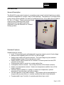
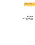
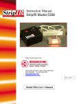
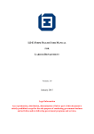
Instruction Manual
ControlIR 915
Another quality product from:
7128 Shady Oak Road • Eden Prairie, MN 55344
(952) 949-9009 Fax (952) 949-9559
www.researchinc.com
[email protected]
Rev.052909
Contents
Contents Introduction ..................................................................................................................................... 1 General Description .................................................................................................................... 1 Standard Features ........................................................................................................................ 1 Optional Features ........................................................................................................................ 2 Safety .............................................................................................................................................. 3 Installation....................................................................................................................................... 4 Mounting the System .................................................................................................................. 4 Wiring Connections .................................................................................................................... 5 Power Wiring Connections ..................................................................................................... 6 Control Connections ................................................................................................................... 6 Cooling Flow On/Off Relay Output ....................................................................................... 6 Cooling Flow Switch Interlock ............................................................................................... 6 Heater Over-Temperature Thermo-switch Interlock .............................................................. 6 Remote Interlock Switch......................................................................................................... 7 Heater Open Switch Interlock ................................................................................................. 7 Remote Setpoint Input ............................................................................................................ 7 Temperature Control Option Connections (Option Codes TCT & TCP) ............................... 7 Operating Instructions..................................................................................................................... 9 Controls and Indicators ............................................................................................................... 9 Main Disconnect Switch ......................................................................................................... 9 Heater ON/OFF Switch........................................................................................................... 9 Cooling ON/OFF Switch ........................................................................................................ 9 Heater On Indicator................................................................................................................. 9 Cooling On Indicator .............................................................................................................. 9 Heater Over Temperature Indicator ........................................................................................ 9 Lamp-Out Indicator .............................................................................................................. 10 Remote/Local Setpoint Switch ............................................................................................. 10 Local Setpoint Potentiometer ................................................................................................ 10 Load Volts Indicator (Option Code VM).............................................................................. 10 Temperature Control Option ..................................................................................................... 11 Setup Summary ..................................................................................................................... 11 Theory of Operation .................................................................................................................. 11 Principles of SCR Power Control ......................................................................................... 11 Principles of Phase Angle Control ........................................................................................ 12 Maintenance & Troubleshooting .................................................................................................. 16 Routine Maintenance ................................................................................................................ 16 Troubleshooting ........................................................................................................................ 16 Calibration................................................................................................................................. 17 Power Controller ................................................................................................................... 17 Panel Voltmeter Calibration ................................................................................................. 17 Temperature Controller Option............................................................................................. 18 Line Voltage Re-Configuration ................................................................................................ 18 Section 1
Introduction
General Description
The Model 915 power control system is a complete power control “solution” featuring a number
of elements integrated into a single, ready-to-install package. The Model 915 is a single-phase
power control system available in a variety of configurations from 120 to 480 volts and rated at
20-, 40-, or 70-amps. These systems are ideally
suited for many industrial power control
applications and have been specifically
optimized for use with Research Inc. infrared
heating systems.
Standard Features
Standard features include:
• Local 10 turn potentiometer with digital dial for precise manual control of load voltage.
• Remote control capability with a 0-5 VDC or 0-20 mA signal.
• Heater power switch with remote interlocks. The load voltage may be enabled or
disabled without turning off the main discount switch.
• Heater ON/OFF switch controls an AC contactor to remove power from the SCR
controller and the load.
• Cooling power switch to control air or water cooling flow.
• Cooling flow interlock contacts. Low cooling flow turns off the heater contactor.
• Heater over temperature contacts. Heater over temperature condition turns off the
heater contactor.
• Indicators lights for heater on, cooling on, heater over temperature, optional
temperature controller alarm and lamp-out alarm.
• Fail safe operation of the heater contactor. The contactor will not automatically reenergize after a power failure, or an alarm condition that shuts down the heater.
• Programmable Logic Controller for operating and alarm logic control.
Page 1 of 21
Optional Features
The following options are available:
Automatic Temperature Control Option
The automatic temperature control option allows the power level to be adjusted based on an
entered temperature setting for the process. The temperature controller uses PID type control
and is pre-wired for a “K” type thermocouple (option code TCT) or a 4/20mA pyrometer signal
(option code TCP).
Voltmeter Option
The true RMS load voltage is displayed with a digital meter. A true RMS voltage transmitter is
provided for isolation and operator safety.
Lamp-out Detection Option
The lamp out detection option is designed to detect a lamp failure or load loss when using
multiple infrared heaters or zones of lamps in a single heater. The lamp out indicator flashes
during this condition.
Page 2 of 21
Section 2
Safety
!WARNING!
Hazardous voltages are present at the main disconnect switch and load terminals. Setting the
setpoint potentiometer or control signal to minimum does NOT eliminate these hazardous
voltages.
Always remove AC line voltage from the system before making contact with internal
assemblies, line or load wiring, or fuses. Also remove AC line voltage from the system before
making connections, equipment changes, or resistance measurements.
!CAUTION!
Up to 480 volts AC is present within the power control solution system.
Do not make any wiring connections when power is applied.
Disconnect power before performing any maintenance or service to the system.
Use extreme caution when adjusting calibration potentiometers on modules when power is
applied.
Always use an isolated oscilloscope for checking waveforms.
Page 3 of 21
Section 3
Installation
This section describes how to install and wire the Model 915 power control system. The
features and options mentioned here are identified in the model number found inside the
enclosure.
!WARNING!
Hazardous voltages are present at the main disconnect switch and load terminals. Setting the
setpoint potentiometer or control signal to minimum does NOT eliminate these hazardous
voltages.
Always remove AC lien voltage from the system before making contact with the internal
assemblies, line or load wiring, or fuses. Also remove AC line voltage from the system before
making connections, equipment changes, or resistance measurements.
Mounting the System
The Model 915 Power Control System may be mounted to a wall with the supplied brackets,
on a stand, or bench. The Model 915 must be mounted in a vertical position. When mounting
to a wall, the top of the enclosure should not be over 74 inches (1880 mm) above the floor.
Figure 3-1 shows the mounting dimensions using the supplied brackets. Attach the brackets to
the enclosure with the hardware provided. Allow a minimum of 4 inches (100mm) clearance
on the right and left sides of the system. Allow a minimum of 30 inches (762 mm) in front of
the system.
Page 4 of 21
Wiring Connections
The weight of the Model 915 varies slightly with the options installed. The maximum weight of
the system is 110 pounds (50 kg).
Conduit entry into the system should be made near the right side of the cabinet for power
wiring, near the center of the cabinet for load wiring, and near the left side for 120 VAC control
wiring. Assure no metal fragments are allowed to fall into the equipment while holes are made
for conduit fittings.
We suggest a separate conduit entry should be made for low level DC control wiring if used.
This includes the remote setpoint input or thermocouple wire (temperature control option).
Wire Ratings:
Wire Temperature Rating:
Line/Load Wiring Voltage Rating (120/240 VAC)
Line/Load Wiring Voltage Rating (480 VAC
systems)
Control Wiring
75° C or Higher
300 VAC Minimum
600 VAC Minimum
300 VAC Minimum
Allowable Wire Sizes:
Current
Rating of
System
20 Amp
40 Amp
70 Amp
Line
Connection
Load
Connections
Ground
Connections
14-8 AWG
12-4 AWG
10-1 AWG
14-2 AWG
14-2 AWG
14-2 AWG
14-4 AWG
14-4 AWG
14-4 AWG
Control
Circuit
Connections
22-10 AWG
22-10 AWG
22-10 AWG
NOTE:
Wire temperature and connector ampacity ratings are based on NEC 310-16 using
75°C copper wire derated for 50°C ambient environment.
Recommended Minimum Wire Sizes:
Current
Rating of
System
20 Amp
40 Amp
70 Amp
Line
Connection
Load
Connections
Ground
Connection
12 AWG
8 AWG
4 AWG
12 AWG
8 AWG
4 AWG
12 AWG
10 AWG
8 AWG
Control
Circuit
Connections
16 AWG
16 AWG
16 AWG
Electrical Inputs:
Heater open interlock switch
Contacts Rated for 120 VAC at 2.0 A
Cooling flow interlock switch
Contacts Rated for 120 VAC at 100mA
Heater Over-temp. thermo switch
Contacts Rated for 120 VAC at 100mA
Remote interlock switch
Contacts Rated for 120 VAC at 100mA
Table 3-1
Page 5 of 21
Power Wiring Connections
Line Connections
Referring to the wiring specification in table 3-1, connect the external power lines to the top of
the disconnect switch.
Load Connections
Connect the load to power block PWB 200 load 1 and 2 terminal.
Control Connections
Refer to Figure 3-2 for connection of the followings items.
NOTE: All systems are shipped with a complete set of electrical schematics that depict
the “as built” version of the cabinet. Refer to these schematics along with this manual
when making connections.
Cooling Flow On/Off Relay Output
This feature provides a normally closed and open (form C) dry contact relay output to control
cooling flow.
Connect the cooling solenoid/chiller/contactor circuit to TB-100 pins 24 (NC), 25 (COM), 26
(NO) as required.
Cooling Flow Switch Interlock
This feature provides shutdown of the heater power in case of low or no cooling flow. This is
accomplished by opening the heater power controller contactor. The cooling sensor may be a
water flow or air flow switch. Use a switch with contact that are open during the fault condition.
Connect the flow switch to TB 100 pins 2 and 3. If both water and air cooling flow switches are
used in a system, wire the switches in series and then connect to the system.
Heater Over-Temperature Thermo-switch Interlock
This feature provides shutdown of the heater power in case of a heater over-temperature. This
is accomplished by opening the heater power controller contactor. If a thermo-switch is not
included with your heater, use a thermo-switch with contacts that will open during the overtemperature condition. If this feature is desired or provided with the heater, connect using the
following procedure:
• Remove the factory installed jumper at TB 100 pins 4 and 5.
• Connect the thermo-switch to TB 100 pins 4 and 5.
• If more than 1 thermostat is used, in a system, wire the switches in series and then
connect to the system.
Page 6 of 21
Remote Interlock Switch
This feature provides for remote process interlock shutdown of the heater power. This is
accomplished by opening the heater power controller contactor. With the interlock open, the
heater can not be turned on from the control system front panel. The switch contacts must be
open during the heater off condition. If this feature is desired, connect using the following
procedure:
• Remove the factory installed jumper at TB 100 pins 10 and 11.
• Connect the normally open contacts of the switch to TB 100 pins 10 and 11.
• If more than 1 interlock switch is used in a system, wire the contacts in series and then
connect to the system.
Heater Open Switch Interlock
This feature provides shutdown of the heater power if the heater is opend during operation.
This switch directly interlocks power to the heater contactor. If a heater cavity open switch is
not included with your heater, use a switch with contacts that are open when the heater is
open. To implement feature, connect using the following procedure:
• Remove the factory installed jumper at TB 100 pins 14 and 15.
• Connect the normally open contacts of the switch to TB 100 pins 14 and 15.
• If more than 1 heater open interlock switch is used in a system, wire the contacts in
series and then connect to the system.
Note:
If a remote Emergency Stop switch is desired, wire the switch (push/pull type with maintained
contacts) in series with the heater open switch.
Remote Setpoint Input
This feature allows the power level of the system to be controlled from a remote location or
device. This is accomplished by applying a 0-5 VDC or 0-20 mA signal input from a remote
source. This feature is not available when the “Temperature Controller” option is installed. If
this feature is desired use the following procedure.
• For a 0-5 VDC input, connect the source to TB 100 pins 16+ and 17-.
• For a 0-20 mA input, connect the source to TB 100 pins 16+ and 17-. Also install a 250
ohm resistor across terminals TB100 16+ and 17-.
Temperature Control Option Connections (Option Codes TCT & TCP)
Temperature control option “TCT” is setup to use a ‘K’ type thermocouple for the temperature
input. Temperature control option “TCP” is setup to use a pyrometer for the temperature input.
Alarm connections are provided if required for your process. The alarm contacts are ‘dry’ type
rated for a maximum of 3 Amps resistive at 240 VAC. If desired the process temperature
alarm may be connected to the Front Panel Over-Temp Alarm Indicator. Make connections as
follows:
• “TCT” option: Use ‘K’ type extension wire from the thermocouple to the system
connections. Connect the ‘K’ thermocouple extension wire to TB 100 pins 18+ and 19-.
• “TCP” option: The pyrometer should source the 4-20 mA current through its circuitry. If a
‘2 wire’ pyrometer is used, an external power supply must be used. The model 935 does
Page 7 of 21
•
not source current for pyrometer operation. Connect the 4-20mA signal to TB 100 pins
18+ and 19-.
“TCT” and “TCP” options: To use the alarm output as an external process alarm.
Connect the device for the alarm output to TB 100 pins 20 and 21. If a remote alarm
output is not used, the alarm may be connected to the front panel over-temp alarm
indicator. Connect TB 100 pin 20 to pin 8 and TB 100 pin 21 to pin 11. The alarm
indicator will flash while the temperature controller is in an alarm condition.
Figure 3-2
Page 8 of 21
Section 4
Operating Instructions
Controls and Indicators
Figure 4-1 shows the location of the controls and indicators.
Main Disconnect Switch
The main disconnect switch turns on and off the power control system. Note the following:
Before turning on the disconnect switch, check the following:
• The load is wired and ready for power to be applied to it.
• All safety precautions are observed.
Heater ON/OFF Switch
The heater ON/OFF switch allows the operator to enable or disable the power going to the
load. This is accomplished by removing power from the AC contactor. This in turn removes
power from the SCR controller. The cooling on indicator must be on before the heater power
can be turned on.
Cooling ON/OFF Switch
The cooling ON/OFF switch allows the operator to turn on or off the heater cooling.
Heater On Indicator
• Indicator light on steady indicates power is applied to the heater power controller.
• Indicator light flashing indicates that the Remote Interlock is open and heater power can
not be applied.
Cooling On Indicator
• Indicator light on steady indicates adequate cooling flow.
• Indicator light flashing indicates that the cooling is in a one minute shutoff delay cycle.
The one minute delay cycle is activated any time that the heater power contactor is
opened, after the initial heater on cycle is activated.
Heater Over Temperature Indicator
• Indicator light on steady indicates a heater over temperature condition. A heater over
temperature condition will open the heater power contactor, removing power from the
heater.
• Indicator light flashing indicates a process over temperature alarm. This feature is
available only if the Temperature Control Option is installed. The indicator will flash only
as long as the process alarm exists.
Page 9 of 21
Lamp-Out Indicator
• Indicator light flashing indicates a lamp out condition. This feature is available only if
the lamp out (LL) option is installed. The alarm will remain on as long as the lamp out
condition exists.
Remote/Local Setpoint Switch
The remote/local setpoint switch allows the operator to select the source for the power level
setting to the load lamps, or heaters. The selections include:
1. LOCAL: The power level is adjusted using the digial 10-Turn “LOCAL SETPOINT”
potentiometer.
2. REMOTE: The power level is controlled from a remote location or device or the power
level is controlled by the temperature controller when the TCT/TCP temperature
controller option is installed. The operator will enter a desired temperature setpoint for
the process. The power level is adjusted based on the feedback from the temperature
sensor connected to the process. This selection is applicable to systems with the
“Temperature Controller” option.
Local Setpoint Potentiometer
The power level is adjusted using the digital 10-Turn “LOCAL SETPOINT” potentiometer when
the “Setpoint” switch is in the ‘Local’ position.
Load Volts Indicator (Option Code VM)
This option provides indication of the “True RMS” load voltage.
Page 10 of 21
Temperature Control Option
This section contains temperature controller configuration information for your system. Refer to
the model XT19 installation and instruction manual for operating the temperature controller.
Setup Summary
Table 4-1 displays factory configurations made for your system:
Sensor input (TCT
option)
Sensor input (TCP
option)
Control Type:
AL 1 (alarm 1):
Control output:
‘K’ type thermocouple scaled 0-2500 deg. F
4-20mA signal scaled 0-2500 deg. F
PID (proportional, integral, & derivative)
Full scale high, non-latching, set for 2000 deg. F (This alarm will trip
a relay connected to TB100 pins 13 and 14.)
0-20 milliamps
The alarm may be re-configured as necessary for your process
Theory of Operation
Principles of SCR Power Control
SCR type power controllers control power by regulating when silicon controlled rectifiers
(SCRs) conduct AC line current to the load.
A SCR is a solid-state, electronic switching device that turns on (fires) very quickly when a lowlevel “gating” signal is applied to its gate electrode. The timing of the gating signal, and
therefore the length of time the SCR conducts, is determined by the controller’s firing circuitry
in response to a control signal. The greater the percentage of time the SCR is on, the greater
the average power it allows to pass through to the load.
The Model 915 uses a random-fire solid state relay within its SCR poser controller. This relay
is a package consisting fo 2 SCRs and a gate drive circuit.
During the positive half-cycle of the AC line voltage the SCR’s anode is positive with respect to
its cathode, so during that half-cycle the SCR will begin to conduct whenever a gating signal is
applied to its gate electrode (see figure 4-2). Once turned on, an SCR will continue to conduct
until its anode-to-cathode voltage drops to zero, so the SCR continues to conduct until the end
of the half-cycle.
Page 11 of 21
CATHODE
ANODE
GATE
INPUT LINE VOLTAGE
OUTPUT LINE VOLTAGE
GATING SIGNAL
FIRING
CIRCUITRY
CONTROL SIGNAL
Figure 4-2 Conduction of one SCR when turned on at the beginning of a half-cycle.
Because an SCR is a type of diode, it can conduct only during every other half-cycle of the
applied voltage. Therefore, SCR’s used to control AC power are usually installed in pairs,
connected in reverse-parallel, as shown in figure 4-3. One of the SCRs then can be fired
during the positive half-cycle and the other can be fired during the negative half-cycle.
SCR 1
SCR 1
SCR 2
INPUT LINE VOLTAGE
SCR 2
GATING SIGNAL
OUTPUT LINE VOLTAGE
GATING SIGNAL
FIRING
CIRCUITRY
CONTROL SIGNAL
Figure 4-3 Conduction of two SCRs connected in reverse parallel when turned on at the beginning of half-cycles.
Principles of Phase Angle Control
In phase angle controllers, the SCRs conduct during all or part of every half-cycle. When
delivering full power, the SCRs start conducting at the beginning of the AC half-cycles. When
delivering less than maximum power, the gating signal is de-layed so the SCRs start
conducting some time later than the beginnings of the half-cycles. Operation of a phase angle
controller at partial output is depicted in figure 4-4.
Page 12 of 21
SCR 1
SCR 1
SCR 2
INPUT LINE VOLTAGE
SCR 2
OUTPUT LINE VOLTAGE
GATING SIGNAL
GATING SIGNAL
FIRING
CIRCUITRY
CONTROL SIGNAL
Figure 4-4 Conduction of two SCRs connected in reverse parallel when turned on after the beginning of the half-cycles.
The average power a phase angle controller delivers to its load is determined by the number of
electrical degrees by which the gating signal that turns on the SCRs is delayed past the
beginning of the half-cycles. The later in each half-cycle the SCRs fire, the less the time the
SCRs conduct during each half-cycle and, there, the less power is delivered to the load (see
figure 4-5). The o-5 VDC control signal received by the phase angle firing-circuit determines
the amount by which the gating signal is delayed.
Page 13 of 21
135° PHASE ANGLE
LOW POWER
OUTPUT
0°
90°
180° 270° 360°
90°
180° 270° 360°
90° PHASE ANGLE
MEDIUM POWER
OUTPUT
0°
90°
180° 270° 360°
90°
180° 270° 360°
90°
180° 270° 360°
45° PHASE ANGLE
HIGH POWER
OUTPUT
0°
90°
180° 270° 360°
AC PHASE ANGLE
AC LINE VOLTAGE
OUTPUT VOLTAGE TO LOAD
Figure 4-5 Phase angle power control
The output voltage of a phase angle controller does not change linearly with respect to the
number of degrees the SCR conduction phase angle changes. Therefore, the SCR controllers
have a built-in load feedback circuit to linearize the relationship between the control signal and
the voltage output. The feedback circuit also adjusts the power controller output to compensate
for changes in line voltage and load impedance (this is called “line and load regulation”).
Phase angle power control offers a number of attractive features. Because the power controller
output level is adjusted by varying the SCR on time within each AC half-cycle, the controller’s
Page 14 of 21
output is quite constant, rather than being divided into multiple-cycle periods of on time and off
time. In addition, a variety of feedback and output indication (metering) circuits can easily be
incorporated into the controller.
Page 15 of 21
Section 5
Maintenance & Troubleshooting
Routine Maintenance
The following bimonthly routine maintenance is suggested.
1. Remove power connection to the system. Lock out power if possible. Carefully vacuum any
dust or dirt collecting within the enclosure. Use caution to not disturb the wiring. Service more
often in dusty locations.
2. Clean the outside of the enclosure with glass cleaner and a soft cotton cloth as necessary.
Troubleshooting
Symptom
Heater Contactor will not
energize
No output to load,
heaters, or lamps.
Setpoint switch is in
LOCAL mode.
No output to load,
heaters, or lamps.
Setpoint switch is in
REMOTE or AUTO.
Operation O.K. with
setpoint switch in
LOCAL.
Full voltage cannot be
obtained.
Load voltage will not go
to zero.
Action
1. Verify line voltage is applied to the main disconnect switch.
2. Verify remote heater open, remote process interlocks or water flow
switches (if used) are closed.
3. If not using remote heater enable interlocks or water flow switches,
verify the 2 pin jumpers are installed between TB 100 pins 2 to 3, 10
to 11, and 14 to 15.
4. Check fuses FU 1050, FU 1051, FU 107, FU 108 and TB 100 pin 1.
1. Verify a 0-10 VDC signal is present on pins 2 and 3 of the 4-pin
power controller connector. This voltage is proportional to the setting
of the local setpoint potentiometer.
2. Verify that 24 VAC is present on the 2-pin connector of the power
controller.
3. If the COMMAND led on the power controller is not lit and the local
setpoint potentiometer is set greater than 100, refer to the power
controller manual regarding repairs.
1. Verify the polarity of the remote input. TB 100 pin 16 is positive, and
17 is negative.
2. Units with Temperature control option: Place temperature controller in
manual mode with 50 percent output. Verify 2.5VDC at TB 100 pins
16 and 17. Refer to the temperature controller manual regarding
repairs.
1. Verify the line voltage. Load voltage maximum is approximately 98
percent of the line voltage.
2. Test in LOCAL setpoint mode. Set the ‘Local Setpoint’ potentiometer
to 900. The voltage should be 108 (120 volt line), 216 (240 volt line),
or 432 (480 volt line). Adjust the SPAN potentiometer of the power
controller as necessary.
3. Refer to the power controller manual regarding repairs.
1. Test in LOCAL setpoint mode. Set the ‘Local Setpoint’ potentiometer
to 000 dial divisions. Adjust the zero potentiometer until the voltage is
0 volts.
Page 16 of 21
Calibration
Generally components of the power control system hold their calibration very well over a long
period of time. Usually verification of calibration is all that is necessary. We suggest
verification or calibration be performed on a yearly basis. Calibration should be performed by
qualified personnel as dangerous voltages are present.
Power Controller
Refer to the power controller manual for specific calibration instructions. Calibrate using step
1, 2 or 3 below (use whichever is used most often):
1. When LOCAL setpoint mode is selected, the local setpoint potentiometer is used as the
source for the input. Adjust the zero and span potentiometers on the power controller.
The SPAN potentiometer is adjusted for 90 percent or rated line voltage for 900 dial
divisions of the local setpoint pot. The ZERO potentiometer is adjusted for 0 volts output
when the local setpoint is set to 000 dial divisions.
2. Voltmeter Option or No Options: When REMOTE setpoint mode is selected, use a 0-5
VDC source for an input. Adjust the zero and span potentiometers on the power
controller. The SPAN potentiometer is adjusted for 90 percent of rated line voltage for
4.5 VDC input. The ZERO potentiometer is adjusted for 0 volts output when the local
setpoint is set to 000 dial divisions.
3. Temperature Controller option only: When AUTO setpoint mode is selected, the
temperature controller is used as a the source for the input. Adjust the zero and span
potentiometers on the power controller. The SPAN potentiometer is adjusted for 90
percent of rated line voltage for 90 percent output of the temperature controller. The
ZERO potentiometer is adjusted for 0 volts output when the temperature controller is set
to 0 percent.
Panel Voltmeter Calibration
The front panel load voltmeter is calibrated to match as closely as possible the true RMS
voltage measured at the load terminals.
1. Connect a true RMS DVM to load 1 and load 2.
2. Connect another DVM across pins 1(+) and 2(-) of the EXT 200 RMS voltage
transmitter.
3. Turn the HEATER switch to OFF. Measure the voltage of EXT 200 pins 1(+) and 2(-) to
be 0.0 VDC +/- 10 millivolts. Adjust the EXT 200 zero potentiometer if necessary.
4. Verify the panel voltmeter reads 0 volts. If necessary, carefully remove the front cover
of the meter and adjust the zero potentiometer for 000 +/- 1 reading.
5. Turn the Heater switch to ON. Adjust the LOCAL SETPOINT potentiometer for the
following load voltage based on the voltage your system is configured for:
480 VAC units: 450 VAC
240 VAC units: 225 VAC
120 VAC units: 110 VAC
6. Measure the voltage of EXT 200 pins 1(+) and 2(-) to be the following voltage +/- 10
millivolts:
Page 17 of 21
480 VAC units: 3,750 VDC
240 VAC units: 1,875 VDC
120 VAC units: 0.917 VDC
Adjust the EXT 200 span potentiometer if necessary.
7. Verify that the panel voltmeter reads the voltage as set in Step 5 above. If necessary,
carefully remove the front cover of the meter and adjust the span potentiometer for a +/1 reading.
Temperature Controller Option
Refer to the temperature controller manual for calibration instructions.
Line Voltage Re-Configuration
The AC line voltage for the Model 915 Power Control System may be re-configured. A wire
with wire number 1070 is connected to pins 2, 3, or 4. Move this wire to the pin corresponding
to the desired line voltage.
Pin 2
Pin 3
Pin 4
120 VAC
240 VAC
480 VAC
Page 18 of 21