1
Power Wiring Connections
Line Connections
Referring to the wiring specification in table 3-1, connect the external power lines to the top of
the disconnect switch.
Load Connections
Connect the load to power block PWB 200 load 1 and 2 terminal.
Control Connections
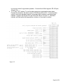
Refer to Figure 3-2 for connection of the followings items.
NOTE: All systems are shipped with a complete set of electrical schematics that depict
the “as built” version of the cabinet. Refer to these schematics along with this manual
when making connections.
Cooling Flow On/Off Relay Output
This feature provides a normally closed and open (form C) dry contact relay output to control
cooling flow.
Connect the cooling solenoid/chiller/contactor circuit to TB-100 pins 24 (NC), 25 (COM), 26
(NO) as required.
Cooling Flow Switch Interlock
This feature provides shutdown of the heater power in case of low or no cooling flow. This is
accomplished by opening the heater power controller contactor. The cooling sensor may be a
water flow or air flow switch. Use a switch with contact that are open during the fault condition.
Connect the flow switch to TB 100 pins 2 and 3. If both water and air cooling flow switches are
used in a system, wire the switches in series and then connect to the system.
Heater Over-Temperature Thermo-switch Interlock
This feature provides shutdown of the heater power in case of a heater over-temperature. This
is accomplished by opening the heater power controller contactor. If a thermo-switch is not
included with your heater, use a thermo-switch with contacts that will open during the overtemperature condition. If this feature is desired or provided with the heater, connect using the
following procedure:
• Remove the factory installed jumper at TB 100 pins 4 and 5.
• Connect the thermo-switch to TB 100 pins 4 and 5.
• If more than 1 thermostat is used, in a system, wire the switches in series and then
connect to the system.
Page 6 of 21