1
Temperature Control Option
This section contains temperature controller configuration information for your system. Refer to
the model XT19 installation and instruction manual for operating the temperature controller.
Setup Summary
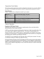
Table 4-1 displays factory configurations made for your system:
Sensor input (TCT
option)
Sensor input (TCP
option)
Control Type:
AL 1 (alarm 1):
Control output:
‘K’ type thermocouple scaled 0-2500 deg. F
4-20mA signal scaled 0-2500 deg. F
PID (proportional, integral, & derivative)
Full scale high, non-latching, set for 2000 deg. F (This alarm will trip
a relay connected to TB100 pins 13 and 14.)
0-20 milliamps
The alarm may be re-configured as necessary for your process
Theory of Operation
Principles of SCR Power Control
SCR type power controllers control power by regulating when silicon controlled rectifiers
(SCRs) conduct AC line current to the load.
A SCR is a solid-state, electronic switching device that turns on (fires) very quickly when a lowlevel “gating” signal is applied to its gate electrode. The timing of the gating signal, and
therefore the length of time the SCR conducts, is determined by the controller’s firing circuitry
in response to a control signal. The greater the percentage of time the SCR is on, the greater
the average power it allows to pass through to the load.
The Model 915 uses a random-fire solid state relay within its SCR poser controller. This relay
is a package consisting fo 2 SCRs and a gate drive circuit.
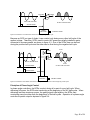
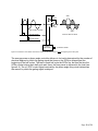
During the positive half-cycle of the AC line voltage the SCR’s anode is positive with respect to
its cathode, so during that half-cycle the SCR will begin to conduct whenever a gating signal is
applied to its gate electrode (see figure 4-2). Once turned on, an SCR will continue to conduct
until its anode-to-cathode voltage drops to zero, so the SCR continues to conduct until the end
of the half-cycle.
Page 11 of 21