1
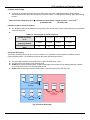
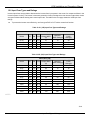
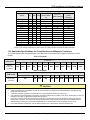
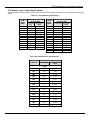
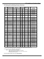
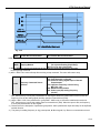
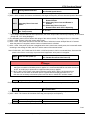
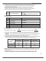
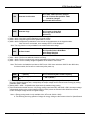
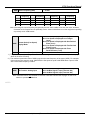
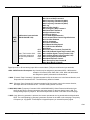
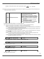
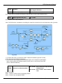
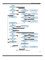
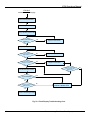
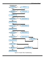
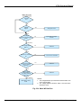
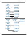
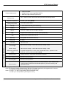
VCM Installation and Operations Manual 18.0 Control Mode Selection The VCM inverter series has three control modes: 1. General Vector Control. 2. VT (Variable torque) Vector Control (Special for Fans and Pumps). 3. V/f Control (Factory default). The user can select one of these control modes by following the flow chart below and setting the parameters as shown. When vector control is selected the motor HP must match the inverter rating. Select Control Mode Control Mode V/f Control A000=2 (Factory Default) Vector Control Parameters that can be Set: General Vector A000=0 B009 V/f Pattern A129 Torque boost A130 Motor no load current A131 Motor rated slip A132 Max. output frequency A133 Max. output voltage A134 Medium output frequency A135 Medium output voltage A136 Min. output frequency A137 Min. output voltage Suitable motor current A002 (OL1 reference) Variable Torque A000=1 Parameters to be Set: A001 Motor rated voltage A002 Motor rated current A003 Motor HP A004 Motor rated speed A005 Motor rated frequency A007 AC line input voltage Perform auto tuning : A006=1 END The V/f control mode should be used when the following conditions apply. (1) Using one inverter to drive several motors simultaneously. In this case the rated inverter output current must equal or exceed the sum total of all of the motors connected. The correct V/f pattern must be set by parameters A132 – A137. (2) The motors’ nameplate information is unknown or the motor ratings are not standard. In this case the inverter will set the motor characteristics in accordance with a standard MOTORTRONICS motor. (3) The specifications of the inverter and motor differ by more than 1 HP. In V/f control, A001 - A005 max. & min. values are determined by the MOTORTRONICS standard motor specification limit. When parameter A000 = 2 (V/f control), the keypad will display ‘Err2’ if Auto tuning is performed. Motortronics . Control Mode Selection 27