1
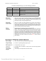
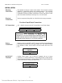
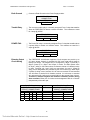
FIREFORCE 8
NOTIFICATION APPLIANCE CIRCUIT EXPANDER
INSTALLATION & OPERATION MANUAL
THE GAMEWELL COMPANY
60 PLEASANT STREET
ASHLAND, MA 01721
Technical Manuals Online! - http://www.tech-man.com
PN: 71981
ISSUE A
3/22/2001
FIREFORCE 8 Installation and Operation
Issue A 3/22/2001
This page intentionally blank
ii
Technical Manuals Online! - http://www.tech-man.com
FIREFORCE 8 Installation and Operation
Issue A 3/22/2001
PROPRIETARY MATERIAL
The information contained in this manual is proprietary to The Gamewell Company. Such information
and technical drawings may not be copied or reproduced in any manner, or disclosed to organizations
that might be competitive to Gamewell, without the express prior written consent of The Gamewell
Company.
iii
Technical Manuals Online! - http://www.tech-man.com
FIREFORCE 8 Installation and Operation
Issue A 3/22/2001
This page intentionally blank
iv
Technical Manuals Online! - http://www.tech-man.com
FIREFORCE 8 Installation and Operation
Issue A 3/22/2001
GENERAL INFORMATION
The Gamewell Company thanks you for choosing the FIREFORCE 8 Notification Appliance Circuit Extender.
As with all our products we have taken great care to insure that we have provided a quality product. To receive
maximum benefit and many years of reliable service we would like to make the following recommendations:
1. Read this manual carefully and in it's entirety before proceeding with the installation of the
FIREFORCE 8 panel.
2. Never make any connections with the power connected.
3. Gamewell spends many hours testing devices that are supplied by Gamewell to be used with it's
control panels to verify compatibility. To maximize system performance, and minimize risk of
damage to the equipment, we suggest using all Gamewell Components.
4. There is no substitute for proper maintenance and testing of this or any life safety product.
Gamewell recommends testing and maintenance of your FIREFORCE 8 in accordance with the
guidelines set forth by the National Fire Protection Association, to be done on a regular basis, as a
minimum.
5. This manual should be stored with the FIREFORCE 8 panel for future reference, and should
not be removed, providing reference to the operation and programming of the installed
FIREFORCE 8
Thank you again for choosing Gamewell. If you have any comments regarding your FIREFORCE 8 panel or
other Gamewell products, please contact us at:
The Gamewell Company
Product Marketing Department
60 Pleasant Street
Ashland, MA 01721
Tel. (508) 231-1400
Fax (508) 231-0900
v
Technical Manuals Online! - http://www.tech-man.com
FIREFORCE 8 Installation and Operation
Issue A 3/22/2001
This page intentionally blank
vi
Technical Manuals Online! - http://www.tech-man.com
FIREFORCE 8 Installation and Operation
Issue A 3/22/2001
Table of Contents
FIREFORCE 8 CIRCUIT NOTIFICATION APPLIANCE EXPANDER ............................................................. 9
General Description ............................................................................................................................................. 11
FUNCTIONAL DESCRIPTION ............................................................................................................................. 12
Normal Quiescent Operation .............................................................................................................................. 12
Alarm Condition .................................................................................................................................................... 12
Reset ...................................................................................................................................................................... 12
Trouble Condition ................................................................................................................................................. 12
Normal AC ............................................................................................................................................................. 13
Power Failure ........................................................................................................................................................ 13
Delayed AC Power Failure.................................................................................................................................. 13
Battery Operation ................................................................................................................................................. 13
ELECTRICAL OPERATING CHARACTERISTICS .......................................................................................... 13
Input Voltage ......................................................................................................................................................... 13
Output Voltage ...................................................................................................................................................... 13
INSTALLATION ...................................................................................................................................................... 14
Mounting Instructions ........................................................................................................................................... 14
Electrical Connections ......................................................................................................................................... 14
FUNCTION OF INPUT/OUTPUT CONNECTIONS ............................................................................................................... 14
AC Connections.................................................................................................................................................... 14
Battery Connections............................................................................................................................................. 14
24 VDC OUT Terminals....................................................................................................................................... 14
Earth Ground......................................................................................................................................................... 15
Trouble Relay........................................................................................................................................................ 15
POWER FAIL ........................................................................................................................................................ 15
Extender Output Circuit Wiring ........................................................................................................................... 15
Reference EOL Resistor...................................................................................................................................... 16
Input signal wiring................................................................................................................................................. 16
FUNCTION OF SWITCHES, DIODES AND JUMPERS ......................................................................................................... 16
PROGRAMMING SWITCHES ........................................................................................................................................... 16
Outputs 1 & 2 .......................................................................................................................................................... 16
Outputs 3 & 4 .......................................................................................................................................................... 17
Sync. Codes ............................................................................................................................................................. 17
Power Fail Reporting.............................................................................................................................................. 17
Input Select ............................................................................................................................................................. 17
FUNCTION OF INDICATORS ........................................................................................................................................... 17
OPERATION ............................................................................................................................................................ 18
START-UP PROCEDURE ................................................................................................................................................ 18
OPERATING INSTRUCTIONS .......................................................................................................................................... 18
Alarm Condition .................................................................................................................................................... 18
Trouble Condition ................................................................................................................................................. 18
Testing and Maintenance .................................................................................................................................... 18
BATTERY APPLICATIONS .............................................................................................................................................. 18
Battery Capacity ................................................................................................................................................... 18
APPENDIX A............................................................................................................................................................. 19
COMPATIBLE NOTIFICATION DEVICES .......................................................................................................................... 21
vii
Technical Manuals Online! - http://www.tech-man.com
FIREFORCE 8 Installation and Operation
Issue A 3/22/2001
APPENDIX B .............................................................................................................................................................23
DRAWINGS ...................................................................................................................................................................25
FireForce 8 Battery Calculation Chart................................................................................................................26
viii
Technical Manuals Online! - http://www.tech-man.com
FIREFORCE 8 CIRCUIT NOTIFICATION
APPLIANCE EXPANDER
Technical Manuals Online! - http://www.tech-man.com
FIREFORCE 8 Installation and Operation
Issue A 3/22/2001
This page intentionally blank
10
Technical Manuals Online! - http://www.tech-man.com
FIREFORCE 8 Installation and Operation
Issue A 3/22/2001
INTRODUCTION
General
Description
The FIREFORCE 8 is a notification appliance circuit extender panel designed
to extend the power capabilities of existing notification appliance circuits and
provide power for other ancillary devices.
An FIREFORCE 8 panel consists of two notification appliance circuit inputs
and four class B, style Y or two class A, style Z, notification appliance circuits.
st
Two class B (1 class A) circuits will always be controlled by the 1 input, the
other two class B (1 class A) circuits may be operated from either input. Each
of these output circuits are capable of providing 2.5 amps of power limited
notification appliance power and are supplied from an 8 Amp regulated 24
VDC power supply. Outputs may follow the inputs, or be programmed to
provide temporal outputs for a steady input They can also be programmed to
provide strobe and horn synchronizing signals when none are on the input.
The internal sync. signals can permit horns and strobes to be connected to a
single wire pair on each output, controlled by the two inputs, or they can be
separated and operated on individual outputs. All inputs and outputs are
supervised for open or shorted conditions. EOL resistor values can be
changed by connecting a sample EOL resistor to the unit. This allows
compatibility with existing NAC circuits. An internal battery charger is also
provided with the FIREFORCE 8 to provide standby battery operation. The
panel is mounted in a rigid sheet metal enclosure with the dimensions of (12
5/8"W x 18"H x 4 1/2"D ).
11
Technical Manuals Online! - http://www.tech-man.com
FIREFORCE 8 Installation and Operation
Issue A 3/22/2001
FUNCTIONAL DESCRIPTION
Normal
Quiescent
Operation
In the normal quiescent condition the green Power On LED is illuminated
indicating AC line operation. The yellow TRBL LED s are off indicating that all
supervision circuits are normal.
Alarm Condition
Whenever an alarm condition occurs at the Main FACP the resultant 24V
output from it’s indicating circuit will energize the connected polarity sensing
inputs. This input will then activate the notification appliance output circuits on
the FIREFORCE 8 according to how they are programmed. Input 1 will always
control Outputs 1 and 2. Input 2 normally controls Outputs 2, and 3 (Default)
however this pair of outputs can be programmed to operate from Input 1. The
FIREFORCE 8 notification appliance circuits will follow steady, march time,
temporal or coded signals from the main control panel, and will pass on strobe
and horn synchronization signals if they are present on the input.
When the unit is programmed to generate synchronization signals, combined
horn and strobe synch. signals are placed on each selected output pair and
turned on and off by the inputs in the manner described as default above.
When the unit is programmed to generate synchronization signals and have
all four outputs controlled by input 1, the strobe synch. signals are placed on
all four outputs when input 1 is active. When input 1 and 2 are active, the horn
synch. signals are combined with the strobe synch. signals on all four outputs.
In this manner, horns and strobes can be connected to same pair of wires on
any output, and be controlled individually
Reset
The FIREFORCE 8 will return to the quiescent condition automatically upon
restoration of the Main FACP to normal operation
Trouble
Condition
A trouble condition is indicated by a TRBL LED illuminating and the common
Form "C" TROUBLE FAIL relay contacts transferring. The trouble signal will
be transmitted to the Main FACPs by opening the Indicating Circuits which are
used to control the FIREFORCE 8. An alarm from the main control panel will
override a trouble condition.
The FIREFORCE 8 monitors it’s output notification appliance circuits for an
open or shorted condition. Notification appliance circuits with a short circuit
trouble can not be activated.
12
Technical Manuals Online! - http://www.tech-man.com
FIREFORCE 8 Installation and Operation
Issue A 3/22/2001
A trouble is indicated by any one of the following conditions:
INDICATOR
NAME
LED 8
LED 7
PWR ON
AUX TRBL
LED 6
LED 5
LED 4,3,2,1
BATT TRBL
GF TRBL
SIG(4,3,2,1) TRBL
TROUBLE CONDITION
-a brown-out or black-out AC line condition
A low or missing output, or a short circuit on the
AUXilliary output
-a low or missing battery
-an earth fault on external wiring
-a short circuit or an open on a supervised notification
appliance circuit
Normal AC
Power Failure
When the AC fails or falls below 95VAC (Brown out), the FIREFORCE 8 will
go into the Trouble condition. It will switch to Battery Operation, deactivate the
Trouble and Power Fail relays, extinguish the AC On LED (LED 8), and
transmit the trouble over the input Signal Circuits.
Delayed AC
Power Failure
When S7 AC 6HR is set (Dialer Operation) An AC failure will be handled in
the same manner as above EXCEPT the TROUBLE relay will not transfer,
and the failure notification will not be transmitted over the input Signal Circuits
until the failure has existed for 6 hours. The POWER FAIL relay will transfer in
order to provide an external trouble indication.
Battery
Operation
Indicated by the extinguishing of the green Power On LED.
Standby operation occurs whenever the main power source fails or falls below
95VAC. In this situation the FIREFORCE 8 will automatically transfer system
operation to the standby battery set without the loss of any alarm condition
present prior to the transfer. The FIREFORCE 8 panel will transfer back to the
main power source when the operating voltage returns to 105VAC. Should the
battery become disconnected, have a blown fuse, or develop low voltage, the
FIREFORCE 8 will indicate a Battery fault and light LED 2. Replace batteries
when required.
ELECTRICAL OPERATING CHARACTERISTICS
Input Voltage
120 to 240 VAC (Jumper selected)50/60 Hz @ 5 Amps.
Output Voltage
24 Volt DC regulated @ 8Amps-system power.
NAC outputs 1-4
2.5 Amps Maximum per output.
AUX Power
0.15 Amps under all conditions. 2 Amps if load is removed during operation
from battery.
Total loading on all outputs shall not exceed 8 Amps.
Total System
Current
13
Technical Manuals Online! - http://www.tech-man.com
FIREFORCE 8 Installation and Operation
Issue A 3/22/2001
INSTALLATION
Mounting
Instructions
The standard mounting is a surface mount cabinet. The unit must be securely
attached to a permanent partition using suitable fasteners. Four mounting
holes are provided to accept 1/4 inch dia. screws max. There are nine
combination knockouts provided, located three on the top and three on each
side of the cabinet. Knockouts can accept 1/2, or 3/4 inch conduit.
Electrical
Connections
See Inter-equipment Wiring DWG. No. B-W479 for field wiring connections.
Function of Input/Output Connections
AC Connections
120 – 240VAC connects to the AC Terminal Block on the Power Supply
CONNECTIONS FOR THE A.C MAINS
J1 TERMINALS
L1 (Hot)
GND
L2 (Neutral)
WARNING!
WHEN INSTALLING TO OPERATE FROM
200VAC-240VAC IT IS NECESSARY TO REMOVE THE
JUMPER E1-E2 ON THE POWER SUPPLY PRINTED CIRCUIT
BOARD. FAILURE TO DO SO WILL RESULT IN DAMAGE TO
THE POWER SUPPLY WHEN AC VOLTAGE IS APPLIED.
Battery
Connections
Batteries connect to the BATT+, BATT- terminals. Sealed Lead Acid Batteries
are required to provide 24 Volts DC @ 8 Amps max., The maximum battery
size allowable is 24AH. Connect ONLY with the provided cable and a 15A
fuse.
CONNECTIONS FOR THE
BATTERY
TB1 TERMINALS
BATT +
BATT -
24 VDC OUT
Terminals
Auxiliary Power Output @ 24 Volts DC, regulated 150 mA, (2 Amps
maximum if an external disconnect is used during periods of power failure).
Two terminals are provided (+,-). Power limited output of 2 amps. (Deduct the
current used from the 8 Amps total system load)
CONNECTIONS FOR
AUXILIARY 24 VDC
TB4 TERMINALS
A+
A-
14
Technical Manuals Online! - http://www.tech-man.com
FIREFORCE 8 Installation and Operation
Earth Ground
Issue A 3/22/2001
Connect to Earth Ground on the Power Supply module.
EARTH GROUND
CONNECTION
J1 TERMINAL
GND
Trouble Relay
The common trouble relay is a normally energized Form C relay that transfers
when the FIREFORCE 8 detects a trouble condition. The contacts are rated
for 2 amps @ 30VDC.
TROUBLE FAIL
TB2 TERMINALS
NC
COMM
NO
POWER FAIL
The Power Fail relay is a normally energized Form C relay that transfers when
a power failure or brown out condition exists. The contacts are rated for 2
amps @ 30VDC.
POWER FAIL
TB2 TERMINALS
NC
COMM
NO
Extender Output
Circuit Wiring
The FIREFORCE 8 Notification Appliance Circuit outputs can provide up to
2.5 Amps (power limited) of regulated 24 VDC each (total panel output is
limited to 8 Amps). The outputs can be arranged as 4 Style Y (Class B), 2
Style Z (Class A) or 1 Style Z and 2 Style Y circuits. The EOL resistor value
for Style Y wiring is 3.9K ohms unless a reference resistor of a different value
is used. Terminals (n)L1 and (n)L2 are connections for style Y (Class B)
wiring These designations are preceded by the circuit number (n). When Style
Z (Class A) wiring is used, terminal 1L1 will return to terminal 2L1 and terminal
1L2 will return to terminal 2L2, likewise, terminal 3L1 will return to terminal
4L1 and terminal 3L2 will return to terminal 4L2 for the second Class A circuit.
Terminal L1 switches negative and terminal L2 switches positive during
alarm condition. Either pair of circuits can be designated Class A or Class B
independently of the other pair.
Style Z - Class A
NOTIFICATION APPLIANCE
CIRCUIT CONNECTIONS
TERMINALS
1L1
2L1
1L2
2L2
3L1
4L1
3L2
4L2
-
Circuit
1
2
3
4
15
Technical Manuals Online! - http://www.tech-man.com
Style Y - Class B
NOTIFICATION APPLIANCE
CIRCUIT CONNECTIONS
TERMINALS
1L1
1L2
2L1
2L2
3L1
3L2
4L1
4L2
FIREFORCE 8 Installation and Operation
Reference EOL
Resistor
Issue A 3/22/2001
To accommodate existing Notification Appliance circuits that have EOL
resistors of values different from the 3.9K ohm normally used with the NAC
outputs of this panel, provisions are made to attach a reference EOL resistor
within the range of 2.0K to 25.0K ohms. When the reference resistor is used,,
all Style Y (Class b) outputs must have EOL resistors of the same value as
the reference resistor. EOL values outside of the 2.0K – 25.0 K range will
cause all of the Style Y NAC output Trouble LEDs to light steady.
REF
TB3 TERMINALS
REF+
REF-
Input signal
wiring
The main FACP notification appliance circuit inputs are +IN, -IN. When
polarity is reversed on the main FACP notification appliance circuit, the output
circuits on the FIREFORCE 8 will activate according to their programming.
These inputs restore when the Main FACP circuit is restored. +IN and -IN are
internally connected to +OUT and -OUT for connection to devices beyond the
FIREFORCE 8. Should a trouble condition occur, the circuit is opened. If an
alarm is received during trouble the circuit is restored to allow devices beyond
the FIREFORCE 8 to be operated. Signal 1 always activates output Signal
Circuits 1 and 2., and depending on the position of switch SW1-8 can also
control output Signal Circuits 3 and 4. Otherwise, Signal 2 controls output
Signal Circuits 3 and 4.
1+IN
SIGNAL 1
TERMINALS
1-IN
1+OUT
2+IN
SIGNAL 2
TERMINALS
2-IN 2+OUT
1-OUT
2-OUT
Function of Switches, Diodes and Jumpers
Programming Switches
Outputs 1 & 2
SW-1 1
SIG1/2A
Open
Closed
Open
Closed
SW-1 2
SIG1/2B
Open
Open
Close
Closed
Function
Output follows the Input
Steady Input, Temporal Output
Steady Input, Steady Output, Strobe Sync. added
Steady input, steady output, noise eliminated.
16
Technical Manuals Online! - http://www.tech-man.com
FIREFORCE 8 Installation and Operation
Issue A 3/22/2001
Outputs 3 & 4
SW-1 3
SIG3/4A
Open
Closed
Open
Closed
SW-1 4
SIG3/4
Open
Open
Close
Closed
Function
Output follows the Input
Steady Input, Temporal Output
Steady Input, Steady Output, Strobe Sync. added
Steady input, steady output, noise eliminated.
Sync. Codes
SW-1 5
SYN/SELA
Open
Closed
Open
Closed
SW-1 6
SYN/SELB
Open
Open
Close
Closed
Function
Wheelock Sync
System Sensor Sync
Faraday Sync
Reserved
Power Fail
Reporting
SW-1 7
AC 6HR
Open
Closed
Function
TROUBLE FAIL reported immediately on power failure
TROUBLE FAIL delayed for 6 hours on power failure
Input Select
SW-1 8
SIG SEL
Closed
Open
Function
Outputs 3 / 4 controlled by Input 2
Outputs 3 / 4 controlled by Input 1, also in generate
synchronization mode, Input 1 controls strobe synch. signals
and, Input 2 controls horn synch. signals, both of which are
combined on all 4 outputs.
Function of Indicators
INDICATOR
PWR ON
LED #
LED # 8
COLOR
Green
AUX TRBL
BATT TRBL
LED # 7
LED # 6
Yellow
Yellow
GF TRBL
LED # 5
Yellow
Notification
appliance Circuit 1
Notification
appliance Circuit 2
Notification
appliance Circuit 3
Notification
appliance Circuit 4
LED # 4
Yellow
LED # 3
Yellow
LED # 2
Yellow
LED # 1
Yellow
DESCRIPTION
Indicates AC line operation.
Indicates a short or overloadon the Aux. Output.
Indicates a low battery voltage or missing
battery.
Indicates an external wiring connection is not
adequately isolated from the earth ground.
Indicates a short or open circuit in the external
wiring..
Indicates a short or open circuit in the external
wiring.
Indicates a short or open circuit in the external
wiring.
Indicates a short or open circuit in the external
wiring.
17
Technical Manuals Online! - http://www.tech-man.com
FIREFORCE 8 Installation and Operation
Issue A 3/22/2001
OPERATION
Start-up Procedure
Connect A.C. first, then connect batteries
Operating Instructions
Alarm Condition
Alarm devices operate in unison with the Main FACP alarm devices. The
alarm activated outputs are reset through operation of the Reset switch on the
Main FACP.
Trouble
Condition
The associated trouble LED ( yellow ) will illuminate.
Testing and
Maintenance
System Testing should be performed periodically to insure proper operation.
1. Test the indicating circuits by initiating an alarm or test at the Main
FACP.
2. Test for proper operation by actuating the notification appliance circuit
the FIREFORCE 8 is monitoring.
3. Standby batteries and AC transfer are tested by interrupting the AC
power line while an alarm test condition exists (see 1 above).
Battery Applications
Battery Capacity
Battery Capacities is 24 ampere-hours maximum for the FIREFORCE 8. The
max. charging rate is . 75 amps.
18
Technical Manuals Online! - http://www.tech-man.com
FIREFORCE 8 Installation and Operation
Issue A 3/22/2001
Appendix A
Compatible
Notification
Devices
19
Technical Manuals Online! - http://www.tech-man.com
FIREFORCE 8 Installation and Operation
Issue A 3/22/2001
This page intentionally blank
20
Technical Manuals Online! - http://www.tech-man.com
FIREFORCE 8 Installation and Operation
Issue A 3/22/2001
Compatible Gamewell Notification Devices
Part #
Catalog #
Part #
Catalog #
Part #
Catalog #
70871
70873
71138
71140
71287
71288
71289
71290
71292
71293
71294
71295
71426
71427
71543
71544
71545
71546
71547
71548
71549
71550
71551
71552
71553
71554
71555
71556
71557
71558
71559
71560
71561
MIZ-24-R
MIZ-24-W
MT-12/24-R
MT-24-WM-VFR
MIZ-24-LS-VFR
MIZ-24-LSM-VFR
MIZ-24-MS-VFR
MIZ-24-IS-VFR
MT-24 -LS-VFR
MT-24-LSM-VFR
MT-24-MS-VFR
MT-24-IS-VFR
MT-24 -SL-VFR
MT-24-SLM-VFR
AS-2415-VFR
AS-241575-VFR
AS-2430-VFR
AS-2475-VFR
AS-24110-HFR
SM-12/24-R
DSM-12/24-R
RS-2415-VFR
SR-2415-VFR
SRP-2415-VFR
RS-241575-VFR
SRP-241575-VFR
SR-241575-VFR
RS-2430-VFR
RSP-2430-VFR
RSP-2475-VFR
RS-2475-VFR
RS-24110-HFR
SRP-24110-HFR
71562
71569
71573
71574
71575
71576
71614
71616
71679
71680
71681
71682
71683
71684
71685
71686
71687
71688
71689
71690
71691
71692
71693
71694
71695
71696
71697
71698
71699
71711
71712
71713
71714
SR-24110-HFR
RSP-241575-VFR
AMT-12/24-R
AMT-24-LS-VFR
AMT-24-IS-VFR
AMT-24-LSM-VFR
MT4-12/24-R
SR-2475-VFR
AS-2415W-FR
AS-241575W-FR
AS-2430W-FR
AS-2475W-FR
AS-24110W-FR
AS-24100C-FW
NH-12/24-R
NS-2415W-FR
NS-241575W-FR
NS-2430W-FR
NS-2475W-FR
NS-24110W-FR
RSS-2415W-FR
RSS-241575W-FR
RSSP-241575W-FR
RSSP-2430W-FR
RSS-2430W-FR
RSSP-2475W-FR
RSS-2475W-FR
RSS-24110W-FR
RSS-24100C-FW
AH-24WP-R
RS-2415W-FR
RS-241575W-FR
W3MT-24-VFR
71717
71727
71728
71729
71730
71731
71732
71733
71736
71737
71738
71739
71740
71741
71742
71743
71744
71745
71746
71747
71748
71749
71750
71751
71752
71758
71759
71760
71761
71762
71763
71764
RSSP-24110W-FR
AS-2415C-FW
AS-2430C-FW
AS-2475C-FW
RSS-2415C-FW
RSS-2430C-FW
RSS-2475C-FW
RSSP-2415W-FR
ET70-2415W-FR
ET70-241575W-FR
ET70-2430W-FR
ET70-2475W-FR
ET90-2415C-FW
ET90-2430C-FW
ET90-2475C-FW
ET90-24100C-FW
E70-2415W-FR
E70-241575W-FR
E70-2430W-FR
E70-2475W-FR
E70-24110W-FR
E90-2415C-FW
E90-2430C-FW
E90-2475C-FW
E90-24100C-FW
CH90-24-W
CH70-24-R
CH70-2415W-FR
CH70-241575W-FR
CH70-2430W-FR
CH70-2475W-FR
CH70-24110W-FR
21
Technical Manuals Online! - http://www.tech-man.com
FIREFORCE 8 Installation and Operation
Issue A 3/22/2001
Synchronized Horns and Strobes
System Sensor
SC2415_
SC241575_
SC2430_
SC2475_
SC2495_
SC24115_
SC24177_
PC2415_
PC241575_
PC2430_
PC2475_
PC2495_
PC24115_
PC24177_
Faraday
2700 Sync Series
22
Technical Manuals Online! - http://www.tech-man.com
Wheelock
AS-24MCW
RSS-24MCW
Appendix B
Drawings
Technical Manuals Online! - http://www.tech-man.com
FIREFORCE 8 Installation and Operation
Issue A 3/22/2001
THIS PAGE INTENTIONALLY BLANK
24
Technical Manuals Online! - http://www.tech-man.com
FIREFORCE 8 Installation and Operation
Issue A 3/22/2001
Drawings
Battery Calculation Chart
B-W479
Wiring, Notification Appliance Circuit Expander
25
Technical Manuals Online! - http://www.tech-man.com
FIREFORCE 8 Installation and Operation
Issue A 3/22/2001
FireForce 8 Battery Calculation Chart
Circuit
Notification Appliance Ckt. 1
Normal Current
Alarm Current
Cl A, 050A + Device Load 1 or
Cl B, 065A + Device Load 1 & 2
Notification Appliance Ckt. 2
Notification Appliance Ckt. 3
Cl A, 050A + Device Load 3 or
Cl B, 065A + Device Load 3 & 4
Notification Appliance Ckt. 4
External Load A+, A+/- 24 VDC
Common Control
.030 A
.055 A
Normal Current
(Total of Center Column)
Alarm Current
(Total of Right Column)
HOURS OF
STANDBY
TOTAL
NORMAL
CURRENT
x
HOURS OF
ALARM
=NORMAL Amp Hours
TOTAL
ALARM
CURRENT
x
=ALARM Amp Hours
TOTAL Amp Hours
X 1.25
Safety Factor
BATTERY AH REQUIRED
24 AH Max
NOTE:
Normal current times total number of standby hours = Total Normal Current
Alarm current times total number hours of alarm = Total Alarm Current
Total normal current + Total alarm current + 25% = Minimum Battery Size
Total Load Of Notification Appliance Ckt. And External Load Not To Exceed 8 Amps.
26
Technical Manuals Online! - http://www.tech-man.com
FIREFORCE 8 Installation and Operation
Issue A 3/22/2001
27
Technical Manuals Online! - http://www.tech-man.com