1
TIDLAND WINDING SOLUTIONS
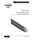
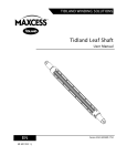
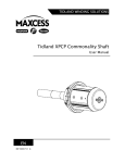
Tidland G690 Leaf Shaft
Operation and Maintenance
EN
MI 746510 1 C
3" Shaft Diameter
CONTENTS
INTRODUCTION
1-1
About these operating instructions ...................................................................... 1-1
Product overview .................................................................................................. 1-2
Model number key ............................................................................................... 1-2
SAFETY INFORMATION
2-1
Proper use ............................................................................................................ 2-2
Decommissioning................................................................................................. 2-3
ASSEMBLY DIAGRAM AND PARTS LIST
3-1
Shaft components ................................................................................................ 3-1
Parts List .............................................................................................................. 3-2
OPERATION
4-1
Air pressure ......................................................................................................... 4-1
MAINTENANCE
5-1
Recommended tools and supplies ........................................................................ 5-1
Maintenance schedule .......................................................................................... 5-1
Removing a journal .............................................................................................. 5-2
Air system ............................................................................................................ 5-4
Replacing a bladder ......................................................................................... 5-4
Using bulk bladder material............................................................................. 5-5
Valve, o-rings, and air hose............................................................................. 5-9
TROUBLESHOOTING
6-1
SPECIFICATIONS
7-1
SERVICE AND PARTS
8-1
www.maxcessintl.com
Tidland G690
MI 746510 1 C
1-1
INTRODUCTION
About these operating
instructions
All of the information herein is the exclusive proprietary
property of Maxcess International, and is disclosed with the
understanding that it will be retained in confidence and will
neither be duplicated nor copied in whole or in part nor be
used for any purpose other than for which disclosed.
Copyright 2012, all rights reserved.
Periodically there will be updates to this manual. The latest
version is available at www.maxcessintl.com or by calling
your regional office listed on the back page of this
publication.
These instructions are designed to help put the external
element winding shafts into service and provide important
notes for the proper use of the shaft. These instructions are
valid for following shaft series:
Series G690C
These instructions are important for the machine
manufacturer, end user, machine operator and maintenance
personnel. Read and understand these instructions before
installing and operating the shaft.
The instructions must be read and used by all persons who
have the responsibility of installing and maintaining these
shafts.
These instructions must be retained and incorporated in the
technical documentation for the machine or partly completed
machinery into which the shaft is installed.
The start-up of this winding shaft is forbidden until it is
determined that the control, which the operator understands,
and the machine into which it has to be assembled,
correspond with the regulations of the applicable ECguidelines.
These are the original instructions, written in English.
www.maxcessintl.com
Tidland G690
MI 746510 1 C
1-2
INTRODUCTION
Theory of operation
The Tidland G690 is a narrow to medium web width core shaft
with an aluminum body and leaves. External bladders activate
four expanding leaves that grip the core. The bladders are
ultrasonically sealed and secured with screw clamps. Air is
delivered to the shaft through a valve located in the end or on
the side of the shaft body, or through a rotary union.
Model number key
Shaft series – shaft type – mounting style
Shaft series
G – Global
Shaft type
690 = External element leaf shaft
Mounting
None = drop-in
type
C = cantilevered
Available models
G690
G690C
www.maxcessintl.com
Tidland G690
MI 746510 1 C
2-1
SAFETY INSTRUCTIONS
Safety Information
When using this Tidland product, always follow basic safety
precautions to reduce the risk of personal injury. Your
company's safety instructions and procedures should always
be followed. When using this product with any other
equipment or machinery, all safety requirements stipulated by
that equipment or machinery manufacturer must be followed.
Compliance with local, state, and federal safety requirements
is your responsibility. No part of these or the following
instructions should be construed as conflicting with or
nullifying the instructions from other sources. Be familiar with
the hazards and safety requirements in your work
environment and always work safely.
Read and understand all instructions and shaft design
application limits before operation.
–
Never use this product for a purpose or in a machine that it
was not specifically designed for. See Product Safety Data
Sheet (PSDS).
–
Do not exceed the operation loads for this shaft as noted
on its PSDS, Product Safety Data Sheet.
–
Follow all warnings and instructions marked on the product
and on the PSDS.
–
Do not use fingers or other objects to deflate the shaft; use
only the Tidland deflation tool.
–
Inspect the shaft for wear and/or other safety and
functional deficiencies daily, before each use.
–
Wear safety glasses or proper eye protection when inflating
or deflating or otherwise operating the air system.
–
Do not remove or otherwise alter any setscrews or
fastening devices prior to using this product.
–
Do not operate this product if any setscrews or fastening
devices are missing.
–
Do not lift shaft manually if it is beyond your capacity.
Loads over 1/3 your body weight may be prohibitive.
Consult your company safety policy.
–
When lifting a shaft, use proper lifting techniques, keeping
back straight and lifting with the legs.
(continued)
www.maxcessintl.com
Tidland G690
MI 746510 1 C
2-2
SAFETY INSTRUCTIONS
–
Do not carry or lift this product over wet or slippery
surfaces.
–
Use appropriate mechanical lifting devices, such as a hoist
or shaft puller, for heavier shafts.
–
When performing maintenance or repair procedures, do
not pressurize the shaft if journal setscrews are loose or
missing.
–
When performing maintenance procedures, do not
pressurize the shaft if the journal is missing.
–
All replacement parts used on this product should be made
to original Tidland specifications.
–
All maintenance and repair procedures performed on this
product should be done to Tidland specifications by
qualified personnel.
Basic safety information
To ensure safe and problem-free installation of the winding
shaft, the shaft must be properly transported and stored,
professionally installed and placed in operation. Proper
operation and maintenance will ensure a long service life of
the shaft. Only persons who are acquainted with the
installation, commissioning, operation and maintenance of
the system and who possess the necessary qualifications for
their activities may work on the shaft
Proper use
–
The Tidland G690 shaft is intended to be used on unwind
or rewind machines.
Improper use
–
Operation outside the technical specifications
–
Any other use than the proper use shall be deemed
inappropriate.
www.maxcessintl.com
Tidland G690
MI 746510 1 C
2-3
SAFETY INSTRUCTIONS
Basic safety
information
(continued)
Installation and commissioning
WARNING – Danger of falling down or muscle or skeletal
injury during installation
The larger design shafts are heavy. Appropriate equipment is
to be used and the safety rules of the company must be
observed.
Operation
WARNING – Danger of entanglement or pinching during
operation
Keep hands and loose clothing away from rotating shaft.
Maintenance and repair
WARNING - Danger of entanglement or pinching
Maintenance and repair tasks on the shaft must be performed
only when the machine has been stopped and has been
secured from being turned on again.
WARNING – Danger of bodily injury or damage to hearing.
Do not inflate bladders without the leaves installed.
Decommissioning
The shaft must be disposed of in accordance with all the
applicable national, state and local regulations.
www.maxcessintl.com
Tidland G690
MI 746510 1 C
3-1
ASSEMBLY DIAGRAM AND PARTS LIST
Shaft components
Drop-in
Cantilever
Free end
Fixed end
www.maxcessintl.com
Tidland G690
MI 746510 1 C
3-2
ASSEMBLY DIAGRAM AND PARTS LIST
a/r = as required
Parts List
* Recommended spare parts
Part No.
Part No.
Item
Description
Qty
(N. Amer.)
(Europe)
1
Soc hd cpscr
4
752636
M259472
2
Nose cone
1
742523
M366382
3
Flat hd cpscr M3 x 16 mm
4
250039
n/a
4
End cover for side valve (drop-in)
1
759417
M369270
5
Journal
1
Custom
Custom
*
6
O-ring, Parker
2
746599
M369268
*
7
Air fitting barb (supplied with gasket)
2
748908
M371134
*
8
Coiled air hose
a/r
748907
M371133
*
9
Bladder
a/r
739338
M193425
*
10
Air fitting
4
739339
M250318
*
11
Protection strip
a/r
739340
M245285
*
12
End clamp, bottom
8
740602
M237218
*
13
End clamp, top
8
741758
M365794
14
Set screw, end clamp M4 x 6 mm
16
739345
M141619
15
Leaf
a/r
740912
M740912
*
16
Wave spring
a/r
617952
M322356
*
17
Valve, G1/8 (supplied with gasket)***
1
739343
M266978
18
Soc hd cpscr M5 x 20 mm, Class 8.8, zinc plated
19
Bushing (4 per journal)
20
Core stop, optional
21
Journal with shoulder
22
End cover (drop-in)
23
Nose cone
24
Soc hd cpscr M3 x 20 mm, Class 8.8, zinc plated
25
OBSOLETE
†
4
544155
n/a
a/r
746694
M269271
1
564239
M367400
a/r
Custom
Custom
††
1
759416
M369269
OBSOLETE:
1
743718
M365790
4
752636
M259472
Nose cone (cantilever)
1
741797
M365790
26
Plug, OBSOLETE ****
1
747517
M370040
27
Air transfer plug
1
747516
M370038
28
Body cover, inboard
1
741775
M365789
29
Flat hd cpscr M3 x 16 mm
2
250039
n/a
1
Custom
Custom
Optional
Calibration tape
*** Valve gasket is available separately (745181) (M284758)
**** Obsolete March 2013: replace with item 27. If not using end valve, also order plug 128045 (M186986).
†
On shaft serial numbers prior to 761476, part number was 746301.
††
On shaft serial numbers prior to 761476, part number was 746290.
www.maxcessintl.com
Tidland G690
MI 746510 1 C
4-1
OPERATION
Operation
Air pressure
Use only clean, dry, non-lubricated air.
Shaft operation requires 5.5-8.3 bar [80-120 psi].
Connect air hose to the air supply. When inflating shafts not
equipped with a rotary union, Tidland recommends the use of a
Tidland Inflation Tool. See page 5-1.
Preparing the shaft
for operation
Do not rotate shaft without a core installed on expansion
elements.
1. Position the shaft in the core.
2. Ensure that all expansion elements are covered by cores or
rolls.
Inflating the shaft
Use the Tidland Inflation Tool to inflate the shaft. Hold the nozzle
in place until the line pressure air gauge indicates 5.5-8.3 bar
[80-120 psi].
Deflating the shaft
Use an appropriate tool to release air from the shaft.
Do not use your finger to deflate the shaft.
The Tidland Air Release Tool is available on request.
See page 5-1 for part number.
www.maxcessintl.com
Tidland G690
MI 746510 1 C
5-1
MAINTENANCE
Recommended
tools and supplies
Hex drive wrenches: 2, 2.5, 4 mm
Tidland inflation tools (contact Maxcess for options)
Tidland air release tool (Tidland 111630)
Tidland valve removal tool:
Tidland North America
745083 (wrench)
749067 (tool bit only)*
Maxcess Europe
M296213 (wrench)
M373530 (tool bit only)*
Dow Corning Molykote® 55 o-ring grease
Loctite® 222 (or equivalent)
Loctite® 243 (or equivalent)
Hole punch guide (Tidland Part No. 760792)
Hole punch tool (Tidland Part No. 760668)
* This part is a tool bit for use with a torque wrench.
Using Loctite or
equivalent thread locker
Always use a thread locker on component threads during
reassembly.
Component
Threadlocker
Element end clamp fasteners
Air fitting barbs
Loctite® 222
Valves
Journal or end cap fasteners
Maintenance
schedule
Loctite® 243
Daily
Keep shaft clean and dry.
Remove dust and debris buildup with compressed air.
Periodically
Inspect journals for wear.
Check for worn or damaged expansion elements.
www.maxcessintl.com
Tidland G690
MI 746510 1 C
5-2
MAINTENANCE
Removing a journal
To avoid damage to the shaft, Tidland recommends that you
remove all of the external elements and bladders, and then
secure the shaft in a round clamping fixture before removing
the journal.
1. If there is a side valve installed, remove it from the shaft.
In some cases, you will need to remove the end valve to
install a journal removal tool.
2. Remove four M5 socket head cap screws and bushings.
3. Use impact puller to remove the journal.
.
www.maxcessintl.com
1
M5 Soc hd cap screw
2
Bushing
3
Shaft body
4
Journal
Tidland G690
MI 746510 1 C
5-3
Reinstalling the
MAINTENANCE
4.
journal
1. Reconnect the hose to the fitting on the journal.
2. Apply o-ring grease to the fit area.
3. Torque the M3 socket head cap screws to 5 Nm [44 in·lbs].
4. Remove the shaft body from the clamping fixture; reinstall
the external elements and bladders. See page 5-6.
www.maxcessintl.com
Tidland G690
MI 746510 1 C
5-4
MAINTENANCE
Air system
Replacing a bladder
1. Remove four M3 screws and end cover.
2. Loosen – do not remove – the M4 set screws in both end
clamps.
3. Remove clamps and expansion elements from shaft.
1
M3 Soc hd cap screw
2
End cover / journal feature
3
End clamp assembly
4
Leaf
5
Sealed bladder assembly
6
Protection strip material
(continued)
www.maxcessintl.com
Tidland G690
MI 746510 1 C
5-5
MAINTENANCE
Cutting the new
bladder
Using bulk bladder material
If you use bulk bladder material instead of the sealed bladder
assembly, use the following formula to determine the correct
replacement bladder length for your shaft.
bladder length = leaf length + 60 mm [2.36"]
* Punch through one wall only
(2)
(1)
(3)
1
Hole locater guide
2
Tidland hole punch
3
Punch mark
See page 5-1 for part numbers.
(continued)
www.maxcessintl.com
Tidland G690
MI 746510 1 C
5-6
MAINTENANCE
Installing the bladder
Do not use lubricants between the bladder and the protection
strip. These components must be clean, dry and free of debris.
1
Air fitting
2
Bladder
3
Top clamp w/ set screws
4
Bottom clamp
5
Protection strip
6
Element end clamp
7
Nosecone / journal feature
8
Outboard set screw
9
Inboard set screw
Torque the set screws in the following order:
a. Outboard: 1 Nm [9 in·lbs]
b. Inboard: 1.5 Nm [13 in·lbs]
c. Outboard: 1.5 Nm [13 in·lbs]
(continued)
www.maxcessintl.com
Tidland G690
MI 746510 1 C
5-7
MAINTENANCE
Reinstalling the leaf
1. Insert wave springs into the leaf. The hook on the wave
assembly
spring must point down and engage in the notch in the
leaf.
Wave spring
2. Insert the leaf (1) in the direction of the arrow so that
when installed, the notched end of the leaf (2) is at the
same end as the air fitting (3). Use dry film lubricant spray
to ease installation, if needed.
(continued)
www.maxcessintl.com
Tidland G690
MI 746510 1 C
5-8
MAINTENANCE
Reinstalling the
remaining end clamp
1. Reinstall the remaining end clamp assembly, maintaining
a 1 mm (.04") gap between the clamp and the leaf.
2. Torque the set screws in the following order:
1) Outboard: 1 Nm [9 in·lbs]
2) Inboard: 1.5 Nm [13 in·lbs]
3) Outboard: 1.5 Nm [13 in·lbs]
3. Reinstall the nose cone and torque the screws to
1 Nm [9 in·lbs].
1 mm gap
www.maxcessintl.com
Tidland G690
MI 746510 1 C
5-9
MAINTENANCE
Valve, o-rings, and
air hose
Valves
1. Pull the air plug with valve from the shaft body.
2. Use the recommended tool (see page 5-1) to remove the
valve from the air plug.
3. If not already pre-applied, apply Loctite 222 to the new
valve threads and install with gasket.
Note: If you are reinstalling your existing valve, inspect the
gasket and replace if damaged or worn.
1
M3 Soc hd cap screw
2
Nosecone / journal
3
Air plug w/ valve and o-rings
4
Coiled air hose
O-rings
Inspect the o-rings and replace if damaged or worn. Lubricate
with o-ring grease.
Inspect the fit surfaces of the journal and bore for galling,
which can cause leaks.
Air hose
If you are using bulk air hose material, use the following
formula to measure and cut hose to length for your shaft:
coiled air hose length = leaf length x .102
www.maxcessintl.com
Tidland G690
MI 746510 1 C
6-1
SPECIFICATIONS
Problem
Possible Cause
Recommended Solution
Cores slipping
Low air pressure
Operate shaft at 5.5 bar [80 psi] minimum
for optimal performance.
Check for leaks.
Wrong core diameter
Shaft is designed to support core diameter
of 76.2 ± .76 mm [3.00" ± .03"]
External leaves worn
Inspect leaves for smooth spots and
replace as necessary.
Shaft will not inflate or
Web tension out of spec
Check your winding process.
Bladder leak
Listen for leaks to determine which
hold air
element is leaking; replace the bladder.
Valve is leaking
Use soapy water to test the valve for leaks.
Replace valve if necessary.
Bad o-rings in air plug
Remove nose cone and air plug to inspect
o-rings. Replace if damaged or worn.
Journals wear
Internal air hose is
Disassemble shaft and check the air hose.
leaking or kinked
Replace if necessary.
High loads or speeds
Check PSDS specifications for your shaft
prematurely
application.
Incorrect shaft mounting
Check shaft at installation mounting
points.
Excessive shaft
vibration
Shaft imbalance
Contact Maxcess.
1.360.834.2345
1.800.426.1000
www.maxcessintl.com
Tidland G690
MI 746510 1 C
7-1
SPECIFICATIONS
Specifications
WARNING – Do not use the devices outside of their rated
specifications.
Refer to your Product Safety Data Sheet (PSDS) for your custom
shaft specifications.
www.maxcessintl.com
Operating air pressure
5.5-8.3 bar [80-120 psi]
Ambient operating temperature
38º C [100º F]
Core diameter
76.2 ± .76 mm [3.00" ± .03"]
Core types
Fiber or plastic
Tidland G690
MI 746510 1 C
8-1
SERVICE AND PARTS
Service requests and
replacement parts
To request service or to get replacement parts, contact Maxcess
or one of the locations listed on the back page of this publication.
Maxcess
2305 SE 8th Avenue
Camas WA 98607
1.360.834.2345
1.800.426.1000
Please have your shaft serial number available when you call.
www.maxcessintl.com
Tidland G690
MI 746510 1 C
NORTH, CENTRAL
AND SOUTH AMERICA
EUROPE, MIDDLE EAST
AND AFRICA
CHINA
Tel +1.360.834.2345
Fax +1.360.834.5865
[email protected]
www.maxcessintl.com
Tel +49.6195.7002.0
Fax +49.6195.7002.933
[email protected]
www.maxcess.eu
Tel +86.756.881.9398
Fax +86.756.881.9393
[email protected]
www.maxcessintl.com.cn
INDIA
JAPAN
KOREA, TAIWAN,
AND SE ASIA
Tel +91.22.27602633
Fax +91.22.27602634
[email protected]
www.maxcess.in
Tel +81.43.421.1622
Fax +81.43.421.2895
[email protected]
www.maxcess.jp
Tel +65.9620.3883
Fax +65.6235.4818
[email protected]
© 2013 Maxcess