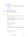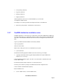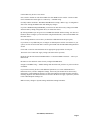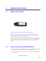
1
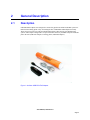
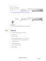
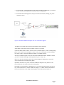
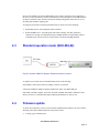
PIRANHA USB ADAPTERS™ FAMILY Amfeltec USB-FXO Adapter Amfeltec USB-FXS Adapter User Manual May 23, 2014 Revision 2.0 www.amfeltec.com Copyright 2014 Amfeltec Corp. Contents Contents 1 About this Document ..................................................................................................... 1 1.1 Purpose ...................................................................................................................... 1 1.2 Feedback.................................................................................................................... 1 1.3 Revision History.......................................................................................................... 1 2 General Description ...................................................................................................... 2 2.1 Description ................................................................................................................. 2 2.2 Features ..................................................................................................................... 3 3 Requirements & Installation .......................................................................................... 4 3.1 Requirements ............................................................................................................. 4 3.2 Installation .................................................................................................................. 4 3.2.1 Hardware Installation ............................................................................................... 4 3.2.2 Software Installation ................................................................................................ 4 3.2.3 Channels Configuration ........................................................................................... 5 3.2.4 Starting Driver ......................................................................................................... 6 3.2.5 Stopping Driver ........................................................................................................ 7 3.2.6 Additional Driver Parameters .................................................................................. 7 3.2.7 FreePBX distribution installation notes .................................................................... 8 4 Operation Instructions ................................................................................................. 10 4.1 Rotary switch setting ................................................................................................ 10 4.2 Fail-over operation mode (SKU-082-01) .................................................................. 10 4.3 Standard operation mode (SKU-082-02) ................................................................. 12 4.4 Firmware update ...................................................................................................... 12 4.5 Led indicator ............................................................................................................. 13 5 Ordering Information ................................................................................................... 15 5.1 Standard package .................................................................................................... 15 5.1.1 SKU-082-01 – USB-FXO Adapter (with Fail-over support) ................................... 15 5.1.2 SKU-082-01 – USB-FXO Adapter (without Fail-over support) .............................. 15 5.1.3 SKU-083-01 – USB-FXS Adapter ........................................................................ 15 6 Appendix A: Limited warranty ..................................................................................... 16 7 Appendix B: Available analog lines operation modes ................................................. 17 User Manual, Revision 2.0 Page ii Contents Figures Figure 1: Amfeltec USB-FXO Adapter ................................................................................ 2 Figure 2: Amfeltec USB-FXO Adapter Connection scheme ............................................... 3 Figure 3: Amfeltec USB-FXS Adapter Connection scheme ................................................ 3 Figure 4: Amfeltec USB-FXO Adapter. Bottom side with Rotary switch ........................... 10 Figure 5: Amfeltec USB-FXO Adapter. Fail-over connection scheme .............................. 11 Figure 6: Amfeltec USB-FXO Adapter. Standard connection scheme.............................. 12 User Manual Revision 2.0 Page iii 1 About this Document 1.1 Purpose This document describes installation, features, specification and operation for AMFELTEC USBFXO/FXS Adapters. 1.2 Feedback AMFELTEC Corp. makes every effort to ensure that the information contained in this document is accurate and complete at time of release. Please contact AMFELTEC Corp. if you find any errors, inconsistence or have trouble understanding any part of this document. To provide your feedback, please send an email to [email protected] Your comments or corrections are greatly valued in our effort for excellence and continued improvement. 1.3 Revision History Rev. No. Description 1.0 Initial Release 2.0 FXO/FXS Adapters User Manual Rev. Date January 14, 2014 May 23, 1914 User Manual, Revision 2.0 Page 1 2 General Description 2.1 Description USB-FXO/FXS Adapters were designed to connect the popular Asterisk®-based PBX system to a PSTN line and analog phone. They are heading the line of PIRANHA USB Adapters™ family. These devices provide a cost-effective PSTN/analog phone connection for telecommunication systems. Ultra compact design makes it a part of the cable between your PBX USB port and PSTN jack in the wall (USB FXO Adapter) or analog phone (USB FXS Adapter). Figure 1: Amfeltec USB-FXO/FXS Adapter User Manual, Revision 2.0 Page 2 Figure 2: Amfeltec USB-FXO Adapter connection diagram Figure 3: Amfeltec USB-FXS Adapter connection diagram 2.2 Features • Cost-effective PSTN/analog phone connection • Easy installation • USB 2.0 compliant • Supports multiple USB-FXO/FXS devices in one system • Low power consumption, powered via USB interface • Visual status indicator • Ultra-small implementation • Fail-over support (USB-FXO) • RoHS-compliant User Manual, Revision 2.0 Page 3 3 Requirements and Installation 3.1 Requirements To operate the USB-FXO/FXS Adapters you will need a PBX system in a Linux environment with Asterisk®, DAHDI, and Amfeltec’s USB driver installed. Currently, the driver supports Linux Kernel 2.6.x and 3.x, and DAHDI 2.5 to 2.9. 3.2 Installation The USB-FXO/FXS Adapters can be connected or disconnected at any time during software installation and operation. However, for successful DAHDI and Asterisk® operations it is necessary to plug in the Adapter before this software is initiated. 3.2.1 Hardware Installation Set the Rotary switch on the bottom of Adapter to desired 1-9 position. Detailed information about Rotary switch setting you can find in Operation Instructions section, below. To install USB-FXO/FXS Adapter just connect it to your PBX USB port. Connection via USB hub is not recommended. 3.2.2 Software Installation Switch to /usr/src folder • # cd /usr/src Download and install latest DAHDI release from asterisk.org. Download and install Asterisk® release from asterisk.org. Download latest amfeltec_usb driver release from amfeltec.com: • wget http://amfeltec.com/drivers/USB-FXO/amfeltec_usb-<version>.tgz • # tar xfz amfeltec_usb-<version>.tgz • # cd amfeltec_usb-<version> • # make DAHDI_DIR=/usr/src/dahdi-linux-<version> • # make install User Manual, Revision 2.0 Page 4 • # make boot If you use the FreePBX distribution, see special installation notes in FreePBX section, below. 3.2.3 Channels Configuration First, make necessary changes in /etc/dahdi/system.conf file. To create one FXO channel with FXS signaling for USB-FXO Adapter: • fxsks=1 • echocanceller=mg2,1 To create one FXS channel with FXO signaling for USB-FXS Adapter: • fxoks=2 • echocanceller=mg2,2 Next, make necessary changes in /etc/asterisk/chan_dahdi.conf file, for example: • context=from-dahdi • group=0 • echocancel=yes • signaling=fxs_ks • channel => 1 • context=from-internal • group=1 • echocancel=yes • signaling=fxo_ks • channel => 2 User Manual, Revision 2.0 Page 5 3.2.4 Starting Driver You do not need to start amf_usb driver manually when connecting Amfeltec USB-FXO/FXS Adapter. Generally, it will start on boot with DAHDI service. To start (restart) the driver manually, type in the following command: • # service dahdi restart (or /etc/init.d/dahdi restart) Check if the amf_usb driver was started: Loading DAHDI hardware modules: amf_usb: [OK] Shortly after start you will see the solid Red LED light inside USB-FXO PSTN connector or solid Grin LED light inside USB-FXS telephone connector. Next enter: • # service dahdi status (or /etc/init.d/dahdi status) If Amfeltec USB-FXO device was connected, DAHDI span was registered and the FXO channel was configured, you will see: ### Span 1: AMF_USB_FXO “AMF_USB_FXO 1” (MASTER) 1 FXO FXSKS (EC: MG2 - INACTIVE) If Amfeltec USB-FXS device was connected, DAHDI span was registered and the FXS channel was configured, you will see: ### Span 1: AMF_USB_FXS “AMF_USB_FXS 1” (MASTER) 1 FXS FXOKS (EC: MG2 - INACTIVE) Start Asterisk® portal: • # /usr/sbin/asterisk In Asterisk® CLI run DAHDI show channels command to see the channel is In Service. • *CLI> dahdi show channels On computer reboot amf_usb driver will start automatically with DAHDI service. User Manual, Revision 2.0 Page 6 3.2.5 Stopping Driver There is no need to stop amf_usb driver before disconnection of Amfeltec USB-FXO Adapter or before a computer shutdown. To unload driver manually you need to stop Asterisk® portal and DAHDI service: 3.2.6 • # asterisk -r • *CLI> core stop now • # service dahdi stop (or /etc/init.d/dahdi stop) Additional Driver Parameters Amfeltec USB driver can be launched with additional parameters: General: • opermode (default = FCC). Analog telephone line operation mode, depending on country. List of available modes - see Appendix B. • alawoverride (default = 0). Audio compression scheme. When set to 0, mulaw (North America). When set to 1, alaw (Europe). • dahdicfg_on (default=0). When this parameter is set to 1, driver calls dahdi_cfg command on connection and disconnection of Amfeltec USB-FXO devices. To prevent these calls, parameter should be left unchanged. USB-FXO: • battthresh (default = 3). Battery threshhold • battdebounce (default=64). Battery debounce • fxo_txgain (default=0) • fxo_rxgain (default=0) • watchdog_off (default=0). Fail-over relay watchdog operations. Enabled by default when set to 0, otherwise disabled. See Fail-over relay section of this manual for more information. USB-FXS: • fxs_txgain (default=0, can be set to 35 or -35) • fxs_rxgain (default=0, can be set to 35 or -35) User Manual, Revision 2.0 Page 7 • reversepolarity (default=0) • lowpower (default=0) • fastringer (default=0) • ringampl (default=0) All these parameters can be set in a normal DAHDI way, by a line under /etc/modprobe.d/dahdi.conf file. For example, to set current opermode and compression scheme to AUSTRALIA: • 3.2.7 options amf_usb opermode=”AUSTRALIA” alawoverride=1 FreePBX distribution installation notes FreePBX distribution is a convenient way to install Linux, Asterisk®, DAHDI and FreePBX GUI in a single install. However, to install amf_usb driver on this system you need to reinstall DAHDI from sources. This installation should be done not from GUI, but straight in Linux shell on your PBX. Login to your PBX and check DAHDI version already installed: # rpm -qa | grep dahdi Switch to /usr/src folder Install “make” utility just in case it is not installed on your system: • # yum install make Download and install appropriate DADHI release from asterisk.org, for example: • wget http://downloads.asterisk.org/pub/telephony/dahdi-linux-complete/dahdi-linuxcomplete-2.7.0+2.7.0.tar.gz Following DAHDI installation guide, run “make” and “make install” commands, but do not execute “make config”. Download and install Amfeltec USB driver (see instructions above). On this step do not make any changes to DAHDI and Asterisk® configuration files. Connect Amfeltec USB-FXO/FXS Adapter(s). Restart DAHDI service: • # service dahdi restart (or /etc/init.d/dahdi restart) User Manual, Revision 2.0 Page 8 Confirm that amf_usb driver was started. Next, switch to another PC and call FreePBX GUI from WEB browser window. Connect to PBX GUI as administrator and navigate to Connectivity -> DAHDI config. Carefully read the disclaimer: “DAHDI is DISABLED for writing”. Make a copy of configuration files before clicking ENABLE button and making any changes. If you leave DAHDI writing DISABLED, you will need to make all necessary changes in DAHDI and Asterisk® by editing configuration files (see instructions above). By clicking ENABLE you will get access to DAHDI GUI module and the warning “You have new hardware! Please configure your new hardware using the Edit button(s). Then reload DAHDI with the button below”. Check Analog Hardware section. There you should see additional FXO/FXS port (ports). If you do not see any additional port, reconfigure /etc/dahdi/system.conf file in accordance to your system, save this file and restart PBX. Connect again to PBX and check DAHDI Analog Hardware section. Click “Edit” Action for FXO/FXS Ports and set appropriate group number for each port. Then click “Save” button and “Apply Config”(red button on the top menu). DO NOT click “Reload Asterisk DAHDI module” or “Restart DAHDI & Asterisk” – reboot your PBX instead. Reconnect to GUI and check status of newly configured DAHDI Ports. Navigate to DAHDI Config -> Module Settings and check that amf_usb driver is present in the list of modules. If you need to run amf_usb driver with additional parameters (see section Additional Driver Parameters above), switch to Modprobe Settings, choose amf_usb module and set all necessary parameters in “Other Modprobe Settings” list. Note that changing Opermode and other settings by switching dropdown lists and checkboxes will not affect the driver. To apply a parameter you need to fill “Other Modprobe Settings” list. Make necessary changes in System Settings and Global Settings bookmarks. User Manual, Revision 2.0 Page 9 4 Operation Instructions 4.1 Rotary switch setting Figure 4: Amfeltec USB-FXO Adapter. Bottom side with Rotary switch The Rotary switch on the bottom of the Adapter has 0 to 9 settings. Setting 0 is used only for Firmware update operation (see below). In normal operational mode the switch should be set to any position from 1 to 9. Default setting when delivered is 1. The position of the switch defines the order of DAHDI spans registration. If you have more than one Amfeltec USB Adapter, you can choose different positions of the switch for different USB Adapters. The Adapters with less significant Rotary switch position will register their DAHDI spans first. 4.2 Fail-over operation mode (SKU-082-01) Fail-over system can automatically switch the PSTN line to a backup analog phone in case of PBX server failure or power outage. This connection scheme gives multiple advantages: • Rings from backup phone on incoming calls indicates your PBX system failure, and allows you to answer calls User Manual, Revision 2.0 Page 10 • In an emergency, your backup phone will be connected to PSTN automatically, so you do not need to reconnect the telephone line manually to make an outgoing call • In normal mode the backup phone is always disconnected from PSTN, making your phone connections secure. Figure 5: Amfeltec USB-FXO Adapter. Fail-over connection diagram To organize your system work in a Fail-over mode please do the following: Set the Rotary switch on the bottom of Adapter to desired 1-9 position. Connect the Phone Splitter to RJ11 connector of the USB-FXO Adapter. Connect a backup analog phone to the “Phone” jack of the Splitter. Connect “Line” jack of the Splitter to PSTN telephone line via RJ11 cable. Connect the USB-FXO Adapter to your PBX USB port. Switch on your PBX computer. Soon after Asterisk®, DAHDI and Amfeltec USB driver started, you will see solid Red LED light, indicating that FXO port is ready to use. Please note, that the Line/Phone splitter alone (without USB-FXO Adapter) does not provide access to PSTN line from backup analog phone. By default, when there is no power on Amfeltec USB-FXO Adapter or amf_usb driver is not started, PSTN line will remain connected to backup phone. When PBX is ON and Amfeltec USB-FXO driver is in a normal operational mode, the Fail-over relay connects PSTN line to Amfeltec USB-FXO Adapter, i.e. to PBX. Solid red LED indicator shows the normal status of the Adapter. Backup phone is disconnected from PSTN line. User Manual, Revision 2.0 Page 11 In case of any hardware or software PBX failure (power outage, Asterisk® service stopping etc.) the fail-over relay automatically switches the PSTN line to the backup phone. Red LED indication on adapter switched to OFF. From this moment the backup analog phone will be able to receive incoming calls and make outgoing calls. To bring the system back to normal operational mode you can do one of the following: 4.3 • Restart PBX system. Asterisk® portal will be reloaded • Restart DAHDI service. Asterisk® portal will remain working. After this operation is completed we strongly recommend checking of DAHDI channels for functionality. Most of Asterisk® portal versions need to be restarted after restoration of DAHDI channels. Standard operation mode (SKU-082-02) Figure 6: Amfeltec USB-FXO Adapter. Standard connection scheme To organize your system work in a Standard mode please do the following: Set the Rotary switch on the bottom of Adapter to desired 1-9 position. Connect the USB-FXO Adapter to PSTN telephone line and to your PBX USB port. Switch ON your PBX computer. Soon after Asterisk®, DAHDI, and Amfeltec USB driver have started, you will see a solid Red LED light, indicating that FXO port is ready for use. 4.4 Firmware update To check current Firmware version of your Amfeltec USB-FXO/FXS Adapter you need to run the following Linux shell command right after amf_usb driver start: • # dmesg | grep “USB Firmware” User Manual, Revision 2.0 Page 12 To update Firmware, please download new firmware file from amfeltec.com: • # cd /usr/src/amfeltec_usb<version>/firmware For USB FXO Adapter: • # wget http://amfeltec.com/home/products/downloads/amfeltec_usb/USB_FXO_064V<firmware ver>.BIN For USB FXS Adapter: • # wget http://amfeltec.com/home/products/downloads/amfeltec_usb/USB_FXS_064V<firmware ver>.BIN Prior to Firmware update operation you need to stop Asterisk portal: • # asterisk -r • *CLI> core stop now Disconnect Amfeltec USB Adapter, and set Rotary switch to 0. Reconnect Adapter to USB port. Note that only one Amfeltec USB-FXO/FXS Adapter should be connected to PC for firmware update operation. Red and green LED lights should be blinking during the update operation. Execute Firmware update script: • # ./amf_firmware_update.sh Follow further instructions on the screen. Do not disconnect device during Firmware update operation. After the update is finished, disconnect Amfeltec USB Adapter, and set the rotary switch to desired 1-9 position before reconnecting it for further use. 4.5 LED indicator The LED indicators locate inside Adapter’s RJ11 connector and provide you with the following status information: • No lights: Adapter is not connected to USB port, or Amfeltec USB device driver does not work • Solid Red: User Manual, Revision 2.0 Page 13 FXO Adapter is connected and ready for use • Solid Green: FXS Adapter is connected and ready for use • Blinking Red and Green: Adapter is in Firmware update mode User Manual, Revision 2.0 Page 14 5 Ordering Information 5.1 Standard package Standard package include the following components: 5.1.1 5.1.2 5.1.3 SKU-082-01 – USB-FXO Adapter (with Fail-over support) • USB-FXO Adapter (1) • Splitter (1) • RJ11 Cable (1) • USB Cable (1) SKU-082-02 – USB-FXO Adapter (without Fail-over support) • USB-FXO Adapter (1) • RJ11 Cable (1) • USB Cable (1) SKU-083-01 – USB-FXS Adapter • USB-FXS Adapter (1) • RJ11 Cable (1) • USB Cable (1) User Manual, Revision 2.0 Page 15 6 Appendix A: Limited warranty AMFELTEC Corporation does not warrant that the operation of the hardware, software or firmware products will be uninterrupted or error free. AMFELTEC products are not intended to be used as critical components in life support systems, aircraft, military systems or other systems whose failure to perform can reasonably be expected to cause significant injury to humans. AMFELTEC expressly disclaims liability for loss of profits and other consequential damages caused by the failure of any product which would cause interruption of work or loss of profits, such as shipboard or military attachment. THIS LIMITED WARRANTY IS IN LIEU OF ALL OTHER WARRANTIES, EXPRESSED OR IMPLIED. THE WARRANTIES PROVIDED HEREIN ARE BUYER’S SOLE REMEDIES. IN NO EVENT SHALL AMFELTEC CORPORATION BE LIABLE FOR DIRECT, SPECIAL, INDIRECT, INCIDENTAL OR CONSEQUENTIAL DAMAGES SUFFERED OR INCURRED AS A RESULT OF THE USE OF, OR INABILITY TO USE THESE PRODUCTS. THIS LIMITATION OF LIABILITY REMAINS IN FORCE EVEN IF AMFELTEC CORPORATION IS INFORMED OF THE POSSIBILITY OF SUCH DAMAGES. Some states do not allow the exclusion or limitation on incidental or consequential damages, so the above limitation and exclusion may not apply to you. This warranty gives you specific legal rights, and you may also have other rights which vary from state to state. User Manual, Revision 2.0 Page 16 7 Appendix B: Available analog lines operation modes "FCC" (US, Canada), "TBR21" (Austria, Belgium, Denmark, Finland, France, Germany, Greece, Iceland, Ireland, Italy, Luxembourg, Netherlands, Norway, Portugal, Spain, Sweden, Switzerland, UK), "ARGENTINA", "AUSTRALIA", "AUSTRIA", "BAHRAIN", "BELGIUM", "BRAZIL", "BULGARIA", "CANADA", "CHILE", "CHINA", "COLUMBIA", "CROATIA", "CYPRUS", "CZECH", "DENMARK", "ECUADOR", "EGYPT", "ELSALVADOR", "FINLAND", "FRANCE", "GERMANY", "GREECE", "GUAM", "HONGKONG", "HUNGARY", "ICELAND", "INDIA", "INDONESIA", "IRELAND", "ISRAEL", "ITALY", "JAPAN", "JORDAN", "KAZAKHSTAN", "KUWAIT", "LATVIA", "LEBANON", "LUXEMBOURG", "MACAO", "MALAYSIA", "MALTA", "MEXICO", "MOROCCO", "NETHERLANDS", "NEWZEALAND", "NIGERIA", "NORWAY", "OMAN", "PAKISTAN", "PERU", "PHILIPPINES", "POLAND", "PORTUGAL", "ROMANIA", "RUSSIA", "SAUDIARABIA", "SINGAPORE", "SLOVAKIA", "SLOVENIA", "SOUTHAFRICA", "SOUTHKOREA", "SPAIN", "SWEDEN", "SWITZERLAND", "SYRIA", "TAIWAN", "THAILAND", "UAE", "UK", "USA", "YEMEN" User Manual, Revision 2.0 Page 17