1
•
You must set the House ID only if you are using RF keypads and/or bi-directional devices; AND the House
ID Source is the FA260RF (Local).
FA260RF Application Guide
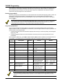
Below is a guide that outlines how to program the wireless keys, RF receiver, and the House ID in the FA260RF
for your particular installation.
Control Panel
Are you using
RF keys beyond
system’s
capacity?
RF receivers
beyond system’s
capacity?
RF keypads and/or
Bi-directional
devices on more
than 1 partition?
FA110C, FA120C
N/A
N/A
N/A
Local
FA142C, FA148C
NO
YES
YES
NO
NO
YES
N/A
N/A
N/A
Use Programming Without Local Wireless Keys
Local
Enable [1]
System [1]
Local
Disable [0]
Local [0]
FA162C
NO
YES
YES
NO
YES
NO
NO
YES
YES
YES
NO
NO
NO
YES*
YES*
Use Programming Without Local Wireless Keys
Local
Enable [1]
System [1]
Local
Disable [0]
Local [0]
System
Disable [0]
Local [0]
Local
Disable [0]
Local [0]
FA1220CV,
FA1340C,
FA1600CA
NO
YES
YES
NO
YES
NO
NO
YES
YES
YES
NO**
NO**
NO**
YES
YES
Use Programming Without Local Wireless Keys
Local
Enable [1]
System [1]
Local
Disable [0]
Local [0]
System
Disable [0]
Local [0]
Local
Disable [0]
Local [0]
Program
Wireless Keys
As
Program
RF
Receiver
Disable
House ID
Source***
As
Local [0]
* Two FA260RFs are needed for this application. One connected to partition 1’s keypad terminals and one connected to partition 2’s.
** If using an RF keypad on only one partition, the FA260RF’s partition assignment must match the partition set in field 1*48.
*** If set for Local on a partition control, the FA260RF’s partition assignment must match the partition programmed in the BD device.
Installing the FA260RF
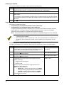
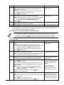
Locate the FA260RF in an area and at a height where it is convenient for users to operate the system. The
FA260RF must be at least 10' from the control panel to ensure proper operation of the RF receiver.
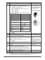
To install the FA260RF, refer to Figure 1 for wiring
connections and perform the following steps:
Step
1
C +
NO
3
D +
_
4
+
+
2
+
+ +
DO
TAMPER
SWITCH
5
6
7
Figure 1: FA260RF Wiring Connections
2
Action
Remove the case back by pushing down
the two snaps along the FA260RF’s
bottom edge and pulling the case apart.
Route the wiring from the control panel
through the opening in the case back.
(See the control panel’s instructions for
proper wire run lengths.)
Mount the case back directly to a wall or
electrical gang box.
Connect the power and data wires from
the control panel to the terminals on the
FA260RF.
Connect the wires for the relay output (if
being used) to the terminals on the
FA260RF’s PC board.
Reattach the keypad to its case back.
Remove the clear protective films from
the LCD display and install the keypad
labels, as required.
NOTE: Upon power up or exit of the Program
mode, the FA260RF alternately flashes "Ad" and the
2-digit keypad address and the 2-digit receiver
address on the display. Press any key to display the
system status.