1
A BELDEN Brand
™
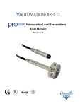
CopperHead FS-790
Camera-Mounted ENG/EFP Fiber Optic Transceiver System
for JVC GY-HM790HD Camcorder
User Manual
Systems
FS-790PNACG
FS-790PSACG
FS-790TNCG
FS-790PNARG
FS-790PSARG
FS-790TNRG
FS-790PNVCG
FS-790PSVCG
FS-790PNVRG
F -790PSVRG
Camera Units
KA-F790NG
KA-F790SG
Base Stations
RM-FP790PNCG
RM-FP790TNCG
RM-FP790PNRG
RM-FP790TNRG
RM-FP790PSCG
RM-FP790PSRG
Power Wafers
KA-PW790AG
KA-PW790VG
External MPS Power Supplies
CH3-MPS-95VD-2ST-NEU
CH3-MPS-95VD-NEU-NEU
CH3-MPS-95VD-2ST-304
CH3-MPS-95VD-NEU-304
Telecast Fiber Systems, Inc.
102 Grove Street
Worcester, MA 01605
Tel: 508-754-4858
Fax: 508-752-1520
www.telecast-fiber.com
v2-110121jh (preliminary)
Table of Contents
ABOUT THIS USER GUIDE ........................................................................................................................... 5
CHAPTER 1. IMPORTANT INFORMATION.......................................................................................... 7
1.1.
Warranty........................................................................................................................................................... 7
1.2.
Safety and Fiber Optic Systems ......................................................................................................................... 8
Optical Fiber Safety ........................................................................................................................................................... 8
Power Fuses ...................................................................................................................................................................... 8
Unpacking and the CopperHead FS-790 Transceiver System.......................................................................................... 9
1.3.
Product Returns .............................................................................................................................................. 10
CHAPTER 2. – SYSTEM OVERVIEW .....................................................................................................11
2.1.
Fiber Cable Concepts....................................................................................................................................... 12
Fiber Optic Cable ............................................................................................................................................................. 12
Fiber Optic Connector Types ........................................................................................................................................... 13
2.2.
CopperHead FS-790 Transceiver System concepts........................................................................................... 14
2.3.
Signal paths in the CopperHead FS-790 Transceiver System ............................................................................ 15
2.4.
CopperHead FS-790 Transceiver System Components..................................................................................... 16
CopperHead KA-F790 Camera Unit Overview................................................................................................................. 16
CopperHead RM-FP790 Base Station .............................................................................................................................. 16
CopperHead FS-790 Transceiver System Additional Components.................................................................................. 17
CHAPTER 3. INSTALLATION OF THE COPPERHEAD KA-F790 CAMERA UNIT ON THE JVC
PROHD GY-HM790 VIDEO CAMERA ......................................................................................................19
3.1.
Initial Installation of the CopperHead KA-F790 Camera Unit to the Camera.................................................... 19
Verification of All Components ....................................................................................................................................... 20
Relocation of the Battery Adaptor from the Camera to the KA-F790 Camera Unit........................................................ 21
Installation Of The Camera Unit Mounting Plate On To The Camera ............................................................................. 23
Installation Of The Connector Adaptor Plate And Connection Of Required Cables........................................................ 24
Mounting Of the Camera Unit On To the Mounting Plate .............................................................................................. 25
Operational Test Of The Installed System....................................................................................................................... 25
3.2.
Mounting Power Wafer Unit to the CopperHead KA-F790 Camera Unit.......................................................... 26
3.3.
Relocation of the CopperHead RM-FP790 Base Station fiber connector .......................................................... 27
Telecast Fiber Systems – CopperHead FS790 ProHD Transceiver System User Guide –110124V4JH
Page 1
CHAPTER 4. COPPERHEAD FS-790 TRANSCEIVER SYSTEM DETAILED DESCRIPTION ....29
4.1.
CopperHead KA-F790 Camera Unit.................................................................................................................. 29
CopperHead KA-F790 Camera Unit Connector Area –Connectors ................................................................................. 30
CopperHead KA-F790 Camera Unit Indicator and Control Panel.................................................................................... 33
4.2.
CopperHead FS-790 Base Station .................................................................................................................... 35
CopperHead FS-790 Base Station Front Panel ................................................................................................................ 35
CopperHead RM-FP790 Base Station Front Panel – Identifying Controls & Connectors ................................................ 35
CopperHead RM-FP790 Base Station Back Panel............................................................................................................ 39
CopperHead RM-FP790 Base Station Front Panel – Identifying Controls & Connectors ................................................ 39
External Power Options................................................................................................................................................... 39
Internal Power Options ................................................................................................................................................... 40
4.3.
Additional CopperHead FS-790 Transceiver System Items............................................................................... 41
“Power Wafer” Camera Adaptor..................................................................................................................................... 42
MPS External Power Wafer Power Supply ...................................................................................................................... 43
CHAPTER 5. CONNECTION OF THE COPPERHEAD FS-790 TRANSCEIVER SYSTEM ...........45
5.1.
Connections between the CopperHead RM-FP790 Base Station and the KA-F790 Camera Unit ..................... 45
Tactical Fiber between the Base Station and Camera Unit............................................................................................. 46
SMPTE Hybrid Fiber between the Base Station (powered) and Camera Unit................................................................. 47
SMPTE Hybrid Fiber between Base Station and Camera Unit (Infrastructure Wiring) ................................................... 48
SMPTE Hybrid Fiber between the MPS Power Unit and Camera Unit ............................................................................ 49
5.2.
Connections to the CopperHead RM-FP790 Base Station ................................................................................ 50
Multi-Pin Cable Assemblies Used with the CopperHead FS-790 Base Station................................................................ 50
Connectors into and out of the CopperHead FS-790 Base Station ................................................................................. 51
5.3.
Connections to the CopperHead FS-790 Camera Unit...................................................................................... 53
Connectors into and out of the CopperHead FS-790 Camera Unit Back Side ................................................................. 53
5.4.
Camera Unit Connection Example ................................................................................................................... 55
Camera Unit (Camera Facing Side) to Camera Connections ........................................................................................... 55
CHAPTER 6. OPERATION OF THE COPPERHEAD FS-790 TRANSCEIVER SYSTEM..............57
6.1.
Set Up of the CopperHead FS-790 Transceiver System for operation .............................................................. 58
6.2.
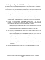
Connecting and Managing the Fiber Cable ...................................................................................................... 59
Planning the Fiber Cable Route....................................................................................................................................... 59
Running the Fiber Cable .................................................................................................................................................. 60
6.3.
Powering the System ...................................................................................................................................... 62
Powering the CopperHead FS-790 Base Station ............................................................................................................. 62
Powering the CopperHead FS-790 Camera Unit ............................................................................................................. 62
Telecast Fiber Systems – CopperHead FS790 ProHD Transceiver System User Guide –110124V4JH
Page 2
6.4.
Intercom ......................................................................................................................................................... 63
6.5.
Using the Digital Displays ................................................................................................................................ 65
A Brief Guide to Measurement of Fiber Optic Signal Strength ....................................................................................... 65
The CopperHeadFS-790 Base Station Digital Display ...................................................................................................... 65
6.6.
Standard Operation......................................................................................................................................... 69
6.7.
Shutting Down the System .............................................................................................................................. 70
6.8.
Troubleshooting.............................................................................................................................................. 71
APPENDICES ..................................................................................................................................................72
APPENDIX 1. CONNECTOR PIN ASSIGNMENTS ...............................................................................72
1.1.
CopperHead FS-790 Base Station Connectors.................................................................................................. 72
Camera Remote – Base Station DB9 Connector -Wiring................................................................................................. 72
Tally/GPI/Data – Base Station DB15 Connector Wiring .................................................................................................. 72
Base Station Audio Inputs & Outputs Connector Wiring ................................................................................................ 73
Power Connector – Base Station 4 Pin XLR Connector Wiring........................................................................................ 73
Power Connector – Base Station Fused AC Receptacle .................................................................................................. 74
Base Station 12VDC Terminal Block Wiring..................................................................................................................... 74
Clear-Com Intercom – Base Station 3 Pin XLR Connector Wiring ................................................................................... 74
RTS Intercom – Base Station 3 Pin XLR Connector Wiring .............................................................................................. 74
1.2.
CopperHead FS-790 Camera Unit Multi-Pin Connectors .................................................................................. 75
Power Wafer – Camera Unit 4 Pin Lemo Connector Wiring ........................................................................................... 75
Camera Headset – Camera Unit 5 Pin XLR Female Connector Wiring ............................................................................ 75
Audio Out ........................................................................................................................................................................ 75
APPENDIX 2. BASE STATION REMOTE CONTROL CABLE............................................................76
APPENDIX 3. AUDIO CABLE WIRING SUGGESTIONS.....................................................................77
CopperHead FS-790 Base Station 25-Pin Audio Input Cable........................................................................................... 77
CopperHead FS-790 Base Station 25-Pin Audio Output Cable........................................................................................ 77
APPENDIX 4. SPECIFICATION ...............................................................................................................78
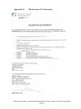
APPENDIX 5. DECLARATION OF CONFORMITY ..............................................................................79
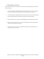
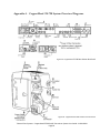
APPENDIX 6. COPPERHEAD FS-790 SYSTEM OVERVIEW DIAGRAMS....................................81
Telecast Fiber Systems – CopperHead FS790 ProHD Transceiver System User Guide –110124V4JH
Page 3
List of Main Figures
FIGURE 1 - TACTICAL FIBER OPTIC CABLE CROSS-SECTION (ILLUSTRATIVE ONLY) .............................................................. 12
FIGURE 2 - HYBRID FIBER OPTIC CABLE CROSS-SECTION (ILLUSTRATIVE ONLY) ................................................................. 12
FIGURE 3 - FIBER OPTIC CONNECTORS ................................................................................................................................ 13
FIGURE 4- BASE STATION TO CAMERA UNIT CONNECTION ................................................................................................ 15
FIGURE 5 - CAMERA UNIT: CONNECTOR PANELS ................................................................................................................ 16
FIGURE 6 – CAMERA UNIT: INDICATOR AND INTERCOM LEVEL CONTROL PANEL .............................................................. 16
FIGURE 7 - BASE STATION: FRONT INDICATOR PANEL ........................................................................................................ 16
FIGURE 8 - BASE STATION: REAR CONNECTOR PANEL ....................................................................................................... 16
FIGURE 9 - MOUNTING THE POWER WAFER UNIT TO THE COPPERHEAD FS-790 CAMERA UNIT ...................................... 26
FIGURE 10 - CONNECTING THE POWER WAFER .................................................................................................................. 26
FIGURE 11 - COPPERHEAD RM-FP790 BASE STATION WITH REAR MOUNTED FIBER CONNECTOR .................................... 27
FIGURE 12 - COPPERHEAD RM-FP790 BASE STATION WITH FRONT MOUNTED FIBER CONNECTOR.................................. 27
FIGURE 13 - COPPERHEAD FS-790 CAMERA UNIT BACK SIDE ............................................................................................. 29
FIGURE 14 - COPPERHEAD FS-790 BASE STATION FRONT PANEL........................................................................................ 35
FIGURE 15 - FIBER CONNECTOR TYPES ................................................................................................................................ 35
FIGURE 16 - COPPERHEAD RM-FP790 BASE STATION BACK PANEL (POWERED VERSION) ................................................. 39
FIGURE 17 - MPS EXTERNAL POWER WAFER POWER SUPPLY ............................................................................................ 43
FIGURE 18 - TACTICAL FIBER BETWEEN THE BASE STATION AND CAMERA UNIT ............................................................... 46
FIGURE 19 - SMPTE HYBRID FIBER BETWEEN THE BASE STATION (POWERED) AND CAMERA UNIT .................................. 47
FIGURE 20 - SMPTE HYBRID FIBER BETWEEN BASE STATION AND CAMERA UNIT (INFRASTRUCTURE WIRING)................ 48
FIGURE 21 - SMPTE HYBRID FIBER BETWEEN THE MPS POWER UNIT AND CAMERA UNIT ................................................ 49
FIGURE 22 - COPPERHEAD FS-790 BASE UNIT CONNECTIONS ............................................................................................ 50
FIGURE 23 - COPPERHEAD FS-790 CAMERA UNIT BACK SIDE CONNECTIONS..................................................................... 53
FIGURE 24 - CAMERA UNIT (CAMERA FACING SIDE) TO CAMERA CONNECTIONS.............................................................. 55
FIGURE 25 – INTERCOM AND TALLY CONTROLS/INDICATORS ............................................................................................ 63
FIGURE 26 - COPPERHEAD JVC FP-790 SERIES BASE STATION REMOTE CABLE................................................................... 76
FIGURE 27 - COPPERHEAD FP-790 BASE STATION 25-PIN AUDIO INPUT CABLE ................................................................. 77
FIGURE 28 - COPPERHEAD FP-790 BASE STATION 25-PIN AUDIO OUTPUT CABLE.............................................................. 77
FIGURE 29 - COPPERHEAD FS-790 BASE STATION REAR PANEL .......................................................................................... 81
FIGURE 30 - COPPERHEAD FS-790 CAMERA UNIT CONNECTORS........................................................................................ 81
FIGURE 31 - COPPERHEAD FS-790 CAMERA UNIT INDICATORS AND CONTROLS................................................................ 83
FIGURE 32 - COPPERHEAD FS-790 BASE STATION FRONT PANEL........................................................................................ 83
Telecast Fiber Systems – CopperHead FS790 ProHD Transceiver System User Guide –110124V4JH
Page 4
List of Tables
TABLE 1 - WHAT IS SHIPPED WITH A COPPERHEAD FS-790 SYSTEM..................................................................................... 9
TABLE 2 - FIBER OPTIC CONNECTOR TYPES & USAGE.......................................................................................................... 13
TABLE 3 - MPS POWER SUPPLY ADAPTOR OPTIONS ........................................................................................................... 43
TABLE 4 - COPPERHEAD FS-790 POWER OPTIONS ............................................................................................................. 45
TABLE 5 - BASE STATION CAMERA REMOTE CONNECTOR WIRING..................................................................................... 72
TABLE 6 - BASE STATION TALLY/GPI CONNECTOR WIRING ................................................................................................. 72
TABLE 7 - BASE STATION AUDIO 25 PIN CONNECTOR WIRING ........................................................................................... 73
TABLE 8 - BASE STATION POWER CONNECTOR WIRING ..................................................................................................... 73
TABLE 9 - BASE STATION 12VDC TERMINAL BLOCK WIRING ............................................................................................... 74
TABLE 10 - BASE STATION CLEAR-COM INTERCOM OUTPUT WIRING ................................................................................ 74
TABLE 11 - BASE STATION RTS INTERCOM OUTPUT WIRING .............................................................................................. 74
TABLE 12 - CAMERA UNIT POWER WAFER CONNECTOR WIRING....................................................................................... 75
TABLE 13 - CAMERA UNIT HEADSET CONNECTOR WIRING ................................................................................................. 75
TABLE 14 - STANDARD XLR3 AUDIO CONNECTOR WIRING ................................................................................................. 75
About this User Guide
The CopperHead RM-FP790 Fiber Optic Transceiver System can be delivered in a number of configurations
depending on the Power and Battery Mount options selected. This user guide is designed to cover all of the
various options and so not every page in this guide will apply to your specific system.
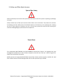
Throughout this guide a number of informational pointers are used to mark important or useful information.
Caution – the information provided is important safety information and
should be understood and followed in order to operate the CopperHead FS790 Fiber Optic Transceiver System safely and properly.
Useful information regarding the User Guide and the CopperHead FS-790 Fiber
Optic Transceiver System. Reading and understanding this information will
make using the manual and the product easier.
Telecast Fiber Systems – CopperHead FS790 ProHD Transceiver System User Guide –110124V4JH
Page 5
Page Intentionally Left Blank
Telecast Fiber Systems – CopperHead FS790 ProHD Transceiver System User Guide –110124V4JH
Page 6
Chapter 1.
Important Information
1.1. Warranty
LIMITED WARRANTY STATEMENT
Telecast Fiber Systems, Inc. (“Telecast”) expressly warrants to Buyer that the Products supplied shall be free from
defects in materials and workmanship for a period of 12 months following the date the Products are delivered to Buyer
(the “Warranty Period”). Telecast's liability under this limited warranty shall be limited, at its option, to providing refund
of purchase price for Products, or replacing or repairing Products shown to be defective either in materials or
workmanship. Buyer's sole and exclusive remedy for breach of warranty shall be such refund, replacement or repair.
A claim of defect in materials or workmanship in any Product shall be allowed only when it is submitted in writing to
Telecast Fiber Systems, Inc. within seven days after discovery of the defect, and in any event within the Warranty
Period. No claim shall be allowed in respect of any Product which has been altered, neglected, damaged or stored in any
manner which adversely affects it. In order to obtain service under the terms of this warranty, Distributor’s customer or
Distributor must notify Telecast of the defect prior to the expiration of the applicable warranty period and obtain a
Return Authorization Number from Telecast. In no event may products be returned to Telecast or to Distributor for
warranty service without having obtained from Telecast a Return Authorization Number.
This limited warranty applies only to new and unused Products delivered to Buyers located within the United States of
America, or to international Buyers if sold through an authorized Distributor organization, and shall not extend to any
equipment not manufactured by Telecast Fiber Systems, Inc., even though such equipment may be sold or operated
with the Products. In addition, this limited warranty shall be void and of no further force or effect whatsoever if the
Product is repaired or modified by any person other than an authorized representative of Telecast Fiber Systems, Inc.
without the consent of Telecast Fiber Systems, Inc. This warranty shall not apply to any defect, failure or damage caused
by improper use or inadequate maintenance and care. Nor shall this warranty apply to any damage caused in whole or
in part by attempts by personnel other than Telecast’s personnel, as approved in advance in accordance with the
foregoing provisions, to open, install, repair, or service the Product; nor to damage resulting from improper connection
with incompatible equipment; nor to damage to a unit which has been modified by personnel other than Telecast
personnel.
Products returned to Telecast for warranty service shall be shipped, freight prepaid to Telecast. Telecast will return the
repaired product or ship a replacement, freight prepaid, to either Distributor or Distributor’s customer, as requested by
Distributor’s customer, at a location within the United States or, at Telecast’s option, to Distributor’s location in the case
of international sales. This limited warranty shall also apply to Products that replace defective Products and Products
that have been repaired by authorized representatives of Telecast Fiber Systems, Inc., but only for the original Warranty
Period. The Warranty Period shall not be extended by reason of defect, or any period of time during which the Product
is not available to Buyer because of defects or repairs, without the express written consent of Telecast Fiber Systems,
Inc.
EXCEPT FOR THE EXPRESS LIMITED WARRANTY AGAINST DEFECTS IN MATERIALS AND WORKMANSHIP CONTAINED
HEREIN, TELECAST FIBER SYSTEMS, INC. MAKES NO WARRANTY OF ANY KIND WHATSOEVER, EXPRESS OR IMPLIED, AND
ALL WARRANTIES OF MERCHANTABILITY, FITNESS FOR A PARTICULAR PURPOSE, AND OTHER WARRANTIES OF
WHATEVER KIND ARE HEREBY DISCLAIMED BY TELECAST FIBER SYSTEMS, INC. THIS LIMITED WARRANTY SETS FORTH
EXCLUSIVELY ALL OF TELECAST FIBER SYSTEMS, INC.'S LIABILITY IN CONTRACT OR OTHERWISE IN THE EVENT OF A
DEFECTIVE PRODUCT. WITHOUT LIMITATION ON THE FOREGOING, TELECAST FIBER SYSTEMS, INC. EXPRESSLY
DISCLAIMS ANY LIABILITY WHATSOEVER FOR ANY DAMAGES INCURRED DIRECTLY OR INDIRECTLY IN CONNECTION WITH
THE SALE OR USE OF, OR OTHERWISE IN CONNECTION WITH, THE PRODUCT, INCLUDING WITHOUT LIMITATION, LOSS
OF PROFITS AND SPECIAL, INCIDENTAL OR CONSEQUENTIAL DAMAGES, WHETHER CAUSED BY NEGLIGENCE OR
OTHERWISE, REGARDLESS WHETHER TELECAST HAS BEEN GIVEN ADVANCE NOTICE OF THE POSSIBILITY THEREOF
THIS WARRANTY IS GIVEN BY TELECAST IN LIEU OF ANY OTHER WARRANTY EXPRESSED OR IMPLIED.
Telecast Fiber Systems – CopperHead FS790 ProHD Transceiver System User Guide –110124V4JH
Page 7
1.2. Safety and Fiber Optic Systems
Optical Fiber Safety
Never look directly into the end of the optical fiber while either end of the system is operating. Eye damage
can result.
Always use dust caps on fiber optic connectors when cables are not connected. This protects the connector
from damage and the unlikely event of accidental exposure of a human eye to an operating laser. Keeping
the caps in place when the connectors are not in use will also prevent dirt and dust from entering the
connector and degrading the performance of the optical link
Power Fuses
The CopperHead RM-FP790PNRG and RM-FP790PNCG Powered Base Stations are equipped with Dual
Cartridge fuses located next to the AC Power receptacle at the left rear of the unit. Refer to Page 74 for
specific fuse and location information.
NEVER operate the CopperHead RM-FP790P Powered Base Station without properly installed and rated
fuses. Severe electrical and heat damage could result as well as personal injury or death.
Telecast Fiber Systems – CopperHead FS790 ProHD Transceiver System User Guide –110124V4JH
Page 8
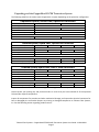
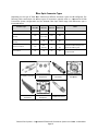
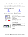
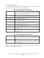
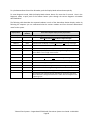
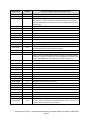
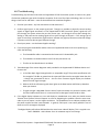
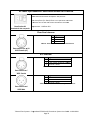
Unpacking and the CopperHead FS-790 Transceiver System
The following table lists the various items shipped with a system depending on the particular configuration.
Unpowered System, Tactical Fiber, OpticalCON Connectors
System Model:
CopperHead Camera Unit:
CopperHead Base Station:
Base Station Remote Cable:
12VDC power supply:
Base Intercom Interface:
FS-790TNRG
FS-790TNCG
KA-F790NG
RM-FP790TNRG
RM-FP790TNCG
VC-P790RMG
AA-FP790G
SYSTEM VARIABLES
RTS
Clear-Com
Powered System, Hybrid Fiber, OpticalCON Connectors
System Model:
CopperHead Camera Unit:
Power Wafer:
CopperHead Base Station:
Base Station Remote Cable:
Base Intercom Interface:
Power Wafer Battery Plate:
FS-790PNARG
FS-790PNVRG
FS-790PNACG
FS-790PNVCG
KA-F790NG
KA-PW790AG
KA-PW790VG
KA-PW790AG
KA-PW790VG
RM-FP790PNRG
RM-FP790PNCG
VC-P790RMG
SYSTEM VARIABLES
RTS
RTS
Clear-Com
Clear-Com
A/B Gold Mount
"V" Mount
A/B Gold Mount
"V" Mount
Powered System, Hybrid Fiber, SMPTE 304M Connectors
System Model:
CopperHead Camera Unit:
Power Wafer:
CopperHead Base Station:
Base Station Remote Cable:
FS-790PSARG
FS-790PSVRG
FS-790PSACG
FS-790PSVCG
KA-F790SG
KA-PW790AG
KA-PW790VG
KA-PW790AG
KA-PW790VG
RM-FP790PSRG
RM-FP790PSCG
VC-P790RMG
SYSTEM VARIABLES
Base Intercom Interface:
RTS
RTS
Clear-Com
Clear-Com
Power Wafer Battery Plate: A/B Gold Mount
"V" Mount
A/B Gold Mount
"V" Mount
Table 1 - What is shipped with a CopperHead FS-790 System
Please consult your packing slip and purchase order to insure that you have received all of the expected
Telecast Fiber Systems components.
Inspect all components for scratches and other mechanical damage, and inspect the electrical connectors for
bent or damaged pins and latches. Report any missing or damaged components to Telecast Fiber Systems,
Inc. See the following section regarding product returns.
Telecast Fiber Systems – CopperHead FS790 ProHD Transceiver System User Guide –110124V4JH
Page 9
You must use your own cables to make connections for Tally, Base Station audio, and other ancillary signals
and equipment. Suggestions for these cables are discussed later in this document.
Leave the protective caps on the optical connectors whenever the fiber is disconnected.
1.3. Product Returns
In the unlikely event of damage to your CopperHead FS-790 Fiber Optic Transceiver System during shipping
or delivery please note the damage with the delivery or shipping service and document the packaging and
product where you see damage. If any component does not work correctly out of the box please contact your
JVC sales organization.
If the problem cannot be remedied through a service telephone call an RMA (Return of Merchandise
Authorization) will be issued and you will receive an RMA number. Please note this RMA number inside and
outside of all shipping boxes and on all documentation provided with the items to be returned.
Telecast Fiber Systems – CopperHead FS790 ProHD Transceiver System User Guide –110124V4JH
Page 10
Chapter 2.
– System Overview
This chapter covers the following:
1) Fiber Optic Cable Concepts
2) CopperHead FS-790 Transceiver System concepts
3) Signal paths in the CopperHead FS-790 Transceiver System
4) CopperHead FS-790 Transceiver System Components
Telecast Fiber Systems – CopperHead FS790 ProHD Transceiver System User Guide –110124V4JH
Page 11
2.1. Fiber Cable Concepts
Fiber Optics and Fiber Optic Cable are the core technologies at the heart of the Telecast Fiber Systems
CopperHead FS-790 Transceiver System. The ability to multiplex and de
de-multiplex
multiplex a variety of video, audio
and data signals so that they can be carried over a thin strand of Fiber Optic cable for long distances enables
enable
the CopperHead System. The theory and oper
operation
ation of Fiber Optics is beyond the scope of this document.
What is important for the end user to be aware of are the different types of Fiber Optic Cable and Fiber Optic
Cable Connectors.
Fiber Optic Cable
Figure 1 - Tactical FFiber Optic Cable Cross-section (Illustrative only)
Tactical Fiber cable is heavy duty, Kevlar protected and capable of carrying CopperHead signals extended
distances. The cable can generally withstand a variety of environmental hazards such as being crushed
crush
or run-over.. Tactical Fiber can be used in the field mounted on Portable Fiber Reels in lengths up to 2000
feet.
Figure 2 - Hybrid Fiber Optic Cable Cross
Cross-section (Illustrative only)
Hybrid Fiber Cable has the same Fiber Op
Optic
tic characteristics with the addition of copper cables.
cables This
allows the transmission of power through the cable. This increases weight and reduces operating
distance. Hybrid Fiber Cable also includes a pair of Sense/Signal wires that allow systems to determine
deter
if
there is an open or shorted cable. Hybrid Fiber Cable is also larger in diameter then Tactical Fiber Cable
Telecast Fiber Systems – CopperHead FS790 ProHD Transceiver Sys
System
tem User Guide –110124V4JH
Page 12
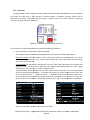
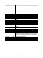
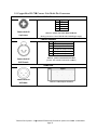
Fiber Optic Connector Types
Depending on the type of Fiber Optic Cable used, different Connector types can be configured. The
following table
ble summarizes the various types of connectors typically used in a CopperHead FS-790
Transceiver System configuration and the allowed Fiber Optic Cable usage. Each connector
conn
type is
illustrated below.
Tactical
Fiber Use
Hybrid
Fiber Use
Camera
Unit Use
Base
Station Use
SMPTE 304M
No
Yes
Yes
Yes
OpticalCON Cable Connector
(Neutrik)
Yes
Yes
(up to 95V)
Yes
Yes
OpticalCON Panel Connector
(Neutrik)
Yes
Yes
No
No
ST Fiber Connectors
Yes
Not
Typically
No
No
LC Connectors
No
No
No
No
Connector Type
Notes
Used with the FP-790
FP
System for
infrastructure wiring only
Infrastructure and Internal
Equipment Use
Table 2 - Fiber Optic Connector Types & Usage
ST Cable Connectors
SMPTE 304M
Connectors
ST Panel
Receptacles
OpticalCON Cable
Connectors
OpticalCON Panel
Receptacle
SMPTE 304M Panel
LC Cable Connectors
Receptacle
Figure 3 - Fiber Optic Connectors
Telecast Fiber Systems – CopperHead FS790 ProHD Transceiver Sys
System
tem User Guide –110124V4JH
Page 13
2.2.CopperHead FS-790 Transceiver System concepts
The Telecast CopperHead FS-790 Transceiver System is a camera video, audio and data multiplexing
system that installs between the JVC ProHD GY-HM790 video camera and its power source and connects
via a single fiber optic cable to a Base Station in a truck, studio control room, or other video production
facility. All video, audio and data usually carried on Triax or multi-core cable is sent, bi-directionally, over
a single lightweight fiber over distances as long as 5 km or more.
The Camera Unit is attached directly to the camera. A battery, battery power adaptor or a Telecast Fiber
Power Wafer power supply is attached to the Camera Unit. Battery mounts accommodated are the
Anton-Bauer and the V-Mount.
The CopperHead FS-790 Transceiver System consists of two main components:
1. The CopperHead FS-790 Camera Unit – this unit has two options: a) the battery physical interface
system and b) the fiber connector.
2. The CopperHead FS-790 Base Station – this unit has three options: a) the power configuration, b) the
fiber connector and c) the intercom interface.
Typically options are determined at the time of product order and the units are delivered pre-configured.
Some options can be field changed by qualified personnel. This manual describes each of the possible
options.
The unique design of the CopperHead KA-F790 Camera Unit allows for the majority of signal connections
between the JVC ProHD GY-HM790 video camera and the CopperHead to be carried over a 68 pin
connector internal to the camera and CopperHead Unit.
The signals carried internally between the camera and the Camera Unit are:
SDI – HD/SDI Camera Video
VBS (Analog) Camera Video
VBS Video (Genlock) to Camera
VBS Video (Return Video) to Camera
Audio 1 from Camera
Audio 2 from Camera
Timecode to and from Camera
Camera Control
Camera Tallies (Red and Green)
Telecast Fiber Systems – CopperHead FS790 ProHD Transceiver System User Guide –110124V4JH
Page 14
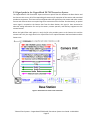
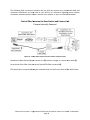
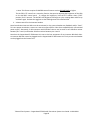
2.3.Signal paths in the CopperHead FS-790 Transceiver System
The CopperHead FS-790 Transceiver System utilizes an optical fiber link between the Base Station and
the Camera Unit to carry all of the required signals necessary for operation of the camera and associated
production equipment. The Camera Unit multiplexes electrical signals from the camera and other remote
sources and converts them to an optical signal for transmission over the fiber. Simultaneously, an optical
return signal is received at the Camera Unit from the Base Station; this signal is then converted to
electrical analog information for use by the camera, camera operator, and auxiliary equipment at the
camera location.
When the hybrid fiber cable option is used, the link also provides power to the Camera Unit and the
camera itself. Only the single fiber link or hybrid fiber link is required between the Base Station and the
Camera Unit.
Figure 4- Base Station to Camera Unit Connection
Telecast Fiber Systems – CopperHead FS790 ProHD Transceiver System User Guide –110124V4JH
Page 15
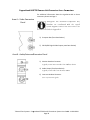
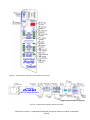
2.4.CopperHead FS-790
790 Transceiver System Components
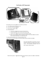
CopperHead KA-F790 Camera Unit Overview
Figure 5 - Camera Unit: Connector Panels
Figure 6 – Camera Unit:
Unit Indicator and
Intercom Level Control Panel
The actual appearance of your CopperHead KA-F790 Camera Unit will vary depending on the battery mount
and fiber cable connection options specified at the time of purchase.
CopperHead RM-FP790 Base Station
-12
Figure 7 - Base Station: Front Indicator Panel
Figure 8 - Base Station: Rear Connector Panel
The actual appearance of your CopperHead R790 Base Station will vary depending on the fiber cable
connection
ion and power options specified at the time of purchase
purchase.
Telecast Fiber Systems – CopperHead FS790 ProHD Transceiver Sys
System
tem User Guide –110124V4JH
Page 16
CopperHead FS-790 Transceiver System Additional Components
In addition to the CopperHead FS-790 Camera Unit and Base Station the system consists of:
1. External Power Supply or Power Cord for the Base Station (depending the unit configuration)
2. Cable Sets as required by your camera and remote controller types to connect the CopperHead
Camera Unit to the camera, and to connect the Base Station to the optional remote controller
3. Hardware kits for rack mounting the Base Station
4. Portable fiber reel with fiber per your purchase order
5. Optional “Power Wafer” Camera Adaptor with optional external power supply
Additional JVC accessories for your camera may have been supplied at the time of purchase.
NOTE: You must use your own cables to make connections for Tally, Black Burst/Gen Lock, Base Station
monitor, and other ancillary signals and equipment. See Appendices 1 & 2 for suggestions.
Telecast Fiber Systems – CopperHead FS790 ProHD Transceiver System User Guide –110124V4JH
Page 17
Page Intentionally Left Blank
Telecast Fiber Systems – CopperHead FS790 ProHD Transceiver System User Guide –110124V4JH
Page 18
Chapter 3. Installation of the CopperHead KA-F790 Camera Unit on the
JVC ProHD GY-HM790 Video Camera
This chapter describes the physical installation of the CopperHead FS-790 Transceiver System. The following
areas are covered:
1) Initial Installation of the CopperHead KA-F790 Camera Unit to the camera
2) Mounting of the optional Power Wafer Unit to the CopperHead FS-790 Camera Unit
3) Relocation of the CopperHead FS-790 Base Station Fiber connector from the back panel to the front
panel
3.1. Initial Installation of the CopperHead KA-F790 Camera Unit to the Camera
This section describes the physical installation of the CopperHead KA-F790 Camera Unit to the camera.
Installation should only be performed by a technically qualified individual. Typically the installation will be
performed by the technical staff at your JVC Dealer, System Integrator or a technician on your organization’s
staff. A qualified and experienced individual should be able to accomplish the installation in about 15
minutes.
The installation encompasses the following steps:
1) Verification of all components
2) Relocation of the Battery Adaptor from the back of the Camera to the KA-F790 Camera Unit
3) Installation of the Camera Unit Mounting Plate on to the camera
4) Installation of the Connector Adaptor Plate and connection of required cables
5) Mounting of the Camera Unit on to the Mounting Plate
6) Operational test of the installed system
You will need a clean flat surface upon which to work and a medium Phillips screwdriver to perform the
installation of the Camera Unit on to the Camera.
This User Guide illustrates the installation of a Camera Unit on to a Camera equipped with an Anton Bauer
type battery. The V-Mount system installation is identical with the very minor wiring connector differences.
Telecast Fiber Systems – CopperHead FS790 ProHD Transceiver System User Guide –110124V4JH
Page 19
Verification of All Components
The following items are required for the installation procedure:
A) The CopperHead KA-F790
F790 Camera Unit
B) The Camera Unit Mounting Plate
C) The Connector Adaptor Plate
D) Screw Assortment
a. 2 Connector Adaptor Plate Screws (with lockwashers)
b. 6 Mounting Plate to Camera Screws (black Phillips Head)
c. 4 Camera Unit to Mounting Plate Screws (plated Phillips head)
d. Note: The screws used to mount the Battery Adaptor to the Camera will be re-used
re
to
mount the Battery Adaptor to the Mounting Plate
E) Optional Power Wafer Unit – for Powered Systems only
Insure that all off these items are present before beginn
beginning
ing the installation procedure.
The Camera described in this section is the GYHM790U equipped with the Anton Bauer battery
mount. The GY-HM790E
HM790E is equipped with the
IDX “V-Mount”
Mount” Battery mount.
Telecast Fiber Systems – CopperHead FS790 ProHD Transceiver Sys
System
tem User Guide –110124V4JH
Page 20
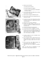
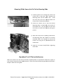
Relocation of the
he Battery Adaptor from the Camera to the KA
KA-F790
F790 Camera Unit
1) Place the camera on a flat surface with the
battery mount towards you
2) Remove each of the four retaining screws
indicated in the illustration
3) Be careful not to strip these screws during
this procedure
rocedure as they will be needed later
4) Place the screws in a safe place where you
can get them in a few minutes
5) Carefully pull the battery mount off of the
camera and lay it wiring side up next to the
camera. Be careful not to stretch any of the
attached wires
ires past their limit
1) Identify the Velcro cable retainer inside the body
of the camera
2) Pull the Velcro tab free and carefully pull the
internal Power Cable connection free of the
camera
Telecast Fiber Systems – CopperHead FS790 ProHD Transceiver Sys
System
tem User Guide –110124V4JH
Page 21
1) Identify three connectors
a.The white power connector
b.The black voltage
ltage data connector
c. The black unused connector (not connected to
the battery adaptor)
2) Pull the white power connector apart by pushing
the connector release tab
3) Slide the black voltage data connector apart
4) Once the two connectors are separated put the
camera to one side
1) Position the Camera Unit on the working surface
so that the connectors are positioned as shown
in the illustration
2) Identify the 4 screw holes as indicated
3) Position the Battery Mount so that you can
access the connectors in the Battery Mount
Mo
and
the Camera Unit
4) Connect (A) the White Power connector
5) Connect (B) the Power Voltage Data Connector
6) Position connector (C) inside the opening of the
Camera Unit to that it will not be pinched by the
Battery Mount when attached to the Camera
Unit. This
his connector is not used.
1) Carefully position the two connected wires
within the Camera Unit
2) Place the Battery Mount on to the Camera Unit
being careful not to pinch any of the wires
between the Battery Mount and the Camera
Unit
3) Line up the four screw holes between the
Battery Mount and the Camera Unit
4) Install the screws you removed in the previous
step
Note: For these steps the installation of the
IDX “V-Mount”
Mount” battery adaptor is identical
Telecast Fiber Systems – CopperHead FS790 ProHD Transceiver Sys
System
tem User Guide –110124V4JH
Page 22
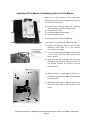
Installation Of The Camera Unit Mounting Plate On To The Camera
Identify the various features of the Camera Unit
Mounting Plate (the camera facing side of the plate
is shown in this illustration)
A) Camera plate mounting hooks (for mounting
into the Camera accessory mounting slots)
B) Connector wire cutout
C) Connector
onnector Adaptor Plate cutout
D) Video Connector Cutout
Six Mounting Plate to Camera screw holes
Four Camera Unit to Mounting Plate screw holes
1) Position the Mounting Plate so that the two
Mounting Plate hooks sit in the Camera
accessory mounting slots
2) Line up the Mounting plate with the screw holes
in the Camera (the same ones used by the
Battery Mount)
3) Make sure that the connectors and wires feed
through the (B) Connector wire cut out and are
not pinched between the Camera and the
Mounting Plate
1) When the
he Plate is seated properly secure it to
the Camera using the provided 4 Chrome plated
flat head screws
2) Before tightening down the Plate confirm that
the wires move freely in the Connector wire
cutout
Telecast Fiber Systems – CopperHead FS790 ProHD Transceiver Sys
System
tem User Guide –110124V4JH
Page 23
Installation Of The Connector Adaptor Plate And Connec
Connection
tion Of Required Cables
1) Position the Connector Adaptor Plate into the
cutout as shown
2) Carefully push the Adaptor Plate onto the
existing 68 pin connector in the Camera
3) Secure the Adaptor plate to the Camera using
the two provided lock washer screws – Do not
over tighten these screws so as to prevent
damage to the Adaptor plate
1) Position the Camera Unit in front of the Camera
and Mounting Plate as shown
2) Position the various connectors so that they do
not interfere with each other
a. White Power Connectors
b. 68 Pin Ribbon Cable
c. HD/SDI Video Cable
3) Position the two unused black voltage and
battery data connectors so that they are out of
the way
1) Connect the two white Power Connectors (A)
2) Carefully seat the 68 pin ribbon cable on to the
Camera Adaptor Plate (B)– line up the connector
key and open the locking levers on either side of
the Camera Adaptor
3) Only slight pressure is needed to firmly connect
the ribbon cable if the key is properly aligned –
once seated the locking levers will snap closed
and secure the connector
4) Connect the HD/SDI Cable (C) to the Camera
video connector through the Video Connector
cut out
Telecast Fiber Systems – CopperHead FS790 ProHD Transceiver Sys
System
tem User Guide –110124V4JH
Page 24
Mounting Of the Camera Unit On To the Mounting Plate
1) Carefully position the various wires within the
Camera Unit so that they “float” between the
Mounting
ounting Plate and the Camera Unit – make
sure that they will not be pinched when the
Camera Unit is attached to the Plate
2) Locate the Camera Unit so that the Camera
Mounting Plate is seated within the interior of
the Camera Unit – you may want to insure that
tha
the Camera is stable and stationary during this
process
1) When the Camera Unit is securely positioned on
the Mounting Plate and all wires are securely
contained within the Camera Unit secure the
Camera Unit using the six provided black flat
head screws
2) Install all six screws loosely before tightening
them down
Operational Test Of The Installed System
When the Camera Unit has been successfully installed perform an Operational Test of the system to
insure that all connections were made properly. Follow the setup and operating procedures described in
Chapters 5 & 6 of this user guide.
Telecast Fiber Systems – CopperHead FS790 ProHD Transceiver Sys
System
tem User Guide –110124V4JH
Page 25
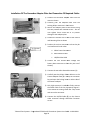
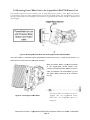
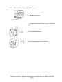
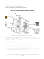
3.2.Mounting
Mounting Power Wafer Unit to the CopperHead KA-F790 Camera Unit
This example illustrates the use of a camera with an Anton
Anton-Bauer battery mount system.
ystem. This case illustrates
a configuration where the camera is powered through the Power Wafer option. The Power Wafer is powered
through a Hybrid fiber cable which is powered from the CopperHead FS-790 Base Station or MPS External
Power Supply.
Figure 9 - Mounting the Power Wafer Unit to the CopperHead FS-790 Camera Unit
The Power Wafer is attached to the CopperHead FS-790 Camera Unit in place of the battery. It is
attached in the same manner as the camera battery.
When the Power Wafer is securely mounted
to the CopperHead FS-790 Camera Unit
connect the supplied Power Wafer connector
cable (1) between the Power Wafer (2)
( and
the Power Wafer connector on the Camera
Unit (3)
Figure 10 - Connecting the Power Wafer
The Power Wafer to Camera Unit cable is
supplied with the CopperHead Power
Wafer Unit For configuration please see
Chapter 5.
Telecast Fiber Systems – CopperHead FS790 ProHD Transceiver Sys
System
tem User Guide –110124V4JH
Page 26
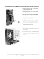
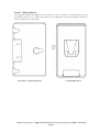
3.3.Relocation of the CopperHead RM-FP790 Base Station fiber connector
The CopperHead RM-FP790 Base Station may be configured with the fiber connector mounted either on the
back or the front of the Base Station. You may order your Base Station in either configuration and it is
possible to relocate the Fiber Connector from one position to the other in the field.
Figure 11 - CopperHead RM-FP790 Base Station with Rear Mounted Fiber Connector
Figure 12 - CopperHead RM-FP790 Base Station with Front Mounted Fiber Connector
The Fiber Connector relocation process ccan
an be accomplished by a qualified Telecast Fiber technician in about
15 minutes or less. You should give yourself an hour with the expectation that it will take less time.
For a complete illustrated step-by--step procedure please go to http://www.telecast--fiber.com/support and
click on the CopperHead FS-790 Technical Notes link or contact Telecast Fiber System support directly.
Telecast Fiber Systems – CopperHead FS790 ProHD Transceiver Sys
System
tem User Guide –110124V4JH
Page 27
Page Intentionally Left Blank
Telecast Fiber Systems – CopperHead FS790 ProHD Transceiver System User Guide –110124V4JH
Page 28
Chapter 4.
CopperHead FS-790 Transceiver System Detailed
Det
Description
This chapter describes in detail each element on the Camera Unit and Base Station of the CopperHead FS-790
Transceiver System. Physical configuration of the system and system connections and practical operation are
covered in following chapters. For an overall view of component location please see the CopperHead FS-790
Transceiver System overall diagrams in Appendix 4.
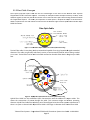
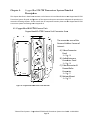
4.1. CopperHead KA-F790
790 Camera Unit
CopperHead KA-F790 Camera Unit Connector Area
The connector area of the
Camera Unit has 4 areas of
interest:
A) Video Connector
Panel
See Page 30
B) Audio/Intercom
Connector Panel
See Page 30
C) Fiber Connector &
Power Wafer
Connector
See Page 31
D) Battery Mount
See Page 32
Figure 13 - CopperHead FS-790
790 Camera Unit Back Side
Telecast Fiber Systems – CopperHead FS790 ProHD Transceiver Sys
System
tem User Guide –110124V4JH
Page 29
CopperHead KA-FF790 Camera Unit Connector Area –Connectors
Connectors
For additional information about the signals carried on these
connectors please see Page 4.
Area A – Video Connector
Panel
Throughout this document component Key
Numbers are coordinated with
w
the overall
system diagrams found at the end of this User
Guide in Appendix 4.
3) Prompter Out (from Base Station)
5) SD-HD/SDI Digital Video Output (from Base Station)
Area B - Audio/Intercom Connector Panel
2) Monitor Headset Connector
Typically return intercom audio from the Base Station
4) Audio Output (from Base Station)
Typically return audio from the Base Station
6) Intercom Headset Connector
Two way intercom signals
Telecast Fiber Systems – CopperHead FS790 ProHD Transceiver Sys
System
tem User Guide –110124V4JH
Page 30
Area C - Fiber Connector & Power Wafer Connector
7) Fiber Cable Camera Connector
8) Power Wafer Connector
The CopperHead KA-F790 Camera Unit is shipped with
one of the two Fiber Connectors shown below.
15 A) SMPTE 304M (powered)
15 B) OpticalCON (powered or unpowered)
Telecast Fiber Systems – CopperHead FS790 ProHD Transceiver Sys
System
tem User Guide –110124V4JH
Page 31
Area D – Battery Mount
The CopperHead KA-F790 Camera Uni
Unit is fitted for one of two of Battery to camera mount types: the
Anton Bauer mount or the V-mount.
mount. The battery mount shipped with the camera is reused as the battery
mount installed on the Camera Unit.
Anton-Bauer
Bauer Type Battery Mount
V-type
type Battery Mount
M
Telecast Fiber Systems – CopperHead FS790 ProHD Transceiver Sys
System
tem User Guide –110124V4JH
Page 32
CopperHead KA--F790 Camera Unit Indicator and Control Panel
The CopperHead KA-F790 Camera Unit Indicator Panel has a series of LED displays that
monitor the various signal paths between the Camera Unit and the Base Station.
For signals remain constantt such as time code and video the LED remains on as a steady green.
For signals that fluctuate such as audio
audio, the LED will reflect the varying signal activity...
activity
If the LED is off either the signal has been lost or it is not in use.
Please see the Overview Diagram in Appendix 4
The LED indicators on the left side of the
panel indicate signal paths from the
Camera Unit to the Base Station
Station.
Right side LEDs indicate signal paths from the
Base Station to the Camera Unit.
1) Intercom Control Group
Intercom Talk active indicator controlled by switch
Please see Section 6.4 for information on use of the Intercom
Control Group
2) Intercom Headset Level Control
3) Tally Indicator Light
Indicates the status of the GPI/Tally 1 signal
Off when the signal is not present
Bright Red when the signal is present
4) SDI Digital Video Signal
Monitors camera SDI Video to Base Station and SDI return
video to the Camera Unit
5) Video/Return – Analog Video Signals
Monitors Camera Monitor video from the Camera
Ca
Unit to the
Base Station and Return Video to the Base Station from the
Camera Unit
6) Sync
Monitors Genlock (one way from Base Station to Camera)
7) Prompt
Monitors a Prompter Feed (one way from Base Station to
Camera
Telecast Fiber Systems – CopperHead FS790 ProHD Transceiver Sys
System
tem User Guide –110124V4JH
Page 33
8) AUD 1 & AUD 2 (Program Audio Channels 1-2)
Monitors program audio from Camera Unit to Base Station and
return audio from Base Station to Camera Unit
9) INTCOM
Monitors Intercom activity from Camera Unit to Base Station
and return audio from Base Station to Camera Unit
10) CCU
Monitors camera control unit data in both directions
11) T.C.
Monitors time code from Camera Unit to Base Station and time
code from Base Station to Camera Unit
Area D - Optical Link Signal Strength Indicator & Power Switch
12) Optical Link Indicator
Indicates the status of the optical connection from base to
camera and camera to base
Green when both the Base Station and Camera Unit have
optical power within normal range.
Red when either the Base Station or Camera Unit optical
power is not within normal range.
13) Power Indicator LED
Green indicates power is applied to the Camera Unit. When the
camera is powered on so is the KA-FP790 Camera Unit.
Blinking Green indicates a Camera Unit error. Refer to
DIAG display mode for details – Page 64
Telecast Fiber Systems – CopperHead FS790 ProHD Transceiver System User Guide –110124V4JH
Page 34
4.2.CopperHead FS-790
790 Base Station
The CopperHead FS-790 Base Station is available with a number of options. The unit is ordered with a
specified Power Module, Audio/Intercom Module and Fiber Connector. For an overall view of component
location please see the overall diagrams in Appendix 4.
CopperH
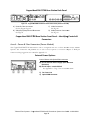
CopperHead FS-790 Base Station Front Panel
Figure 14 - CopperHead FS-790 Base Station Front Panel
A) Optical Connector
See
this Page (Front
Front mounted O
Optional)
B) Audio Indicators
See Page 36
C) Video/Data Indicators
See Page 36
D) Signal Strength Indicators/Setup
See Page 37
E) Status/Power Indicators
See Page 37
CopperHead RM-FP790
790 Base Station Front Panel – Identifying Controls &
Connectors
Area A – Front Panel Optical Connector (Optional)
Blank Panel
Area A of the CopperHead RM-FP790 Base Station provides
for the optional mounting of the Fiber Optical Connector on
the front of the Base Station instead of the rear of the Base
Station.
For information on how to convert the Base Station from Rear
to Front Fiber Connector see Page 27.
Two types of Fiber Connectors are available for use with the CopperHead RM-FP
FP790 Base Station.
One
ne of these Fiber Connectors is pre
pre-configured at the time of delivery.
OpticalCON
SMPTE 304M
Figure 15 - Fiber Connector Types
Telecast Fiber Systems – CopperHead FS790 ProHD Transceiver Sys
System
tem User Guide –110124V4JH
Page 35
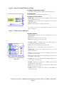
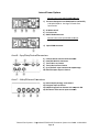
Area B – Audio Indicators
LED Indicators to the left side of the label indicate signal paths
from the Camera Unit to the Base Station and right side LEDs
indicate signal paths from the Base Station to the Camera Unit.
2) Audio Channels 1-2
Monitors Program
rogram audio from Camera Unit to Base Station and
one channel of return audio from Base Station to Camera Unit
3) Intercom
Monitors Intercom audio from Camera Unit to Base Station
and from Base Station to Camera Unit
4) Time Code Signal
Monitors the time code signal generated by the Camera coming
to the Base Station and the Base or House timecode from the
Base Station to the Camera Unit
Area C – Video/Data Indicators
5) SDI Digital Video Signal
Monitors camera SDI video to Base Station
tation and SDI return
video to the Camera Unit
6) Vid/Ret
Monitors Camera analog video from the Camera Unit to the
Base Station and Return analog video to the Camera Unit from
the Base Station
7) Sync
Monitors Genlock signal (one way
ay from Base Station to
Camera)
8) Prompter
Monitors Prompter Feed (one way from Base Station to
Camera)
9) CCU Data
Indicates that two-way
way communication exists between the
Camera Remote Panel and the Camera
10) GPI/Tally Indicators 1-2
Monitors GPI/Tally Signal 1 to Base Station and Camera and
GPI/Tally Signals 1&2 to Camera Unit from Base Station
Telecast Fiber Systems – CopperHead FS790 ProHD Transceiver Sys
System
tem User Guide –110124V4JH
Page 36
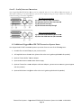
Area D – Signal Strength Indicators/Setup
11) Signal Strength Readout in dBm
This display changes between display modes when selected
12) Select Button
Chooses between three modes of operation
13) Readout Function Indicator
BASE RX – Optical Link signal strength received at Base
Station from Camera Unit
CAM RX – Optical Link signal strength received at Camera
from Base Station
DIAG – Digital display is in Diagnostic mode
For details on how the setup/Diagnostic
gnostic functions operate
please see Page 64.
Area E – Status/Power Indicators
14) Status Indicators
BASE POWER - indicates the status of all power levels in the
Base Station
Green when all power levels are normal.
Red when any power level is not normal.
SYSTEM LOCK - indicates that the Base Station is
communicating with the Camera Unit.
Green when communicating with Camera Unit
Red when it is not communicating with the Camera Unit
FIBER LINK - indicates the optical power status of the Base
Note: Hybrid Power Indicators are
present only on a powered base
station unit
Station and camera
Green when both the Base Station and camera optical power
are within a normal range.
Red when both the Base Station and camera optical power are
not within a normal range
Orange when either the Base Station or camera optical power
are not within a normal range
ALARM - indicates that some error condition exists in either
the Base Station or the camera.
Red if there is a Base Station error. Refer to the Base Station
DIAG for details on the error.
Orange if there is a camera error. Refer to CAM DIAG for
details for the error.
Telecast Fiber Systems – CopperHead FS790 ProHD Transceiver Sys
System
tem User Guide –110124V4JH
Page 37
15) Hybrid Power Indicators
The Hybrid Power indicators are only applicable
a
to units
with the internal power supply (for configurations using the
optional MPS power supply – see Pages 47 & 49).
CAMERA POWER - indicates that high voltage is applied to
power the camera.
Green when high voltage is being supplied to the camera.
Off when there
ere is no high voltage applied to the camera
CABLE OPEN - indicates that the high voltage cable is open
or there is no high voltage cable connected.
Green when the cable is properly connected from the Base
Station to the camera.
Red when there no cable connected
nnected to the camera or the cable
is connected but open.
High voltage will not be applied to the camera until the open
condition is corrected.
Note: Hybrid Power Indicators are
present only on a hybrid power unit
CABLE SHORT - indicates that the high voltage cable
connected is shorted.
16) Power Switch & Power Indicator
Toggle
le switch to enable or disable Base Station power.
LED turns Green when on/off switch is changed to the ON
position.. With a hybrid power system (power supplied by the
Base Station) this switch will control power to the Camera and
the Camera Unit
For the hybrid
ybrid system to be properly powered, the AC Mains
switch on the rear of Base Station must be in the on position.
See next page for details.
Telecast Fiber Systems – CopperHead FS790 ProHD Transceiver Sys
System
tem User Guide –110124V4JH
Page 38
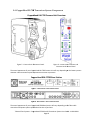
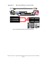
CopperHead RM-FP790 Base Station Back Panel
Figure 16 - CopperHead RM-FP790 Base Station Back Panel (Powered Version)
A) Power & Fiber Connectors
See this Page & Page 40
B) Video/Sync/Data/Control
Sync/Data/Control Connectors
See Page 40
C) Video Connectors
See Page 40
D) Audio/Intercom Connectors
See Page 41
CopperHead RM-FP790
790 Base Station Front Panel – Identifying
ying Controls &
Connectors
Area A – Power & Fiber Connectors (Power Module)
The CopperHead RM-FP790 Base Station can be configured with one of three different Power Module
Options. The connection and practical use of each of these options is covered in Chapter
Ch
5. Multi-pin
connector wiring suggestions are covered in Appendix 1.1.
External Power Options
Internal Power with OpticalCON Connector
19) 12V DC External Power Supply input connector
(XLR 4 Pin)
20) 12V DC Input – terminal block
See Appendix 1 – Page 73 for connection details
2) For Future Use
4) OpticalCON Connector
Telecast Fiber Systems – CopperHead FS790 ProHD Transceiver Sys
System
tem User Guide –110124V4JH
Page 39
Internal Power Options
Internal Power with SMPTE 304MConnector
Connector
1) AC Power Receptacle and 4AMP Dual Fuse Assembly
100-240V 50/60 Hz See Page 72 for the Fuse
Specification
2) AC Mains switch
3) For Future Use
4) SMPTE 304M Connector
Internal Power with OpticalCON Connector
4) OpticalCON Connector
Area B – Sync/Data/Control Connectors
5)
6)
7)
8)
9)
10)
Camera Remote Control Panel Connector
Data/GPI Multi-Pin Connector
Time Code In to Camera
Time Code Out from Camera
Sync/Genlock input connector & Loop through
Video Prompter input to Camera
Area C – Video/Ethernet Connectors
11)
12)
13)
14)
Video Output (Analog) from Camera
Prompter Input to Camera
HD/SDI Program from Camera Unit outputs
output A & B
SDI Return Video source Input to Camera
Telecast Fiber Systems – CopperHead FS790 ProHD Transceiver Sys
System
tem User Guide –110124V4JH
Page 40
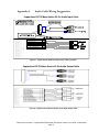
Area D – Audio/Intercom Connectors
The CopperHead RM-FP790 Base Station can be configured with one of two different Intercom Options. A
third option utilizing a Four-Wire
Wire intercom system can be deployed using the 25 pin connectors. Multi-pin
connector wiring is covered in Appendix 2
RTS TW Intercom Module
15) Audio In and Four-Wire Intercom In
16) Audio Out and Four-Wire
Wire Intercom Out
17) RTS TW Intercom Input
18) RTS TW Intercom Loop Through
Clear-Com Intercom Module
17) Clear Com Ch-A Intercom I/O Connector
18) Clear-Com Ch-B intercom I/O Connector
4.3.Additional CopperHead FS-790 Transceiver System Items
Your CopperHead FS-790 Transceiver System may consist of one or more of the following items.
1. Portable fiber reel with fiber
ber per your purchase order
2. JVC Supplied Camera Control Unit (please refer to the User’s guide supplied with this product)
3. Optional “Power Wafer” Camera Adaptor
4. Optional MPS External Power Wafer Power Supply
5. Optional “PowerPlus”” Camera Adaptor and Power Adaptor (please refer to the User’s guide supplied
with this product)
6. Optional HDX Power Unit (please refer to the User’s guide supplied with this product)
Telecast Fiber Systems – CopperHead FS790 ProHD Transceiver Sys
System
tem User Guide –110124V4JH
Page 41
“Power Wafer” Camera Adaptor
The CopperHead KA-FP790 Camera Unit can be powered by the optional “Power Wafer” Camera Adaptor.
The Power Wafer replaces the local camera battery and any local AC power supply adaptor. The Power Wafer
gets its power from the Hybrid fiber cable and the CopperHead FS-790 Base Station equipped with the
internal power supply or from the optional MPS external supply.
Up to 95 watts of power can be delivered to the camera, Camera Unit and camera accessories. Up to 780 feet
(240 meters) of cable can be used when the Camera Unit is powered directly from the Base Station.
The use of an optional external power supply can extend Base Station to Camera range and increase camera
power flexibility. The MPS “Throw Down” Power Adaptor provides this functionality. This unit is described on
Page 44.
The Power Wafer replaces the battery or local
battery mount AC adaptor. Shown with the
Anton/Bauer Battery Mount option.
A short jumper cable carries power from the
Camera Unit to the Power Wafer. The power
comes to the camera on the power section of
the Hybrid Fiber Cable.
Telecast Fiber Systems – CopperHead FS790 ProHD Transceiver System User Guide –110124V4JH
Page 42
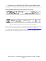
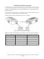
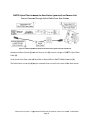
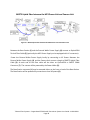
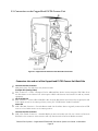
MPS External Power Wafer Power Supply
The CopperHead MPS external power supply provides 95 watts of 12VDC power and fiber cable signal
connectivity from the Base Station to the Camera. From the MPS unit to the camera can be configured
using either a Hybrid OpticalCON connector or a SMPTE 304M connector. The length available is up to
780 feet or 240 meters.
From the MPS unit to the Base Station can be configured using a non-hybrid OpticalCON connector or
two ST connectors. The length available is up to 5 kilometers (3 miles).
The MPS is powered locally with standard AC power. The unit is free standing.
Figure 17 - MPS External Power Wafer Power Supply
All MPS Units require the Power Wafer to provide power to the Camera Unit. Four variations are
available with a different set of fiber cable connectors. All MPS units provide 95 watts of 12VDC power.
Part Number
Fiber Connection to Camera
Fiber Connection to Base Station
CH2-MPS-95VD-2ST-NEU
OpticalCON
2 STs
CH2-MPS-95VD-2ST-304
SMPTE 304M
2 STs
CH2-MPS-95VD-NEU-NEU
OpticalCON (with power)
OpticalCON (no power)
CH2-MPS-95VD-NEU-304
SMPTE 304 (with power)
OpticalCON (no power)
Table 3 - MPS Power Supply Adaptor Options
Telecast Fiber Systems – CopperHead FS790 ProHD Transceiver System User Guide –110124V4JH
Page 43
Page Intentionally Left Blank
Telecast Fiber Systems – CopperHead FS790 ProHD Transceiver System User Guide –110124V4JH
Page 44
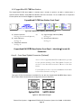
Chapter 5.
Connection of the CopperHead FS-790 Transceiver
System
Prior to connecting your CopperHead FS-790 Transceiver System please insure that each of the required
cables is available for use. This includes standard video, audio and multi-pin cable sets required for your
particular installation. Please see the Appendix for information regarding cables, signals and custom multi-pin
cable fabrication. Covered in this chapter are:
1) Connections between the CopperHead FS-790 Base Station and the Camera Unit (Fiber Cable)
2) Connections between the CopperHead FS-790 Base Station and the base video infrastructure &
power components
3) Connections between the CopperHead FS-790 Camera Unit and external equipment
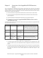
5.1. Connections between the CopperHead RM-FP790 Base Station and the
KA-F790 Camera Unit
The following table summarizes the various Fiber Cable connection options between the CopperHead FS-790
Base Station and the Camera Unit.
Cable Type
Tactical Fiber
Base Station Power
Internal
Camera Unit Power
Local Battery or AC
Power
SMPTE Hybrid
Fiber
SMPTE Hybrid
Fiber
Internal
Power Wafer
Camera Adaptor
Power Wafer
Camera Adaptor
SMPTE Hybrid
Fiber
External – MPS
Power Wafer
Power Supply 95
1
Watts
External – HDX
Power Supply – 150
2
Watts
CopperHead
PowerPlus Camera
Adaptor
Distance Range Between Camera and Base
Up to 10 KM
(This range can be extended to greater than
20 KM through use of the optional High Power
Laser - must be ordered at time of purchase)
240 meters
5 KM between base and MPS power supply
240 meters between power supply and camera
5 KM between base and power supply
3.2 KM between power supply and camera
Table 4 - CopperHead FS-790 Power Options
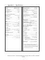
1. The optional external MPS Power Supply must be equipped with the appropriate Fiber Cable
connectors suitable to your system requirements. Please see Pages 43 for a description of the various
options
2. The optional external HDX Power Supply provides two ST Fiber Connectors for connection between
the HDX and the Base Station and a SMPTE 304M Connector for connection between the HDX and
the Camera Unit. Please see the User Guide supplied with the HDX Power Supply for more
information.
Telecast Fiber Systems – CopperHead FS790 ProHD Transceiver System User Guide –110124V4JH
Page 45
The following fiber connection scenarios do not take into account any customized cable and
connector installations you may have at your facility. For assistance regarding more complex
connection situations please contact Telecast Fiber Systems or your local authorized dealer.
Tactical Fiber between the Base Station and Camera Unit
Camera Internally Powered
Figure 18 - Tactical Fiber between the Base Station and Camera Unit
Between the Base Station (1) the Camera Unit (2) connect a length of Tactical Fiber Cable (3).
At each end of the fiber cable
le will be an OpticalCON fiber connector(4).
The Base Station connector (4) may be mounted either on the front or back of the Base Station.
Telecast Fiber Systems – CopperHead FS790 ProHD Transceiver Sys
System
tem User Guide –110124V4JH
Page 46
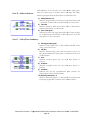
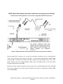
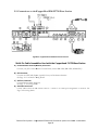
SMPTE Hybrid Fiber between the Base Station (powered) and Camera Unit
Camera Powered through Hybrid Cable from Base Station
Figure 19 - SMPTE Hybrid Fiber between the Base Station (powered) and Camera Unit
Between the Base Station (1) and the Camera Unit (2) connect a length of SMPTE Hybrid Fiber
Cable (3).
At each end of the fiber cable will be either an OpticalCON or SMPTE 304M Connector
Connec (4).
The Base Station connector (4) may be mounted either on the front or back of the Base Station.
Telecast Fiber Systems – CopperHead FS790 ProHD Transceiver Sys
System
tem User Guide –110124V4JH
Page 47
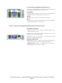
SMPTE Hybrid Fiber between Base Station and Camera Unit (Infrastructure Wiring)
Infrastructure Wiring Built-In to a Facility using OpticalCON Connectors
Figure 20 - SMPTE Hybrid Fiber between Base Station and Camera Unit (Infrastructure Wiring)
Panel mounted fiber connectors can be used for permanent installations such as communications
closets, truck connector panels and sports facilities. A panel mounted OpticalCON or SMPTE 304M
receptacle (4) is connected to the Base Station (1) through infrastructure grade wiring. Two LC Fiber
Optic connectors and four soldered AWG18 copper power wires (3) connect to the Base Station
through an OpticalCON connector(2).
Between the panel mounted receptacle and the Camera Unit is standard Hybrid Fiber Optic cable (5).
This cable is matched to the panel mounted receptacle with either an OpticalCON or SMPTE 304M
connector (4) to (6).
Telecast Fiber Systems – CopperHead FS790 ProHD Transceiver System User Guide –110124V4JH
Page 48
SMPTE Hybrid Fiber between the MPS Power Unit and Camera Unit
Figure 21 - SMPTE Hybrid Fiber between the MPS Power Unit and Camera Unit
Between the Base Station (1) and the External Wafer Power Supply (4) connect an OpticalCON
Tactical Fiber Cable (5) (optionally the MPS Power Supply can be equipped with LC connectors).
Power the External Wafer Power Supply locally by connecting to AC Power. Between the
External Wafer Power Supply (4) and the Camera Unit connect a length of SMPTE Hybrid Fiber
Cable (3). At each end of the fiber cable will be either an OpticalCON or SMPTE 304M
Connector (7). The camera will be powered by the Power Wafer (2).
The Base Station connector (1) may be mounted either on the front or back of the Base Station.
The Base Station will be powered by connection to local AC power (6).
Telecast Fiber Systems – CopperHead FS790 ProHD Transceiver System User Guide –110124V4JH
Page 49
5.2.Connections to the CopperHead RM-FP790 Base Station
Figure 22 - CopperHead FS-790 Base Unit Connections
Multi-Pin Cablee Assemblies Used with the CopperHead FS-790
790 Base Station
A) Camera Remote Control (Remote) Connector
Connector–
Connect your JVC Camera Remote Control Panel (such as RM-LP25, RM-LP55,
LP55, or RM-LP57).
RM
B) GPI Connector
Connect two GPI/Tally Inputs
Inputs, typically from your Production Switcher
See Page 71 for connector wiring details
C) Audio In Connector
Connect Return Audio (line level)
See Page 75 for wiring details
D) Audio Out Connector
Carries audio back from the camera location – connect to an audio processing chain or monitors.
monito See
Page 76 for wiring details
Telecast Fiber Systems – CopperHead FS790 ProHD Transceiver Sys
System
tem User Guide –110124V4JH
Page 50
Connectors into and out of the CopperHead FS-790 Base Station
This information duplicates some of that from above sections. It is presented here to provide a single list of all
Base Station connections. Key numbers refer to the diagram above and to the Overview Diagram found in
Appendix 4.
1 & 19
Power In
Depending on your Base Station model, connect a standard 12V DC ADAP power source (4 Pin) or a
standard 3 conductor AC Cable (IEC Plug) 100-240V 50/60 Hz
4 & 21
Fiber Connector (this connector can be mounted on the Base Station Front Panel – See Page 28)
Connect the fiber connector from either the Fiber Cable connected directly to the camera or to the
MPS or HDX external power supply if your system is so configured. The type of Fiber Connector will
vary depending on your system configuration.
Multi-Pin Connector A
DB9 – 9 pin serial connector connected to an optional Camera Remote Control Panel
5
6
7
8
9
10
Power to the Base Unit must be turned off when connecting the Camera Remote Control
Panel – connecting with the power on can seriously damage your equipment.
Multi-Pin Connector B
DB15 – 15 pin serial connector connected to a breakout of Tally signal connectors. Typically this
connector will be connected to the Camera Tally system originating at the Production Switcher or the
Tally Management system used on your production environment.
See Section 6 for an example configuration.
Time Code In
BNC Connector – Standard time code signal sent to camera – typically originating from “house” time
code generator feed available to Base Station. On remote productions the primary camera may be
used to originate the system time code feed (signal would return to base station via connector 8 and
then be distributed to other cameras through the associated Copperhead Base Stations
Time Code Out
BNC Connector – Standard time code signal originating from the camera. This time code can be used
to reference the local camera time code for proper operations and may also be used as a source for
production wide time code distribution.
Sync In/Loop
BNC Connector – standard Genlock/Sync/Tri-Level sync signal. The loop through is selfterminating.
Video Return (Analog) In
BNC Connector – Typically used to send SD return video to the camera – an example is monitor out
from the Production Switcher
Telecast Fiber Systems – CopperHead FS790 ProHD Transceiver System User Guide –110124V4JH
Page 51
Connectors into and out of the CopperHead FS-790 Base Station
11
12
13
14
15
16
17
&
18
20
Video (Analog) Out
BNC Connector -Typically used for SD Monitoring Video return from the Camera
Prompter In
BNC Connector – SD Video feed from external prompter system originating at Base Station location and
displaying at Camera location
SDI Out A & B (this carries the HD feed from the camera)
BNC Connectors – Two identical video feeds from the camera – typically one may be used for local HD
monitoring and one is fed to the Production Switcher environment.
SDI In
BNC Connector – Typically used to send HD return video to the camera – an example is program out from
the Production Switcher
Audio In- Multi-Pin Connector
DB25 – 25 pin Connector follows the Tascam TDIF standard. The CopperHead FS-790 Transceiver
System accommodates one Audio Channels Line Level. Please see Page 75 for sample wiring.
Audio Out- Multi-Pin Connector
DB25 – 25 pin Connector follows the Tascam TDIF standard. The CopperHead FS-790 Transceiver
System accommodates up to two Audio Channels at Line Level. This connector handles Program audio
from the Camera location. Please see Page 76 for sample wiring.
Intercom Connectors #1 & #2
XLR 3 pin Connectors (Male or Female) depending on configuration. One of two options will be installed
(RTS or Clear-Com).
12V Terminal Block
Terminal Block – bare wire connector. This can be used in place of the ADAP power connection in
installations that have 12V power distributed as part of their infrastructure. Do not use this at the same time
as the ADAP power connection.
Telecast Fiber Systems – CopperHead FS790 ProHD Transceiver System User Guide –110124V4JH
Page 52
5.3. Connections to the CopperHead FS-790 Camera Unit
Figure 23 - CopperHead FS-790 Camera Unit Back Side Connections
Connectors into and out of the CopperHead FS-790 Camera Unit Back Side
2
3
4
5
6
Intercom Headset Connector
Mini-phone Jack – Provides listen only Intercom audio.
Prompter Out (Analog Video)
BNC Connector – Carries a Prompter Feed or additional Base Station return composite VBS Video from
the Base Station to the Camera Unit. This requires a BNC cable between the Camera Unit and any external
equipment.
HD or SD/SDI Out
BNC Connector – Carries HD or SD/SDI video from the Base Station the Camera Unit. Typically this will
feed a digital monitor at the camera position (such as JVC VF-HP790 8.4” Studio Viewfinder.
Audio Out
XLR 3 Pin Male Connector – Provides Return Audio Out from Base Station. Typically connected to an IFB
receiver or local audio monitor at the camera position.
Intercom Headset Connector
XLR 5 Pin Female Connector – Standard RTS-style intercom headset jack. Do not connect an Intercom
Belt Pack to this connector. This connector will only function with an Intercom Headset attached.
Telecast Fiber Systems – CopperHead FS790 ProHD Transceiver System User Guide –110124V4JH
Page 53
7
8
Fiber Connector
Swivel Mounted Fiber Optic Cable receptacle – specific connector depends on your configuration.
Power Wafer Connector
Multi-Pin Connector C – Supplies power to the Camera Unit from the Power Wafer (if so configured). This
cable is supplied with the Power Wafer Power Adaptor.
Telecast Fiber Systems – CopperHead FS790 ProHD Transceiver System User Guide –110124V4JH
Page 54
5.4.Camera Unit Connection Example
Please see the section above for information on these connections.
Camera Unit (Camera Facing Side) to Camera Connections
Figure 24 - Camera Unit (Camera Facing Side) to Camera Connections
Please note that a power adaptor plugged into the Camera Power Connector on the rear of the
GYHM790 Camera will only power the camera and not the KA-FP790 Camera Unit. To power both units you
must supply power through one of the four methods:
1. Battery attached to Camera Unit
2. Power adaptor attached to Camera Unit
3. Power supplied through a Hybrid Fiber Cable by means of a Power Wafer adaptor
4. Power supplied through a Hybrid Fiber Cable by means of a PowerPlus adaptor
It is possible to power the camera directly through the Camera Power Connector and power the camera
unit via the battery plate if the situation calls for this configuration.
Telecast Fiber Systems – CopperHead FS790 ProHD Transceiver System User Guide –110124V4JH
Page 55
Page Intentionally Left Blank
Telecast Fiber Systems – CopperHead FS790 ProHD Transceiver System User Guide –110124V4JH
Page 56
Chapter 6.
Operation of the CopperHead FS-790 Transceiver
System
This chapter describes in detail the operation of CopperHead FS-790 Transceiver System. Please keep in mind
that a wide variety of options and variations are available, so not every possible operational environment can
be described. Variations in battery and powering, fiber cable connections and intercom allow for an
enormous number of slightly different operational modes.
The following topics are covered:
1) Set Up of the CopperHead FS-790 Transceiver System
2) Connecting and Managing the Fiber Cable
3) Connecting the Fiber Cable
4) Powering the System
5) Understanding Intercom usage with the CopperHead FS-790
6) Using the Digital Display
7) Using the Tally System
8) Standard Operation
9) Shutting Down the System
10) Troubleshooting
Telecast Fiber Systems – CopperHead FS790 ProHD Transceiver System User Guide –110124V4JH
Page 57
6.1. Set Up of the CopperHead FS-790 Transceiver System for operation
This section provides an overview of setup of the CopperHead FS-790 Transceiver System for operation. The
following sections provide additional detail on each aspect of setup and operation.
It is important that you do an initial setup and test of your CopperHead FS-790 Transceiver System as soon as
your receive in order to confirm proper operation and to provide training to you and your team prior to an
actual production.
Use the following list of items as an overall checklist for setup.
1. It is highly recommended that you do not attempt to power up the system until all connections are
made and in particular the Fiber Optic Cable has been connected at both ends. If you need to power
up either the CopperHead FS-790 Base Station or Camera Unit make sure that the fiber connectors
are securely capped. This will protect them from damage or dirt and protect you from eye damage.
2. If it is the first time setting up the CopperHead RM-FP790 Base Station or your setup is not
permanent as it would likely be in a remote truck, stadium control room or similar, connect all
required cables. The order in which you connect the cables makes no difference.
a. Make sure to connect the Base Remote cable to the Base Station and Remote Control Panel
when the Base Station power is turned off.
b. Keep Fiber Optic cable connectors capped until actually connecting the Fiber Cable.
3. When setting up the CopperHead KA-FP790 Camera Unit and attached GY-HM790 Camera you will
need to do the following:
a. Setup the external power supply as required. Make sure all cables running between the
CopperHead FS-790 Base Station and the Power Supply and local AC power cords are
properly managed and secured.
b. Connect all required cables according to Chapter 5. The order in which you connect the
cables makes no difference.
c. Set up the Intercom Talk Back switches and level controls as desired. Please see the following
Section 6.4 on Page 63 for details on Intercom operation with the CopperHead KA-FP Series
Camera Unit.
4. Deploy the Fiber Cable (see the next section) – you are now ready to apply power to the system.
Telecast Fiber Systems – CopperHead FS790 ProHD Transceiver System User Guide –110124V4JH
Page 58
6.2.Connecting and Managing the Fiber Cable
Connecting and managing the Fiber Cable between the CopperHead FS-790 Camera Unit and Base Station or
an intermediate power supply requires you to perform four tasks:
1. Plan the route the Fiber Cable will take between the Camera Unit and the Base Station or power
supply
2. Run the Fiber Cable along the planned route
3. Connect the Fiber Cable Connectors at each end
4. Power up the Camera Unit and the Base Station or power supply and check the Fiber Optic Cable Link
and signal strength
Planning the Fiber Cable Route
Obviously the longer the planned cable run the more planning required. It also makes a difference whether
you are running Tactical Fiber Cable or Hybrid Fiber Cable as these affect both the length and the type of
exposure the cable can endure.
When planning your cable route take into the consideration the following:
1. Possible obstacles that might cause you to run short of cable – you may need to take a more indirect,
but achievable route
2. Possible hazards to the cable – while tactical fiber is extremely durable it is not immune to damage.
An obvious hazard is running the cable across a lawn scheduled to be cut during your live production.
Make sure the empty roadway at 6AM will not be filled with heavy equipment when it comes time to
retrieve your cable
3. Possible interference (physical) with the cable that might cause it to bend or kink to an extent that
unacceptable signal loss occurs.
4. Safety hazards – make sure that the cable will not cause a tripping or tangling hazard with people,
animals or vehicles.
5. Decide whether the Fiber Cable is to be unspooled from the Base Station location or the Camera
location. Typically the reel is kept close to the base station. However if there is a chance the Camera
location may need to move further away from the Base Station after initial placement it makes sense
to place the reel at the camera end. Make sure there is enough free cable coming out of the
stationary end of the cable reel to accommodate a well-managed connection to the camera.
Planning the cable route requires common sense and the ability to foresee the unforeseen.
Telecast Fiber Systems – CopperHead FS790 ProHD Transceiver System User Guide –110124V4JH
Page 59
Running the Fiber Cable
Do the following when running your Fiber Cable:
1. Make sure that both ends of the Fiber Cable are securely capped. In this case the concern is dirt and
damage. ANY dirt in the connector can adversely affect Fiber Optical performance and potentially
cause you to lose the use of your camera while the problem is diagnosed and remedied.
2. If the cable run is long or if you will lose sight of the spooling out cable reel make sure you have
appropriate assistance in running out the cable. When retrieving the cable, assistance to prevent the
cable end from being caught or tangled up could be critical. Don’t start reeling in the cable on your
own and assume the Connector end will make it back to home base safely.
3. When unspooling the cable ALWAYS make sure the stationary end (the end that goes to the Base
Station or Power Supply) us securely contained within the reel. A loose Connector can bang around
and be damaged and NEVER connect the stationary end of the Fiber Cable to the Base Station or
Power Supply and the start unspooling the Fiber Cable. Server damage to the cable could occur due
to extreme spiraling of the connected portion of the cable.
Place the stationary cable
connector inside the
center of the reel prior to
unspooling the cable
Telecast Fiber Systems – CopperHead FS790 ProHD Transceiver System User Guide –110124V4JH
Page 60
4. Prior to connecting the Fiber Connectors to the Base Station and Camera Unit inspect both
Connectors. If required, clean with dry compressed air or with technical wipes that have been
moistened with isopropyl alcohol. Fingerprints or other dirt on the optical connector end surfaces
will reduce the optical signal level on the fiber. If the connectors have been properly capped during
storage and movement you will not likely have a problem. However if a connector has been dropped
or dragged through dirt or exposed to dust cleaning is recommended.
5. Once the Fiber Cable has been connected it is time to secure the Fiber Cable run. Make sure there
are no cable hazards in the run. Secure the cable with Cable Guards and/or Gaffers tape to insure
safety.
6. Now the system can be powered on. Plugging in Fiber Cable connectors with the power on will not
damage the system but is not recommended because of the chance of possible eye damage.
7. When re-spooling the Fiber Cable on to the spool guide it across the entire width of the spool so that
it winds evenly and the possibility of cinching or kinks is greatly reduced.
Telecast Fiber Systems – CopperHead FS790 ProHD Transceiver System User Guide –110124V4JH
Page 61
6.3.Powering the System
The CopperHead RM-FP790 Base Station and the CopperHead FS-790 Camera Unit each have a power up
routine which tests the equipment and performs a system diagnostic.
Powering the CopperHead FS-790 Base Station
Base Station Main Power
1.
Base Station Power
2.
Four Character Display
LED Indicator progression
REV display
3.
4.
Scrolling
5.
PAUSE
6.
Diagnostics
7.
Current Status Displayed
8.
Turn on the Base Station Power Mains Switch located at the rear left (when
facing the back of the Base Station) #3 on the overall diagram. This switch is
only on Base Station units with internal power. The front panel power light
will come on and be red until the next step.
Turn on the Front Panel Power Switch located at the front right. #16 on the
overall diagram. The power monitor indicator turns from red to green.
The 4 character display indicates TEST and all front panel LEDs turn, red,
then green, then orange, then off.
The LED color test is followed by REV and the revision of the display
microcontroller firmware.
The REV indication is followed by “telecast-fiber.com” scrolling across the 4
character display. If there's no scrolling please contact Telecast Fiber
Systems support for assistance.
The scroll is followed by about a 3 second interval used to synchronize all
the microcontrollers in the Base Station
The front panel will cycle through the diagnostics displays – See Section 6.5
– Page 65.
After the 3 second pause, all the front panel displays update with current
status. If the Camera Unit is not powered on the camera related status
lights will show red.
Powering the CopperHead FS-790 Camera Unit
Camera Power
1.
LED Indicators On
2.
Turn on the Camera Power and also any peripheral equipment connected to
the camera or the CopperHead KA-FP790 Camera Unit such as monitors and
microphones. Powering up the camera also powers the KA-FP790 Camera
Unit.
On power on the Camera Unit signal and power status indicators will turn
on or flicker according to their current state. Insure that all of these are in
the expected state.
The Base Station has a digital display selector button which allows multiple functions for the digital display.
These functions are described below on Page 65.
Telecast Fiber Systems – CopperHead FS790 ProHD Transceiver System User Guide –110124V4JH
Page 62
6.4. Intercom
The CopperHead FS-790 Transceiver System is delivered with the RM-FP790
FP790 Base Station pre-configured
with either the Clear-Com
Com or RTS “two-wire” intercom options. In addition, the Base Station can be
interfaced to a generic “Four-Wire
Wire” intercom system, using the two 25 pin audio connectors. Multi-pin
connector wiring is covered in Appendix 33.
Figure 25 – Intercom and Tally controls/indicators
Two controls on the KA-7900 Camera Unit provide the following functionality:
1. Push-to-talk (PTT) control for the intercom headset.
This switch provides
rovides momentary/latching operation for the intercom headset microphone.
mic
Momentary Mode:: Press and hold the “TALK” switch, then speak into the microphone. The “TALK”
LED will remain lit while the “TALK” switch is held. Release the “TALK” switch when finished talking.
The “TALK” LED will turn off.
Latching Mode (for Hands-free
free Conversation): Press the “TALK” switch quickly; the mic will open and
the green “TALK” LED will turn on and remain on. When finished talking, press the “TALK” toggle
switch again to close the mic; the “TALK” LED will turn off.
This functionality can be duplicated on the “REC” button on the camcorder’s lens or the pan handle
of the JVC KA-790G
790G Studio Adaptor. To activate this function, go to the camera’s menu screen and
access “Camera function” → “Switch Set Items” → “LENS REC” on the menu and select either “REC”
to set the REC button for traditional “R
“Record Start/Pause” functionality. or to “Intercom” to open and
close the intercom microphone. The default position is “REC” and it can be selected to “INTERCOM”.
See your Camcorder instruction manual for more details.
Telecast Fiber Systems – CopperHead FS790 ProHD Transceiver Sys
System
tem User Guide –110124V4JH
Page 63
Note: This feature requires GY-HM790 camera firmware version SPL2187 V103 or higher.
The KA-790’s PTT control has a secondary function that permits adjusting the brightness of the LEDs
on the KA-790’s control panel. To change the brightness, hold the PTT selector down (“OFF”
position) for 3-5 seconds. The KA-790’s LED brightness will begin to cycle, ramping down and then up
and down again. Release the toggle to set the LED brightness to the desired level.
2. Volume control for the Intercom headset.
Note: Base Station Intercom XLRs must be terminated, or the camera headset may feedback and/or “howl.”
To insure proper termination, connect to a two wire system (RTS or Clear-Com compatible) with a terminated
power supply. Alternately, an XLR connector with 220 Ohm resistors can be used: tie one 220 Ohm resistor
between pins 1 and 2, and another 220 Ohm resistor between pins 1 and 3.
Note that the CopperHead FS-790Camera Unit acts as the last component of any Intercom Belt-Pack chain.
An Intercom Belt Pak cannot be plugged into the CopperHead FS-790 Camera Unit. Only an Intercom headset
can be plugged into the Camera Unit.
Telecast Fiber Systems – CopperHead FS790 ProHD Transceiver System User Guide –110124V4JH
Page 64
6.5.Using the Digital Displays
A Brief Guide to Measurement of Fiber Optic Signal Strength
The CopperHead FS-790 Transceiver System provides direct digital readout of the Fiber Optic Link signal
strength for both the Base Station to Camera Unit Fiber Link and the Camera Unit to Base Station Fiber Link.
This readout is presented in units of dBm. It is useful to understand both the dB or decibel and the dBm or
decibel referenced to one milliwatt.
The decibel (dB) is a logarithmic unit of measurement that expresses the magnitude of a physical quantity
(usually power or intensity) relative to a specified or implied reference level. Since it expresses a ratio of two
quantities with the same unit, it is a dimensionless, relative unit. A decibel is one tenth of a bel, a seldomused unit. Typically dB has been employed in Audio Measurement and Fiber Optics among many uses.
Proper measurement of signal strength requires an absolute measurement and the dBm provides this
measurement. Since it is referenced to the milliwatt, it is an absolute unit, used when measuring absolute
power. By comparison, the decibel (dB) is used for quantifying the ratio between two values, such as signalto-noise ratio
The CopperHead FS-790 Transceiver System operates within a defined range of Fiber Optic Link signal
strength. The minimum recommended signal strength is -22 dBm or better. Typically the system should
operate at levels between -7 dBm and -20 dBm. The standard CopperHead FS-790 laser output strength is -6
dBm. Cable length affects signal strength as does the number of connections between the Camera Unit and
the Base Station. For example, using a Power Supply such as the MPS or HDX adds a minimal signal loss
through each additional fiber optic connection.
The alphanumeric digital display on the CopperHead FS-790 Base Station provides direct signal strength
measurements in dBm. These readouts also provide a wide range of diagnostic information. The use of the
digital display is described below.
The CopperHeadFS-790 Base Station Digital Display
The Base Station digital display has three functions selected by the Display Mode Selector (#14 on the
Overview Diagram). These functions are indicated by the Display Mode LEDs.
1. BASE RX – Base Station Optical Power or Signal Strength that is being generated at the Base Station
and sent to the Camera Unit. Displayed in units of –dBm.
2. CAM RX – Optical Power or Signal Strength generated by the Camera Unit as measured at the Base
Station. Displayed in units of –dBm.
3. DIAG – One of four diagnostics modes available to the Base Station
a. TEMP – displays operating temperature in degrees Centigrade of each circuit board that
reports temperature
b. POWR – displays power level from monitored circuit boards
c. REV – displays microcontroller firmware version from each circuit board with a
microcontroller
d. CAM – displays the error status reported by the Camera Unit
Telecast Fiber Systems – CopperHead FS790 ProHD Transceiver System User Guide –110124V4JH
Page 65
To cycle between Base RX and Cam RX modes, push the Display Mode selector button quickly.
To enter Diagnostic mode, hold the Display Mode selector button for more than 5 seconds. Once in the
Diagnostic mode, a quick push of the selector button cycles through the various diagnostic sub-modes
described above.
The following table describes the expected readouts in each of the above Base Station display modes. By
following the sequence you can understand what the various readouts and four character abbreviations
mean for the system.
Display Mode
Typical
Readout
Base Station Digital Display Activity Explanation
(assumes after initial power up – see Page 66 for a description of the Power Up sequence)
BOPT: Base Station Optical Receive Signal Strength
BASE RX
-9
Indicates that the Base Station received optical signal strength is -9 dBm.
BASE RX
BOPT
Indicates that the Display is showing Base Station optical signal strength.
BASE RX
-9
BASE RX
BOPT
Repeat of the Base Station optical signal strength in dBm.
Repeat that the display is showing Base Station optical signal strength.
This display cycle repeats itself and depending on timing may start with
either BOPT or the strength measurement.
COPT: Camera Unit Optical Receive Signal Strength
CAM RX
COPT
CAM RX
-9
CAM RX
COPT
CAM RX
-9
CAM RX
COPT
Sequence starts with COPT to indicate Camera Unit optical signal strength.
Indicates that the signal strength from the Camera Unit is -9 dBm.
Repeat of the display indicating Camera Unit optical signal strength.
Repeat of the Camera Unit signal strength in dBm.
Repeat that the display is showing Optical link signal strength.
This display cycle repeats itself and depending on timing may start with
either OPT of the strength measurement – COPT does not reappear in the
repeating cycle.
Telecast Fiber Systems – CopperHead FS790 ProHD Transceiver System User Guide –110124V4JH
Page 66
Display Mode
Typical
Readout
DIAG/TEMP
DIAG/TEMP
DIAG/TEMP
DIAG/TEMP
DIAG/TEMP
DIAG/TEMP
DIAG/TEMP
DIAG/TEMP
DIAG/TEMP
TEMP
PS
TEMP
37C
BASE
TEMP
47C
PS
TEMP
DIAG/TEMP
36C
DIAG/POWER
DIAG/POWER
DIAG/POWER
DIAG/POWER
DIAG/POWER
DIAG/POWER
DIAG/POWER
DIAG/POWER
DIAG/POWER
DIAG/POWER
DIAG/POWER
DIAG/POWER
DIAG/POWER
DIAG/POWER
DIAG/POWER
DIAG/POWER
POWR
BASE
POWER
OK
DISP
POWER
OK
CHAR
POWR
OK
AUD
POWR
OK
VBS
POWR
OK
DIAG/POWER
ERR
Base Station Digital Display Activity Explanation
To enter Diagnostic mode, push and hold selector button for 5 seconds.
DIAGNOSTIC MODE Temperature (TEMP)
When first entering the Diagnostic mode, the DIAG display mode indicator
LED will blink – the first sub-mode is TEMP (Temperature). The DIAG LED
will glow Green when the temperature is normal and Red when outside of
normal range.
Indicates the display is in the TEMP sub-mode.
The Power Supply (PS) temperature will be displayed.
Repeats that the display is in the TEMP sub-mode.
Temperature display in Centigrade for Power Supply circuit board.
The Base Station main circuit board temperature will be displayed.
Repeats that the display is in the TEMP sub-mode.
Temperature display in Centigrade for Base Station circuit board.
The Power Supply (PS) temperature will be again displayed.
Repeats that the display is in the TEMP sub-mode.
Temperature display in Centigrade for Power Supply circuit board NOTE:
that the PS temperature has dropped one degree.
This display cycle repeats until the Display Mode Selector is pushed.
DIAGNOSTIC MODE Power Supply Voltage Status (POWER)
A quick push of the Display Mode Selector advances to the Power (POWR)
diagnostic sub-mode. The DIAG LED will glow Green when all power levels
are normal and Red when any power level is outside normal level.
Indicates the display is in the POWER sub-mode.
Indicates that the Base Station main controller board is being measured.
Indicates the display is in the POWER sub-mode.
Indicates that the item is in an OK State.
Indicates that the LED Display controller board is being measured.
Indicates the display is in the POWER sub-mode.
Indicates that the item is in an OK State.
Indicates that the Four Character controller board is being measured.
Indicates the display is in the POWER sub-mode.
Indicates that the item is in an OK State.
Indicates that the Audio controller board is being measured.
Indicates the display is in the POWER sub-mode.
Indicates that the item is in an OK State.
Indicates that the VBS (analog Video) controller board is being measured.
Indicates the display is in the POWER sub-mode.
Indicates that the item is in an OK State.
DIAG/POWER Exception
Instead of OK, the display will show ERR if a power level is outside of
normal – ERR is followed by a Hexadecimal code. Please note the error
code and contact support at Telecast-Fiber.
Telecast Fiber Systems – CopperHead FS790 ProHD Transceiver System User Guide –110124V4JH
Page 67
Display Mode
Readout
DIAG/REV
DIAG/REV
DIAG/REV
DIAG/REV
DIAG/REV
DIAG/REV
DIAG/REV
DIAG/REV
REV
DISP
REV
REVC
VBS
REV
REVA
DIAG/REV
BASE
DIAG/REV
DIAG/REV
DIAG/REV
DIAG/REV
DIAG/REV
REV
REVA
AUD
REV
REVA
DIAG/REV
PS
DIAG/REV
DIAG/REV
REV
REVD
DIAG/CAM
DIAG/CAM
DIAG/CAM
CAM
OK
ERR
Base Station Digital Display Activity Explanation
DIAGNOSTIC MODE Microcontroller Board Revision Version (REV)
A quick push of the Display Mode Selector advances to the Power (POWR)
diagnostic sub-mode. This sub-mode displays the microcontroller firmware
revision of every board in the Base Station that has a microcontroller.
(Note: the REV versions noted here were current as of August 1, 2010. Your
system may have different REV versions)
Initial display of REV after Display Mode Selector being advances.
Indicates the Display microcontroller board is revision is being queried.
Indicates that sub-mode is REV.
Indicates that the REV for the DISP board is REVC.
Indicates the VBS microcontroller board is revision is being queried.
Indicates that sub-mode is REV.
Indicates that the REV for the VBS board is REVA.
Indicates the Base Station main microcontroller board is revision is being
queried.
Indicates that sub-mode is REV.
Indicates that the REV for the BASE board is REVA.
Indicates the audio microcontroller board is revision is being queried.
Indicates that sub-mode is REV.
Indicates that the REV for the AUD board is REVA.
Indicates the power supply microcontroller board is revision is being
queried.
Indicates that sub-mode is REV.
Indicates that the REV for the DISP board is REVD.
This display cycle repeats until the Display Mode Selector is pushed.
DIAGNOSTIC MODE Camera Unit Error Status (CAM)
A quick push of the Display Mode Selector advances to the Camera Unit
(CAM) diagnostic sub-mode. This mode displays the status of the Camera
Unit. The DIAG LED glows green if Camera Unit shows no error and red if
the Camera Unit does have an error.
Indicates that the sub-mode is CAM.
Indicates that the Camera Unit is reporting No fault.
Indicates that the Camera Unit is reporting Some fault.
This display cycle repeats until the Display Mode Selector is pushed.
Telecast Fiber Systems – CopperHead FS790 ProHD Transceiver System User Guide –110124V4JH
Page 68
6.6.Standard Operation
The section is devoted to a number of “Best Practices” for use of the CopperHead FS-790 Transceiver System.
Specific information on how to operate the system has been presented in the sections above.
1. Protect the Fiber Optic Cable and the Fiber Optic Connectors. Always keep these capped unless
there are being connected.
2. Read the section on planning the Fiber Run – it may come in handy – Page 60.
3. Once the system is set up and running, do not ignore the Optical Power Signal Strength Readouts at
either the Camera or the Base Station. While the Alarm functions of the system are very good, so is
the tolerance for optical Signal Strength reduction. By monitoring –dBm levels you can take
preventative action to stop a signal and possibly an On-Air or Recording loss. The system is, of
course, digital and so the Signal Strength is either just good enough or usually much better than that.
When it is no longer strong enough the signal stops.
4. If introducing new equipment (cameras, switchers, etc.) or new operators be sure to do a test run
with everything as it will be during the actual production. Reading this User Guide is a good start but
hands-on is the best way to understand how it will and more importantly what to do to insure proper
operation.
5. If your production is a Multi-Camera shoot with Time Code synchronized between all cameras it is a
good idea to periodically confirm that proper Time Code is being returned from the various cameras
and that a switch has not been changed in error at a camera location.
Telecast Fiber Systems – CopperHead FS790 ProHD Transceiver System User Guide –110124V4JH
Page 69
6.7.Shutting Down the System
System shutdown is simple. The only cautions relate to the Fiber Cable and to the Base Station Remote
Control Panel Cable.
1. To avoid the possibility of looking directly into an active fiber optic port or cable, turn both the
Camera Unit and the Base Station off before disconnecting the fiber from either point.
2. To avoid the possibility of damaging the Camera Remote Control Panel, turn the Base Station off
before disconnecting the Control Cable from the Control Panel or the Base Station.
3. Protect all cables from dirt, water entry and being dragged across the ground or other surface.
4. When re-spooling the cable take your time so as to avoid cable snags, crimps or damage to the
connectors. Re-spool evenly across the reel.
5. If the Base Station is a permanent or semi-permanent installation then simply power off and
disconnect and cap the Fiber Cable.
Telecast Fiber Systems – CopperHead FS790 ProHD Transceiver System User Guide –110124V4JH
Page 70
6.8.Troubleshooting
Troubleshooting any technical issues with the CopperHead FS-790 Transceiver System is similar to any piece
of television production gear with the obvious exception of the core Fiber Optic technology. Here is a list of
things to look out for and check – some of them obvious but sometimes forgotten.
1. Check all your cables – any lost connections or bad connectors?
2. Confirm signal type is on the proper signal path. Though it is possible to physically connect analog
signals to digital signal connectors on the CopperHead FS-790 Transceiver System, signals will not
pass through the system unless they are the correct type. An SDI signal will not pass through the
Analog or VBS paths and an Analog signal will not pass through an SDI path. If the wrong type of
signal is incorrectly connected the signal monitor indicator may light up because an electrical voltage
is present on the line but no signal will pass through.
3. Check your power – are the Power Supplies working?
4. If you are using the PowerWafer and the camera or CopperHead Camera Unit is not powering up,
check the following:
a. The PowerWafer cable is connected to the Camera Unit’s PowerWafer jack.
b. The indicators on the Base Station are all correct (see section 4.2)
c. The fuse on the Base Station is not blown.
5. Take advantage of the various diagnostic tools provided in the CopperHead FS-790 Base Station and
Camera Unit.
a. Is the Fiber Optic Signal Strength within an acceptable range? The product specification calls
for strength of -22 dBm or greater but the system will often work at strengths lower than this
– though not guaranteed to do so – Use the Four Character Digital Display on the Base
Station to check signal strength.
b. Observe all of the LED warning and alarm lights on the Base Station and follow up based on
what you observe.
c. If signal strength is degraded from the time of system checkout at a particular location, walk
the Fiber Cable and see that it is in intact and has no damage of severe bends or kinks.
6. If the digital display indicates an error and displays a Hexadecimal error code you should contact
Telecast Fiber Systems Technical Support to assist in diagnosing the problem. Note the exact error
code so you can report it to the support technician. The hexadecimal errors indicate problems with
the power supplies and the internal boards. In general, field repair is not usually possible if one of
these rare error messages is displayed.
The Digital Display will indicate ERR and then the actual error code will display. This is a typical error
code: 00000010 – this indicates 10 to 16 volt status may be out of range.
Telecast Fiber Systems – CopperHead FS790 ProHD Transceiver System User Guide –110124V4JH
Page 71
Appendices
Appendix 1. Connector Pin Assignments
1.1. CopperHead FS-790 Base Station Connectors
Reference Numbers Refer to the Overview Diagrams in Appendix 4 at the End of this User Guide
Camera Remote
Base Station #5
DB9 Female
Pin
1
2
3
4
5
6
7
8
9
Signal
- Camera Control Data Input
Not Used
Camera Control Data Ground (Shield)
Not Used
- Camera Control Data Output
+ Camera Control Data Input
- 12 VDC Camera Control Data Power Ground
+12 VDC Camera Control Data Power
+ Camera Control Data Output
Table 5 - Base Station Camera Remote Connector Wiring
Tally/GPI Input
Base Station #6
DB15HD Female
Pin
1
2
3
4
5
6
7
8
9
10
11
12
13
14
15
Signal
Not used
Not used
Not used
GPI 1 / Red Tally In
GND
NA
GND
Not used
GPI 2 / Green Tally In
Not used
Not used
Not used
Not used
Not used
Not used
Table 6 - Base Station Tally/GPI Connector Wiring
This cable is end-user supplied.
GPI Inputs:
On: ...................................TTL Low or Short to GND
Off:................................................TTL High or Open
Telecast Fiber Systems – CopperHead FS790 ProHD Transceiver System User Guide –110124V4JH
Page 72
Base Station Audio Inputs & Outputs
Audio In
#15
Audio Out
#16
Return
Audio 1 In
Not Used
Not Used
Cam Audio
1 Out
Cam Audio
2 Out
Not Used
Not Used
Not Used
DB25 Female
DB25 Pin Number
Hot
Cold
Ground
1
24
12
25
2
10
23
11
3
4
21
7
9
20
22
8
Not Used
5
18
6
19
Not Used
4W
Intercom
In
Not Used
4W
Intercom
Out
6
4
17
5
7
15
3
16
Not Used
Not Used
8
1
14
2
Not Used
Base Station #15 & #16
Channel
Not
Connecte
13
d
Table 7 - Base Station Audio 25 Pin Connector Wiring
Please see Appendix 3, page 77 for suggested wiring configurations
configuration
12VDC Input Power Connector
Connectors – Base Station models RM-FP790T
FP790Txxx
Pin
1
2
3
4
Signal
Ground
Unused
Unused
+ Power 12 VDC
Table 8 - Base Station Power Connector
Base Station #19
XLR4 Male
This matching connector is from either an ADAP-AC-04
04 or a customer-supplied
12VDC power supply
Base Station #20
Terminal block
Table 9 - Base Station 12VDC Terminal Block
This connector is wired in parallel with terminal block (#20
(
below)
Pin Signal
1 Minus Voltage Terminal
2 Plus Voltage Terminal
This connector is wired in parallel with XLR4-Male
Male (#19
(
above)
Telecast Fiber Systems – CopperHead FS790 ProHD Transceiver Sys
System
tem User Guide –110124V4JH
Page 73
AC Power Input Connector
Connector- Base Station models RM-FP790
FP790Pxxx
Panel Mounted AC Power Receptacle: 110/220 VAC
Two 4 amp fuses (5 x 20mm).fuses are in operation at all times
– both the AC Line Hot and the AC Line Neut
Neutral
ral are fused.
Base Station #1
Standard IEC C14 receptacle
Replacement: Littlefuse 218.
Clear-Com Intercom
Pin
1
2
3
Signal
Ground
+ VDC Power
Power
Table 10 - Base Station Clear-Com Intercom Connector
Base Station #17 & 18
XLR3 Female (x2)
RTS Intercom
Pin
1
2
3
Signal
Ground
+ VDC Power & Channel 1 Audio
Channel 2 Audio
Table 11 - Base Station RTS Intercom Connector
onnector
Base Station #17
XLR3 Female
Pin
1
2
3
Signal
Ground
+ VDC Power & Channel 1 Audio
Channel 2 Audio
Table 12 - Base Station RTS Intercom Loop-Thru
Thru Connector
Base Station #18
XLR3 Male
Telecast Fiber Systems – CopperHead FS790 ProHD Transceiver Sys
System
tem User Guide –110124V4JH
Page 74
1.2. CopperHead FS-790
790 Camera Unit Multi-Pin Connectors
Power Wafer Connector
Pin
1
2
3
4
Camera Unit #8
4-pin Lemo
Signal
95VDC +
95 VDC Not Used
Not Used
Table 13 - Camera Unitt Power Wafer Connector
Mating connector: Lemo FGG.0B.304.CLAD42 (right angle)
Camera Headset
Pin
1
2
3
4
5
Camera Unit #6
XLR5 Female
Signal
MIC Ground (shield)
+ MIC Input
- Earphone Output Ground
+ Earphone Output
+ Earphone Output
Table 14 - Camera Unit Headset Connector
(pinout: RTS standard monaural headset)
headset
Audio Out
Pin
Signal
1 Chassis ground (cable shield)
2 Positive
ositive polarity terminal ("hot")
3 Return terminal ("cold")
Camera Unit #4
XLR3 Male
Table 15 - Audio Output
utput connector
Telecast Fiber Systems – CopperHead FS790 ProHD Transceiver Sys
System
tem User Guide –110124V4JH
Page 75
Appendix 2.
Base Station Remote Control Cable
10' ± 0.5" boot-to-boot
5
4
3
2
1
CCU (-) Input
CCU (+) Input
9
8
7
6
to base (from CCU)
to base (from CCU)
CCU (+) Output
CCU (-) Output
from base (to CCU)
6
TX (+) Output
5
TX (-) Output
from base (to CCU)
RX(+) Input
4
3
RX(-) Input
- 12VDC GND
2
1
+ 12VDC
PS/2 6-pin Mini-Din
Socket (Female)
9-pin D Male
1
2
3
4
5
6
7
8
9
CCU (-) Input
CCU Format Select
Ground (CCU shields)
+12VDC Bias (for CCU Format
Select only)
CCU (-) Output
CCU (+) Input or Bi-directional
CCU I/O
12VDC CCU Power - Ground
+12VDC CCU Power
CCU (+) Output
1
2
3
4
5
6
7
8
9
6-pin Mini DIN Female
1
2
3
4
5
6
RM-LP25
SIGNAL GND
REMOTE/LOCAL
(detect of HOST)
SIGNAL GND
SID RX DATA
SID TX DATA
9 VDC IN (+)
RM-LP55
Bring to TTL “LOW” to
control camera
RM-LP57
Figure 26 - CopperHead JVC FP-790 Series Base Station Remote Cable
Telecast Fiber Systems – CopperHead FS790 ProHD Transceiver System User Guide –110124V4JH
Page 76
Appendix 3.
Audio Cable Wiring Suggestions
CopperHead FS-790 Base Station 25-Pin Audio Input Cable
Aud 1 Return In HOT(+)
Aud 1 Return In COLD (-)
24
12
Aud 1 Return In GROUND
25
I'Com 4-WIRE In HOT(+) (CH7)
15
I'Com 4-WIRE In COLD (-) (CH7)
I'Com 4-WIRE In GROUND (CH7)
3
16
2
3
1
XLR3 F
2
3
1
XLR3 F
Figure 27 - CopperHead FP-790 Base Station 25-pin Audio Input Cable
CopperHead FS-790 Base Station 25-Pin Audio Output Cable
Figure 28 - CopperHead FP-790 Base Station 25-pin Audio Output Cable
Telecast Fiber Systems – CopperHead FS790 ProHD Transceiver System User Guide –110124V4JH
Page 77
Appendix 4.
Specifications
Video, Digital (bi-directional)
Interface ......................................... SMPTE 259M, 292M
Data Rate ......................................270 Mb/s or 1.5 Gbits/s
Input Level .....................................800 mV (peak to peak)
Input/output Impedance....................................... 75 Ohms
Output Impedance ............................................... 75 Ohms
Bit-Error Rate (@ -22 dBm)..................................... 10-12
Jitter (pathological data). .......................................< 0.2 UI
Rise/Fall Times .................................................... < 270 ps
Video, Analog (bi-directional)
Interface .............................................RS170, NTSC, PAL
Frequency Response
30 Hz-4.2 MHz.................................................... ±0.15 dB
8MHz ........................................................................-3 dB
Video Signal to Noise Ratio .................................. ≥ 72 dB
Differential Gain ....................................................... < 2%
Differential Phase........................................................ < 1°
Audio
Number of Channels................................................. 1-to-2
Type ....................................................Balanced, line level
Impedance ............................................................ >15K Ω
Maximum Input Level............................................ 24 dBu
Quantization ...........................24 bits, 128x (oversampled)
Sample Rate .........................................................48kS/sec
Frequency Response................. ±0.1 dB, 20 Hz to 20 KHz
Intercom
Number or channels .........................................................1
Interface types (Base)........ RTS, Clear-Com or Four-Wire
Frequency Response............................200 - 18KHz ± 3dB
Max Distortion ..................................................... <= 0.5%
Noise ...................................................................< -60dBu
Max Gain (RTS or Clear-Com) ............................>= 24dB
Min Gain (RTS or Clear-Com)............................<= -45dB
GPI/Tally
Number, Base-to-Camera Unit ......................2 (Green & Red)
Inputs:
On:............................................TTL Low or Short to GND
Off:....................................................... TTL High or Open
Electro-Optical
Operating Wavelengths .....................................1300 nm/
TX Laser output power (std./opt) ............. -6 dBm/0 dBm
RX Sensitivity, HD/SDI .....................................-22 dBm
Fiber Compatibility ..................................... Single Mode
Optical Connector Options - Camera Unit:
Local Power...................................... MX or OpticalCON
Remote Power:
Short Range Power ............................ SMPTE 304M or
.................................................................OpticalCON
Long Range Power .................................SMPTE 304M
Optical Connector Options - Base Station:
Unpowered (Tac fiber) ....................... ST or OpticalCON
Remote Power (Hybrid fiber):
Standard Power.........................................SMPTE 304M,
..................................... OpticalCON, or STs & Molex
see note below
Distance Limit *
Tactical Fiber (Local Power at Camera):
Standard laser ...................... 15db optical loss (≈ 5 km*)
Optional DFB laser ............ 19db optical loss (≈ 30 km*)
SMPTE 311M Hybrid Fiber:
Standard Internal Power Supply w/PowerWafer
.............................. ≈ 240m (787 ft): 95W @ 12VDC*
Long Range: HDX w/PowerPlus
................. ≈2km (6562 ft.): 100W Cont./150W Peak*
Mechanical/Environmental
Dimensions (WxLxD)
Camera Unit..................................... 2.5" x 6.5" x 2.2"
Base Station .................................... 17.5" x 9" x 1.75"
Power Wafer ..................................... 5" x 6.12" x 2.2"
PowerPlus LP (100W) ........................... 5" x 6" x 2.5"
PowerPlus HP (150W) ........................... 5" x 6" x 3.7"
HDX.................................................. 13" x 3.5" x 8.5"
Weight
Camera Unit.......................................................1.5 lb.
Base Station .......................................................5.0 lb.
PowerWafer .......................................................1.5 lb.
PowerPlus ............................ LP: 2.3 lb.......HP: 2.5 lb.
HDX.................................................................10.5 lb.
Power Consumption
Camera unit................................. 8 watts@10-18VDC
Base Station (Tac Fiber): .......... 10 watts@10-18VDC
Power Connector.................................... 4-Pin XLR
Base Station (Hybrid Fiber):
Power Req........110-120/220-240 VAC, 50 to 60Hz
Power Consumption....... 250 watts max @120VAC
Temperature Range ..................................... -25° to +55°C
Humidity Range ................. 0 to 95% RH, Noncondensing
* The maximum cable length varies due to optical loss that can
depend on cable quality, dirt/dust/contamination on
connectors, and the number of cable connectors. When using
hybrid cable for camera power, the size of the hybrid cable,
as well as the power draw of the camera, lens, viewfinder,
and other accessories are also factors.
Telecast Fiber Systems – CopperHead FS790 ProHD Transceiver System User Guide –110124V4JH
Page 78
Appendix 5.
Declaration of Conformity
Telecast Fiber Systems – CopperHead FS790 ProHD Transceiver System User Guide –110124V4JH
Page 79
Page Intentionally Left Blank
Telecast Fiber Systems – CopperHead FS790 ProHD Transceiver System User Guide –110124V4JH
Page 80
Appendix 6. CopperHead FS-790 System Overview Diagrams
Figure 29 - CopperHead FS-790 Base Station Rear Panel
Figure 30 - CopperHead FS-790 Camera Unit Connectors
Telecast Fiber Systems – CopperHead FS790 ProHD Transceiver System User Guide –110124V4JH
Page 81
Page Intentionally Left Blank
Telecast Fiber Systems – CopperHead FS790 ProHD Transceiver System User Guide –110124V4JH
Page 82
Figure 31 - CopperHead FS-790 Camera Unit Indicators and Controls
*Appears only on Powered Systems
Figure 32 - CopperHead FS-790 Base Station Front Panel
Telecast Fiber Systems – CopperHead FS790 ProHD Transceiver System User Guide –110124V4JH
Page 83
Telecast Fiber Systems
CH FS790
110124V4JH
A Belden Brand
ww.telecast-fiber.com
©2011