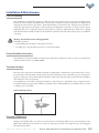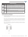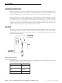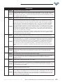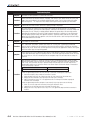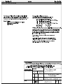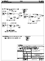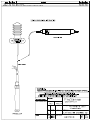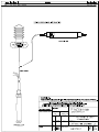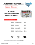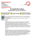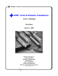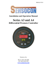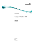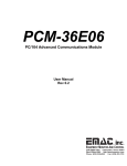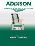
1
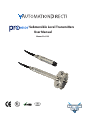
Submersible Level Transmitters
User Manual
Manual 1st. Ed.
~ WARNING ~
Thank you for purchasing automation equipment from Automationdirect.com™, doing business as AutomationDirect. We want your new automation equipment
to operate safely. Anyone who installs or uses this equipment should read this publication (and any other relevant publications) before installing or operating the
equipment.
To minimize the risk of potential safety problems, you should follow all applicable local and national codes that regulate the installation and operation of your
equipment. These codes vary from area to area and usually change with time. It is your responsibility to determine which codes should be followed, and to verify
that the equipment, installation, and operation is in compliance with the latest revision of these codes.
At a minimum, you should follow all applicable sections of the National Fire Code, National Electrical Code, and the codes of the National Electrical
Manufacturer’s Association (NEMA). There may be local regulatory or government offices that can also help determine which codes and standards are necessary
for safe installation and operation.
Equipment damage or serious injury to personnel can result from the failure to follow all applicable codes and standards. We do not guarantee the products
described in this publication are suitable for your particular application, nor do we assume any responsibility for your product design, installation, or operation.
Our products are not fault-tolerant and are not designed, manufactured or intended for use or resale as on-line control equipment in hazardous environments
requiring fail-safe performance, such as in the operation of nuclear facilities, aircraft navigation or communication systems, air traffic control, direct life support
machines, or weapons systems, in which the failure of the product could lead directly to death, personal injury, or severe physical or environmental damage
(“High Risk Activities”). AutomationDirect specifically disclaims any expressed or implied warranty of fitness for High Risk Activities.
For additional warranty and safety information, see the Terms and Conditions section of our catalog. If you have any questions concerning the installation or
operation of this equipment, or if you need additional information, please call us at 770-844-4200.
This publication is based on information that was available at the time it was printed. At AutomationDirect we constantly strive to improve our products and
services, so we reserve the right to make changes to the products and/or publications at any time without notice and without any obligation. This publication may
also discuss features that may not be available in certain revisions of the product.
Trademarks
This publication may contain references to products produced and/or offered by other companies. The product and company names may be trademarked and are
the sole property of their respective owners. AutomationDirect disclaims any proprietary interest in the marks and names of others.
Copyright 2014, Automationdirect.com™ Incorporated
All Rights Reserved
No part of this manual shall be copied, reproduced, or transmitted in any way without the prior, written consent of Automationdirect.com™ Incorporated.
AutomationDirect retains the exclusive rights to all information included in this document.
~ AVERTISSEMENT ~
Nous vous remercions d’avoir acheté l’équipement d’automatisation de Automationdirect.com™, en faisant des affaires comme AutomationDirect. Nous tenons à
ce que votre nouvel équipement d’automatisation fonctionne en toute sécurité. Toute personne qui installe ou utilise cet équipement doit lire la présente
publication (et toutes les autres publications pertinentes) avant de l’installer ou de l’utiliser.
Afin de réduire au minimum le risque d’éventuels problèmes de sécurité, vous devez respecter tous les codes locaux et nationaux applicables régissant l’installation
et le fonctionnement de votre équipement. Ces codes diffèrent d’une région à l’autre et, habituellement, évoluent au fil du temps. Il vous incombe de déterminer les
codes à respecter et de vous assurer que l’équipement, l’installation et le fonctionnement sont conformes aux exigences de la version la plus récente de ces codes.
Vous devez, à tout le moins, respecter toutes les sections applicables du Code national de prévention des incendies, du Code national de l’électricité et des codes
de la National Electrical Manufacturer’s Association (NEMA). Des organismes de réglementation ou des services gouvernementaux locaux peuvent également vous
aider à déterminer les codes ainsi que les normes à respecter pour assurer une installation et un fonctionnement sûrs.
L’omission de respecter la totalité des codes et des normes applicables peut entraîner des dommages à l’équipement ou causer de graves blessures au personnel.
Nous ne garantissons pas que les produits décrits dans cette publication conviennent à votre application particulière et nous n’assumons aucune responsabilité à
l’égard de la conception, de l’installation ou du fonctionnement de votre produit.
Nos produits ne sont pas insensibles aux défaillances et ne sont ni conçus ni fabriqués pour l’utilisation ou la revente en tant qu’équipement de commande en
ligne dans des environnements dangereux nécessitant une sécurité absolue, par exemple, l’exploitation d’installations nucléaires, les systèmes de navigation
aérienne ou de communication, le contrôle de la circulation aérienne, les équipements de survie ou les systèmes d’armes, pour lesquels la défaillance du
produit peut provoquer la mort, des blessures corporelles ou de graves dommages matériels ou environnementaux («activités à risque élevé»). La société
AutomationDirect nie toute garantie expresse ou implicite d’aptitude à l’emploi en ce qui a trait aux activités à risque élevé.
Pour des renseignements additionnels touchant la garantie et la sécurité, veuillez consulter la section Modalités et conditions de notre documentation. Si vous
avez des questions au sujet de l’installation ou du fonctionnement de cet équipement, ou encore si vous avez besoin de renseignements supplémentaires,
n’hésitez pas à nous téléphoner au 770-844-4200.
Cette publication s’appuie sur l’information qui était disponible au moment de l’impression. À la société AutomationDirect, nous nous efforçons constamment
d’améliorer nos produits et services. C’est pourquoi nous nous réservons le droit d’apporter des modifications aux produits ou aux publications en tout temps,
sans préavis ni quelque obligation que ce soit. La présente publication peut aussi porter sur des caractéristiques susceptibles de ne pas être offertes dans certaines
versions révisées du produit.
Marques de commerce
La présente publication peut contenir des références à des produits fabriqués ou offerts par d’autres entreprises. Les désignations des produits et des entreprises
peuvent être des marques de commerce et appartiennent exclusivement à leurs propriétaires respectifs. AutomationDirect nie tout intérêt dans les autres marques
et désignations.
Copyright 2014, Automationdirect.com™ Incorporated
Tous droits réservés
Nulle partie de ce manuel ne doit être copiée, reproduite ou transmise de quelque façon que ce soit sans le consentement préalable écrit de la société
Automationdirect.com™ Incorporated. AutomationDirect conserve les droits exclusifs à l’égard de tous les renseignements contenus dans le présent document.
2
ProSense Submersible Float Level Transmitters User Manual, 1st Ed.
1-800-633-0405
ProSense Submersible Level Sensors Manual
Please include the Manual Name and the Manual Issue, both shown below, when
communicating with Technical Support regarding this publication.
Manual Name: ProSense Submersible Level Transmitters
Issue: 1st Edition
Issue Date: 07/14
Publication History
Issue
Date
Description of Changes
1st Edition
07/14
Original
www.automationdirect.com
ProSense Submersible Float Level Transmitters User Manual, 1st Ed.
3
Notes:
4
ProSense Submersible Float Level Transmitters User Manual, 1st Ed.
1-800-633-0405
Table of Contents
Chapter 1: Product Introduction
Product Description.................................................................................................... 1-2
Features....................................................................................................................... 1-2
Applications................................................................................................................ 1-2
Approvals ................................................................................................................... 1-3
Chapter 2: Installation & Maintenance
Care & Handling......................................................................................................... 2-2
General Installation Procedures................................................................................. 2-2
Transmitter Anchors................................................................................................... 2-2
Transmitter Submersion............................................................................................. 2-2
Vent Filter (Desiccant) or Aneroid Bellow Installation.............................................. 2-3
Polyurethane Jacketed Cable..................................................................................... 2-3
Cable Protection......................................................................................................... 2-4
Bending of Cable........................................................................................................ 2-5
Cable Compression..................................................................................................... 2-5
4-20mA Wiring............................................................................................................ 2-5
Maximum Cable Lengths and Minimum Supply Voltage......................................... 2-5
Protective Cage Diaphragm Protector....................................................................... 2-6
Position Sensitivity..................................................................................................... 2-6
Vent Filter (Desiccant) Maintenance......................................................................... 2-6
Clogged Nose Cap or Dirty Diaphragm.................................................................... 2-6
Cleaning your Transmitter......................................................................................... 2-7
Chapter 3: Product Accessories
Nose Caps & Protective Cage.................................................................................... 3-2
Vent Filter (Desiccant) or Aneroid Bellows............................................................... 3-2
Chapter 4: FAQ’s & Troubleshooting
Frequently Asked Questions....................................................................................... 4-2
www.automationdirect.com
ProSense Submersible Float Level Transmitters User Manual, 1st Ed.
i
Transmitter Field Checks & Troubleshooting............................................................ 4-3
Case Check.................................................................................................................. 4-4
Further Measurements............................................................................................... 4-4
Troubleshooting......................................................................................................... 4-5
Chapter 5: Certifications & Drawings
Product Certifications & Drawings............................................................................ 5-2
Chapter 6: Product Warranty
Product Warranty Statement..................................................................................... 6-2
ii
ProSense Submersible Float Level Transmitters User Manual, 1st Ed.
1-800-633-0405
Product Introduction
In This Chapter...
Chapter
1
2
Product Description.................................................................................................... 1-2
Features....................................................................................................................... 1-2
Applications................................................................................................................ 1-2
Approvals ................................................................................................................... 1-3
www.automationdirect.com
ProSense Submersible Float Level Transmitters User Manual, 1st Ed.
1-1
Product Introduction
Product Description
The ProSense SLT series submersible level sensors provide continuous liquid level measurement by sensing the
hydrostatic pressure produced by the height of liquid above the sensor and providing a 4-20 mA output signal
compatible with PLC’s, panel meters, data loggers, and other electronic equipment. The shielded cable with
atmospheric vent tube and a tough polyurethane jacket incorporating an exclusive “water block” liner beneath the
jacket is attached to the sensor using an over-molding process that prevents moisture intrusion. The SLT1 series has
a slim 1-inch diameter housing and a ported bullet nose cap for protection of the sensor diaphragm. The SLT2 series
features a large 2.75 inch diameter PTFE flexible diaphragm surrounded by a 316 stainless steel non-fouling protective
cage. Accessories include a desiccant vent filter, aneroid bellows, junction boxes, and replacement nose caps.
Features
• Models with ported nose cap or non-fouling cage for diaphragm protection
• Durable 316 SS construction for reliable, long life in harsh environments
• Shielded cable with atmospheric vent; over-molded to prevent moisture intrusion
• 1/2 inch NPT male threaded conduit connection on the sensor housing standard
• Pre-calibrated ranges up to 50 psig (115.3 ftWC) to meet the most common submersible level applications
• +/-0.25% accuracy standard
• All sensors include UL and FM hazardous location approvals for intrinsically safe applications and are CE marked
• Made in the USA
Applications
1-2
• Lift station monitoring
• Tank liquid level
• Landfill leachate monitoring
• Construction by-pass pumping
• Dewatering
• Pump control
• Slurry tank liquid level
• Wastewater
ProSense Submersible Float Level Transmitters User Manual, 1st Ed.
1-800-633-0405
Approvals
UL and FM certification for intrinsic safety options are standard for ProSense SLT series transmitters. Their
respective installation control drawings can be found in Chapter 5. All products are CE compliant to
EN 61326-1:2006 and EN 61326-2-3:2006 and labeled accordingly.
These units are designed for installation in a Class I, Division 1, Groups A, B, C, and D, Class II, Division 1, Groups
E, F and G, Class III, Division 1 hazardous location when connected to appropriate Intrinsically Safe barrier as detailed
in the control drawing located in Chapter 5.
www.automationdirect.com
ProSense Submersible Float Level Transmitters User Manual, 1st Ed.
1-3
Installation &
Maintenance
Chapter
In This Chapter...
2
Care & Handling......................................................................................................... 2-2
General Installation Procedures................................................................................. 2-2
Transmitter Anchors................................................................................................... 2-2
Transmitter Submersion............................................................................................. 2-2
Vent Filter (Desiccant) or Aneroid Bellow Installation.............................................. 2-3
Polyurethane Jacketed Cable..................................................................................... 2-3
Cable Protection......................................................................................................... 2-4
Bending of Cable........................................................................................................ 2-5
Cable Compression..................................................................................................... 2-5
4-20mA Wiring............................................................................................................ 2-5
Maximum Cable Lengths and Minimum Supply Voltage......................................... 2-5
Protective Cage Diaphragm Protector....................................................................... 2-6
Position Sensitivity..................................................................................................... 2-6
Vent Filter (Desiccant) Maintenance......................................................................... 2-6
Clogged Nose Cap or Dirty Diaphragm.................................................................... 2-6
Cleaning your Transmitter......................................................................................... 2-7
2-1
ProSense Submersible Float Level Transmitters User Manual, 1st Ed.
1-800-633-0405
Installation & Maintenance
Care and Handling
Our transmitters are designed for rugged use. However, they need protection from over pressure and sharp impact.
Penetrate the surface slowly, vertically and only to the depth necessary when lowering a transmitter into a liquid. Avoid
dropping the unit from above the surface. Clean all transmitters as instructed in the “Cleaning Your Transmitter”
section that appears later in this chapter. Direct probing of the diaphragm or attempts to remove protective screens
will damage the sensor, voiding the warranty. The protective covering (or similar protective device) that is shipped
with each transmitter should be attached to the transmitter at all times. It should only be removed prior to installation
or cleaning.
Warning: Potential Electrostatic Charging Hazard
In hazardous locations:
• Avoid building up static charge on the plastic accessories.
• Use damp rag to wipe the plastic accessories to avoid static build up.
General Installation Procedures
The following is important installation and preventive maintenance information. If for any reason you should need
technical assistance, call us at 1-800-633-0405.
Transmitter Anchors
Most users either suspend our submersible transmitters in stilling wells or attach them to rigid conduit. This is done to
prevent damage to the transmitter from shock caused by water turbulence. It is not advisable to tie your transmitter to
a pump or to piping, as any problem with the transmitter could require that the pump be pulled from the installation.
This could prove to be very expensive.
Some applications use a bracket to clamp the transmitter to a fixed object (i.e., wall, ladder, step) or require the unit to
be suspended without any protective still well or attachment device. In all installations, care should be taken to ensure
no damage occurs to the cable.
Cable Anchoring Schemes
Transmitter Submersion
Damage to submersible cable is one of the more common causes of transmitter failure. Lower your transmitter into the
liquid slowly, making sure the cable does not drag over sharp edges and only to the depth necessary. Avoid dropping
the unit from the surface.
www.automationdirect.com
ProSense Submersible Float Level Transmitters User Manual, 1st Ed.
2-2
Vent Filter (Desiccant) or Aneroid Bellows Installation
Always install a vent filter (desiccant) or aneroid bellows immediately after transmitter installation. Failure to use one
or the other could result in premature failure of the transmitter; which would not be covered by warranty. If you use a
vent filter (desiccant), you should establish a regular maintenance schedule. You should change your vent filter when
it is 75% depleted (pink color). Replacement filters are available at a nominal cost. Do not remove the old vent filter
until a new one is available. The most common failure mode of our transmitters is moisture and corrosion damage due
to lack of use or maintenance of the vent filter. A clean vent filter (desiccant) allows air into the desiccant filter and
allows the transmitter to properly vent with changes in barometric pressure.
To install/replace either the aneroid bellows or the vent filter (desiccant), simply unplug the old unit from the vent tube
and plug the 0.062 inch x 1 inch PEEK (Polyetheretherketone) connector tube (supplied with each filter or bellows)
into the vent tube.
Reference Connection Schemes
Submersible Cable Termination
Polyurethane Jacketed Cable
Most installations of our submersible level transmitters connect our polyurethane cable to a junction box. From this
junction box users typically run their own cable to the required instrumentation.
2-3
ProSense Submersible Float Level Transmitters User Manual, 1st Ed.
1-800-633-0405
Polyurethane Jacketed Cable Cont.
Specifications for our standard polyurethane jacketed cable are as follows:
Specifications
Submersible Cable
Min. OD
0.28 in (7.10 mm)
Max OD
0.31 in (7.87 mm)
Conductors
Insulation Conductors
Outer jacket
Shield
Vent Tube
2–22 AWG
Polyurethane
36 gauge spiral tinned copper wire foil shield with drain wire
Polyethylene, 0.060 in ID (1.52 mm)
Cable Pull Strength
200lbs (90kg)
Min. Bend Radius
1 in (25.4 mm)
The submersible level transmitter junction boxes provide a water-resistant enclosure for electrically connecting the
transmitter cable to the user’s system via a terminal strip. The enclosure also provides a convenient location for
terminating the transmitter’s vent tube to a vent filter (included in Part No. SLT-JB1) or an aneroid bellows (included
in Part No. SLT-JB2). The enclosure is constructed of polycarbonate with a clear top incorporating a neoprene seal.
The junction box is rated IP66. Mounting screws are provided. Many users require a compression fitting to secure our
polyurethane jacketed cable as it enters a junction box. Care needs to be taken that you do not over-tighten the fitting
and damage the cable.
The vented cable termination end is specially prepared at the factory to eliminate the potential for moisture
migration. Where the lead wires emerge from under the jacket, there is potting material and a shrink tube
“boot”. Every effort should be made to leave this feature intact. Should the cable be longer than needed for the
installation, it is recommended that the excess length be accommodated in a service loop and that the potted
end of the cable NOT be shortened.
The cable attached to this instrument is specifically engineered for submersible applications. The polyurethane
outer jacket provides long term reliability under most conditions. The cable should be handled carefully, however,
as the jacket may be subject to cutting should it be “raked” over extremely sharp edges. To guard against water
incursion should an inadvertent minor cut occur, we have incorporated an exclusive “water block” feature immediately
beneath the jacket. The cable is fully shielded, with the shield connected to the metal housing at the transmitter end and
terminated in a drain wire at the termination or user end. The shield should always be terminated to a good
earth ground, unless the transmitter is installed in an area where galvanic corrosion is known to be a serious
problem.
Cable Protection
An inexpensive way to protect the cable from damage is to connect an inexpensive flexible 5/8 inch garden hose to the
1/2 inch conduit fitting with an inexpensive female PVC 1/2 inch NPT x 3/4 inch NHT swivel fitting, available at
your local hardware store. These options are not supplied by AutomationDirect.com.
www.automationdirect.com
ProSense Submersible Float Level Transmitters User Manual, 1st Ed.
2-4
Bending of Cable
Our polyurethane jacketed cables are quite flexible. Use care to ensure that when bending the cable to suit your
installation you do not crimp the vent tube inside the cable. Consequently, do not bend the cable more than a radius
of 1 inch.
Cable Compression
Many users require a compression fitting to secure the polyurethane jacketed cable as it enters a junction box. Use care
to not over-tighten the fitting so as to damage the cable.
4-20 mA Wiring
Loop Resistance, RL (Ω)
LOOP RESISTANCE vs.
LOOP POWER SUPPLY
1750
1500
1250
RL max =
(V+) – 9V
20 mA
1000
SLT1 & SLT2 Series Wiring Connection
750
4–20 mA output (22AWG conductors in a shielded cable with vent tube)
500
250
0
Operating
Area
9V
0
10
20
30
+ Excitation
Red
- Excitation
Black
Shield
Drain Wire
Loop Power Supply Voltage
Maximum Cable Lengths and Minimum Supply Voltage
At 25ºC the 22AWG conducting copper wire used in our polyurethane jacketed cable has a resistance of 16.45 ohms
per 1000 feet (304m).
2-5
ProSense Submersible Float Level Transmitters User Manual, 1st Ed.
1-800-633-0405
Maximum Cable Lengths and Minimum Supply Voltage Cont.
Using Ohms Law (E=IR) where E=voltage, I=current and R =resistance, a 20mA signal requires 0.329 volts to drive it
along 1000 feet (304m) of 22AWG copper wire (E=16.45 x 0.020). This drop is seen on both the supply and return
wire for a total loop voltage drop of 0.658 volts.
Connect the cable shield (drain wire) to a good earth ground. This will protect the transmitter from relatively minor
transient voltages. The only exception to this rule is if high rates of electrolytic corrosion have been previously
experienced with grounded submersible devices. In this case it may be better to leave the shield disconnected.
Protective Cage Diaphragm Protector
The ProSense SLT2 comes standard with a field removable diaphragm protector (one-inch or 25mm standoff). The
protective cage diaphragm protector can easily be taken off by removing six (6) fasteners located on the bottom of the
unit.
Position Sensitivity
The transmitter should be installed so that the diaphragm located behind the nose cap is oriented in a vertical position,
otherwise the unit could exhibit an offset.
Vent Filter (Desiccant) Maintenance
Warning: Potential Electrostatic Charging Hazard
In hazardous locations:
• Avoid building up static charge on the plastic accessories.
• Use damp rag to wipe the plastic accessories to avoid static build up.
If you use a vent filter (desiccant), you should establish a regular maintenance schedule. You should change your
vent filter when it is 75% depleted (pink color). Replacement filters are available at a nominal cost from the
AutomationDirect.com. Do not remove the old vent filter until a new one is available.
Clogged Nose Cap or Dirty Diaphragm
Either of these conditions could result in erroneous readings from your transmitter.
Warning: NEVER attempt to clean your transmitter’s nose cap or diaphragm with any object. This could dent
or scar the sensor diaphragm and cause permanent damage to the transmitter.
www.automationdirect.com
ProSense Submersible Float Level Transmitters User Manual, 1st Ed.
2-6
Cleaning your Transmitter
Materials required:
• Personal protection equipment (i.e. safety glasses, chemical resistant gloves)
• 3 Plastic bowls 8-12 inches (200-300 mm) in diameter and 4-6 inches (100 - 150 mm) deep
• Supply of clean, lint-free cleaning rags
• Mild dishwashing detergent (i.e. Dawn)
• 16 ounces Tub & shower cleaner (i.e. The Works)
• 3-4 gallons of clean fresh water
Preparation
• P
rior to cleaning your submersible level transmitter, ensure that all appropriate procedures have been followed to
remove any hazardous materials from the cable and transmitter.
• The vent filter (desiccant) or aneroid bellows must be properly attached.
• T
he cable should be coiled to ensure ease of handling and it must be protected against the possibility of accidental
abrasion and/or penetration of the cable jacket by sharp objects.
• A
lead length of 1 to 1 ½ feet (0.3 - 0.45 m) of cable from the transmitter should be allowed to facilitate handling
during cleaning.
Your work surface needs to be clean and free of clutter and large enough to accommodate all materials required in
addition to the transmitter and cable. Fill one of the bowls with fresh water, one with a mild dishwashing detergent
mixed with water and the last with 16 ounces (0.45 kg) of a tub & shower cleaner.
Cleaning Steps
Step 1: Holding the cable 6 inches (150mm) from the transmitter, immerse the unit in the bowl containing the mild
dishwashing/water solution detergent and stir for 20-30 seconds. Remove and rinse in the bowl containing the
fresh water, using the same stirring motion used in the detergent solution. Rinse and wipe dry.
Step 2: Holding the body of the transmitter with one hand so that you are looking at the retaining screen protecting
the sensor, carefully remove the sensor nose cap by simply unscrewing it from the transmitter body. Do not
touch the sensor diaphragm with your finger or any other object. Also, do not try to dry the inside portion of
the transmitter, as you risk damaging the pressure sensor.
Step 3: Place the transmitter in a vertical position with the sensing end facing downward in the bowl containing a tub
& shower cleaner for approximately 15-20 seconds. Rinse in the bowl containing clean water and wipe dry the
external casing only. Place the protective nose cap in the same solution for 15- 20 seconds, rinse and wipe dry.
Step 4: Holding the transmitter in a vertical position so that you can see the face of the sensor, screw the protective
nose cap back into place.
2-7
ProSense Submersible Float Level Transmitters User Manual, 1st Ed.
1-800-633-0405
Product Accessories
In This Chapter...
Chapter
3
Nose Caps & Protective Cage.................................................................................... 3-2
Vent Filter (Desiccant) or Aneroid Bellows............................................................... 3-2
www.automationdirect.com
ProSense Submersible Float Level Transmitters User Manual, 1st Ed.
3-1
Product Accessories
Warning: Potential Electrostatic Charging Hazard
In hazardous locations:
• Avoid building up static charge on the plastic accessories.
• Use damp rag to wipe the plastic accessories to avoid static build up.
Nose Caps & Protective Cage
There are sensor protection options for the ProSense submersible level product line.
• T
he SLT1 series features a ported polyoxymethylene (POM) nose cap with #8-32UNC-2B threaded-hole where
weight accessories can be attached.
Warning: Use caution when inserting a screw into the nose cap as the maximum insertion length should not
exceed 0.175 in.
• The SLT2 features a wide mouth non-fouling cage protecting a 2.75 in PTFE flexible diaphragm.
Vent Filter (Desiccant) or Aneroid Bellows
All submersible level transmitters with molded cable attachment require an optional protective barrier that guards
against moisture buildup in the cable vent tube. These barriers ensure reliable operation and long life as they protect
sensitive electronic components from mildew and prevent the formation of a liquid column in the vent tube. Any such
liquid column directly affects the instantaneous calibration of the transmitter.
Always install a vent filter (desiccant) or aneroid bellows immediately after transmitter installation. Failure to use one
or the other could result in premature failure of the transmitter; which would not be covered by warranty. If you use a
vent filter (desiccant), you should establish a regular maintenance schedule. You should change your vent filter when
it is 75% depleted (pink color). Replacement filters are available at a nominal cost. Do not remove the old vent filter
until a new one is available. The most common failure mode of our transmitters is moisture and corrosion damage due
to lack of use or maintenance of the vent filter. A clean vent filter (desiccant) allows air into the desiccant filter and
allows the transmitter to properly vent with changes in barometric pressure.
To install/replace either the aneroid bellows or the vent filter (desiccant), simply unplug the old unit from the vent tube
and plug the 0.062 inch x 1 inch PEEK (Polyetheretherketone) connector tube (supplied with each filter or bellows)
into the vent tube.
3-2
ProSense Submersible Float Level Transmitters User Manual, 1st Ed.
1-800-633-0405
Faq’s &
Troubleshooting
Chapter
4
In This Chapter...
Frequently Asked Questions....................................................................................... 4-2
Transmitter Field Checks & Troubleshooting............................................................ 4-3
Case Check.................................................................................................................. 4-4
Further Measurements............................................................................................... 4-4
Troubleshooting......................................................................................................... 4-5
www.automationdirect.com
ProSense Submersible Float Level Transmitters User Manual, 1st Ed.
4-1
Frequently Asked Questions
Question
What installation ideas do you have to help me get rid of electrical noise interfering with the signal?
Answer
We strongly encourage you to secure our cable shield to a good earth ground. Armed with this precaution and
the fact that our transmitters are CE approved for electromagnetic interference, you should have few problems.
Either try to eliminate the source of noise or move the transmitters as far away from it as possible.
Question
The cable on the submersible transmitter always seems to get cut and damaged. What am I doing wrong?
Answer
The cable should not be bent around rough or sharp edges. Always use a cable reel during transport. Where
possible, suspend the unit in a perforated 2 inch (50mm) PVC pipe and thread the cable through protective
conduit to the nearest junction box.
Question
I have an application where the transmitter is frequently damaged by voltage spikes. What can be done to
prevent this?
Answer
At a minimum, make sure the cable shield is connected to an earth ground as near as possible to the
transmitter. A surge protector device (purchased separately) will handle typical spikes that might come in
through the power lines as well as surges that travel through the ground due to nearby lightning strikes.
Question
How much impact shock can your submersible transmitters withstand?
Answer
Our transmitters are not shock tested and the lower pressure ranges can be damaged if dropped from several
feet onto a hard surface like concrete. We recommend that the protective shipping sleeve remain in place until
the unit is installed.
Question
How do I attach your vent filter or aneroid bellows to my cable vent tube?
Answer
The vent filter can be mounted anywhere convenient, preferably out of the weather. It can be mounted in any
position and connects to the cable vent tube via the extension tube with connector tube provided. The aneroid
bellows must be mounted in a way that its movement is not encumbered. It is provided with a mounting base.
Question
Any ideas for preventing marine growth on your submersible transmitters?
Answer
A marine grease is sometimes useful in preventing buildup. Remove the threaded nose cap to facilitate
applying the grease. Take care not to damage the diaphragm when applying the grease and not to trap air
bubbles against the sensing diaphragm
Question
How many measurements can you make before the diaphragm on the sensor fails?
Answer
In normal operation - millions of cycles. We find that sensor failure is rarely due to diaphragm fatigue.
Question
What if the cable is too long? Can I cut it off?
Answer
It is recommended that any excess cable length be accommodated in a service loop and that the cable
NOT be shortened.
1.
2.
3.
4.
5.
6.
7.
8.
4-2
ProSense Submersible Float Level Transmitters User Manual, 1st Ed.
1-800-633-0405
Frequently Asked Questions Cont.
Question
What if the supplied cable is not long enough?
Answer
If longer transmitter cable is needed, terminate the sensor in an SLT-JB1 or SLT-JB2 junction box and
run standard non-vented instrumentation cable between the junction box and the measuring electronics.
Question
Does it make any difference if I mount the transmitter in a vertical or horizontal position?
Answer
Yes. Our units will experience a certain amount of position sensitivity. You should mount it in a vertical
position throughout the measurement cycle. If you lay the transmitter down, the user must realize that an
offset will occur.
Question
What happens when you freeze your transmitter in a column of water?
Answer
Depending on the level range of the unit, over pressure of the unit is possible. In harsh environments
where debris is common and ice shifts, you might expect damage to both the transmitter and cable.
9.
10.
11.
Transmitter Field Checks & Troubleshooting
The following is a field check procedure for Level Transmitters. It is designed to provide the information you need
to isolate problems that may occur when using a transmitter. Do these checks to determine in advance whether the
transmitter is operating properly.
When a problem is encountered with a transmitter, it is helpful to test the transmitter independently from
the rest of the system, thereby establishing where to concentrate the troubleshooting effort. It is important to
determine if the fault lies in the transmitter or the instrument reading the transmitter signal, i.e. digital panel meter,
programmable logic controller, etc. If all of the following transmitter tests deliver normal results, the problem may
be found elsewhere in your system.
Below is a simple hookup diagram for a 4-20 mA transmitter. The diagram above illustrates the attachment of
the meter in series with the black (negative signal) wire of the transmitter using a 12-28 VDC power supply for
transmitter excitation.
www.automationdirect.com
ProSense Submersible Float Level Transmitters User Manual, 1st Ed.
4-3
Transmitter Field Checks Cont.
Batteries are suggested to power the transmitter during testing to eliminate the possibility that line noise is
passing through an improperly filtered, grounded, or damaged installation power supply. Use a handheld digital
multimeter (DMM) capable of reading 4-20 mA of current resolution of at least 0.01 decimal places.
Once your transmitter is correctly configured per one of the diagrams, orient the transmitter in a vertical
position with the pressure port down and then read the zero output on your meter. For a 4-20 mA output, the
zero should be between 3.75 and 4.25 mA. If the transmitter is submersible, you may opt to test the unit’s
response in a container of room temperature water and observe its reaction to liquid pressure. It should return
to the same zero point when removed. If the output is outside of these limits, note the results and continue to
troubleshoot the transmitter per the suggested measurements shown below.
Case Check
These checks are performed to detect internal shorts either in wiring that might have made contact with the
structural components of the transmitter, or from water intrusion that has made its way to the internal circuit
board. In either case, there should be zero (0) voltage output on the case when the tests below are performed and
checked with a digital multimeter.
Further Measurements
The following checks to the wiring should be made using a digital multimeter to insure that all connection wiring
offer the listed resistance levels for proper operation.
4–20 mA
+Excitation (red) to Shield
(drain)
4-4
Should Read
> 2.5 Mohms
-Excitation (black) to Shield
(drain)
> 2.5 Mohms
Shield (drain) to Housing
< 2 ohms
ProSense Submersible Float Level Transmitters User Manual, 1st Ed.
1-800-633-0405
Troubleshooting
1.
2.
3.
4.
5.
Symptom
Transmitter fails to give output of any kind.
Procedure
Isolate the problem to either the transmitter or the power supply/readout. See the Transmitter Field Check
procedures in this section. If it can be determined that the transmitter is no longer operable, remove it
from service for further analysis. If the transmitter output falls within the limits described above, the fault
lies somewhere else in your system.
Symptom
Transmitter has failed and has been removed for analysis.
Procedure
Inspect the cable for physical damage. Cuts in the cable jacket can result in liquid incursion into the
transmitter housing, which can cause permanent damage. Inspect the transmitter housing. It should be
intact and free of corrosion. If the outer surface of the transmitter is pitted, this could be an indication
of galvanic corrosion caused by stray ground currents. If this is the case, the transmitter will probably
require replacement. If the external case exhibits none of these characteristics, carefully unscrew the
nose cap and look into the pressure sensing end of the transmitter. The concentric rings of the sensing
diaphragm should be visible. If they are not, it could be that residue has accumulated on the diaphragm,
preventing it from responding properly to pressure changes. The transmitter can be cleaned by gently
swishing the transmitter back and forth in a bucket of warm, soapy water until the residue softens and
washes off. (See Cleaning Your Transmitter)
Under no circumstances should any object or tool be used to remove residue from the sensing diaphragm
or else permanent damage will be done. If cleaning the diaphragm does not solve the problem, contact
AutomationDirect.com for further information.
Symptom
Transmitter develops a negative offset and gets worse over time (actual level exceeds specified level).
Procedure
This may be a sign that moisture has entered the reference (vent) tube in the cable and is inside the
transmitter housing. This is usually the result of not maintaining the desiccant vent filter or of operating
the transmitter without a desiccant filter or aneroid bellows. If caught early enough, the transmitter can
be saved by coiling the cable and transmitter in a pan and placing it in a heat chamber at 50ºC (122ºF)
for a minimum of 2 hours. Be careful that the heat chamber does not exceed 50ºC (122ºF) or both the
transmitter and the cable can be damaged. Alternatively, suspend both the cable and transmitter in a
vertical position (with vent tube down); overnight to allow water to drain from the transmitter and vent
tube.
Symptom
Transmitter suddenly fails during or just after a nearby lightning event.
Procedure
This failure is usually caused by overvoltage due to ground transients resulting from a direct or indirect
lightning event. These transients can travel distances of a mile or more. The transmitter should be
replaced.
Symptom
Transmitter response to pressure/level input changes becomes sluggish.
Procedure
This is usually a sign that the sensing end of the transmitter has become fouled with residue. The transmitter
must be removed from service and the sensing diaphragm cleaned as described in the Installation &
Maintenance section.
Symptom
Output reading is within limits but “freezes” at one point.
Procedure
In certain environments “crust” may form over the sensing diaphragm, preventing the sensor from
identifying changes in level. Removing the transmitter from service and cleaning it (as described in Item
2) will generally solve the problem.
Symptom
No electrical output from your transmitter
Procedure
Check all electrical connections to ensure they are correct and secure. Double check your power supply
or use a battery (as described previously) to ensure the transmitter is getting power. If all checks OK, the
problem could be a circuit board or the sensor in your transmitter. The most probable cause of this type
of failure is damage to the submersible cable jacket allowing water to leak down the cable and into the
transmitter housing or lightning damage.
6.
7.
www.automationdirect.com
ProSense Submersible Float Level Transmitters User Manual, 1st Ed.
4-5
Troubleshooting Cont.
8.
9.
10.
Symptom
Formation of marine growth on a submersible transmitter.
Procedure
Certain transmitter construction materials, including, 316 stainless steel, attract marine life (snails) and
algae. Clean as described in the Installation & Maintenance section. You can also coat the transmitter
with marine grease. This may be the most effective and inexpensive way to protect your transmitter.
Symptom
Submersible transmitter exhibits corrosion or pitting on body or diaphragm.
Procedure
Dissimilar metals (for example, your transmitter housing and your pump housing) in an electrolytic
environment (fluid in your well) can lead to galvanic corrosion of the metal that is nearer the anodic end
of the galvanic series. Likewise, a voltage potential between the ground wire of the transmitter and the
ground of other equipment in the well can lead to galvanic corrosion. Installation of a sacrificial anode
will help protect your transmitter from galvanic corrosion. Sacrificial anodes made of a zinc alloy that,
being nearer the anodic end of the galvanic series than the 316 stainless steel housing of the transmitter,
will corrode before the transmitter.
Symptom
Transmitter has an offset error.
Procedure
Our submersible transmitters perform best when the sensing end is pointing in a downward
manner. Keep in mind that you can experience offset error due to the position sensitivity or orientation
change of the sensor. Offset errors are more prominent in low pressure applications with the sensing end
of the transmitter lying flat or pointing upward.
Symptom
I have a ProSense SLT series 4-20mA transmitter rated for 5 PSIG attached to a pressure source that is outputting
5 PSIG. With 20VDC being supplied I am getting 19.94 mA. I can’t find the upper range allowance for the sensor, but
this seems low to me. Does this mA reading fall into the acceptable range for the transmitter with the settings I’ve
specified?
When evaluating a transmitter it is sometimes convenient to make some broad generalizations in order to rapidly
determine the condition of the unit. In general, transmitters that output a 4-20 mA DC signal have a 16mA DC span
(20 - 4 = 16). If the transmitters accuracy is reported as being some percentage of its full-scale range, then the
following table could be used in conjunction with the instructional notations to determine whether a more detailed
analysis of data quality is required.
11.
Procedure
4-6
Accuracy Rating
Accuracy in mA DC
0.25% FS
0.05 mA
In order to approximately determine how many milliamps a transmitter should output at a given depth:
1. Determine the depth (in feet) at which the transmitter is installed.
2. Divide the depth value (from step 1) by the transmitter full-scale range (in feet). Record the value.
3. Multiply the value calculated in step 2 by 16 (the transmitter span in milliamps).
4. Add 4 to the product of step 3. This is the approximate value in milliamps that should be output by the
transmitter at its current depth
In order to approximately determine the depth of a transmitter (in feet) using a given value of milliamps:
1. Divide the full-scale range of the transmitter (in feet) by 16. Record this value.
2. Subtract 4 from the milliamp output of the transmitter. Record this value.
3. Multiply the result of step 1 by the result of step 2. This is the approximate depth at which the transmitter is
installed.
ProSense Submersible Float Level Transmitters User Manual, 1st Ed.
1-800-633-0405
Certifications &
Drawings
Chapter
5
In This Chapter...
Product Certifications and Drawings......................................................................... 5-2
www.automationdirect.com
ProSense Submersible Float Level Transmitters User Manual, 1st Ed.
5-1
Chapter
Warranty
6
In This Chapter...
Product Warranty Statement..................................................................................... 6-2
6-1
ProSense Submersible Float Level Transmitters User Manual, 1st Ed.
1-800-633-0405
Product Warranty
ProSense Submersible Level Transmitters carry a one-year warranty against defects in materials and workmanship.
If you have questions about the use of your transmitter contact our Technical Support Team at 1-800-633-0405.
***In the event a warranty claim is necessary Do Not Return Product. Please contact our
Returns Team for instructions:
Phone Number
(800) 633-0405
(770)-889-2858
Email:
[email protected]
www.automationdirect.com
ProSense Submersible Float Level Transmitters User Manual, 1st Ed.
6-2