1
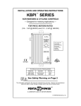
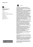
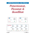
$3RZHU%RRVWHU
Hardware User’s Manual
3ULQFHWRQ $SSOLHG 5HVHDUFK
:$55$17<
PerkinElmer Instruments, Inc. warrants each instrument of its own manufacture to be free of defects in material and
workmanship. Obligations under this Warranty shall be limited to replacing, repairing or giving credit for the purchase
price, at our option, of any instrument returned, shipment prepaid, to our Service Department for that purpose within ONE
year of delivery to the original purchaser, provided prior authorization for such return has been given by an authorized
representative of PerkinElmer Instruments, Inc.
This Warranty shall not apply to any instrument, which our inspection shall disclose to our satisfaction, to have become
defective or unworkable due to abuse, mishandling, misuse, accident, alteration, negligence, improper installation, or
other causes beyond our control. This Warranty shall not apply to any instrument or component not manufactured by
PerkinElmer Instruments, Inc. When products manufactured by others are included in PerkinElmer Instruments, Inc.
equipment, the original manufacturer's warranty is extended to PerkinElmer Instruments, Inc. customers.
PerkinElmer Instruments, Inc. reserves the right to make changes in design at any time without incurring any obligation to
install same on units previously purchased.
THERE ARE NO WARRANTIES THAT EXTEND BEYOND THE DESCRIPTION ON THE FACE HEREOF.
THIS WARRANTY IS IN LIEU OF, AND EXCLUDES ANY AND ALL OTHER WARRANTIES OR
REPRESENTATIONS, EXPRESSED, IMPLIED OR STATUTORY, INCLUDING MERCHANTABILITY AND
FITNESS, AS WELL AS ANY AND ALL OTHER OBLIGATIONS OR LIABILITIES OF PERKINELMER
INSTRUMENTS, INC., INCLUDING, BUT NOT LIMITED TO, SPECIAL OR CONSEQUENTIAL DAMAGES.
NO PERSON, FIRM OR CORPORATION IS AUTHORIZED TO ASSUME FOR PERKINELMER
INSTRUMENTS, INC. ANY ADDITIONAL OBLIGATION OR LIABILITY NOT EXPRESSLY PROVIDED FOR
HEREIN EXCEPT IN WRITING DULY EXECUTED BY AN OFFICER OF PERKINELMER INSTRUMENTS,
INC.
6+28/' <285 (48,30(17 5(48,5( 6(59,&(
A. Contact the Customer Service Department (865-482-4411) or your local representative to discuss the problem. In
many cases it will be possible to expedite servicing by localizing the problem to a particular plug-in circuit board.
B. If it is necessary to send any equipment back for service, we need the following information.
1. Model number and serial number.
5. Your telephone number and extension.
2. Your name (instrument user).
6. Symptoms (in detail, including control settings).
3. Your address.
7. Your purchase order number for repair charges (does not
apply to repairs in warranty).
4. Address to which the instrument should
be returned.
8. Shipping instructions (if you wish to authorize
shipment by any method other than normal surface
transportation.)
C. U.S. CUSTOMERS — Ship the equipment being returned to:
PerkinElmer Instruments
801 S. Illinois Avenue
Oak Ridge, TN 37831
ATTN: Customer Service
PHONE: 865-482-4411
FAX: 865-483-0396
D. CUSTOMERS OUTSIDE OF U.S.A. — To avoid delay in customs clearance of equipment being returned, please
contact the factory or the nearest factory distributor for complete shipping information.
All trademarks used herein are the property of their respective owners.
7$%/( 2) &217(176
1. GENERAL . . . . . . . . . . . . . . . . . . . . . . . . . . . . . . . . . . . . . . . . . . . . . . . 1
2. SYSTEM SPECIFICATIONS . . . . . . . . . . . . . . . . . . . . . . . . . . . . . . . . 3
3. INTERCONNECTIONS . . . . . . . . . . . . . . . . . . . . . . . . . . . . . . . . . . . . 5
3.1. Connecting the Potentiostat to the
Power Booster . . . . . . . . . . . . . . . . . . . . . . . . . . . . . . . . . . . . . . . . 5
3.2. 263A Cell Cable Connections . . . . . . . . . . . . . . . . . . . . . . . . . . . . 7
3.3. KEPCO Front-Panel Setup . . . . . . . . . . . . . . . . . . . . . . . . . . . . . . . 7
3.4. External Cell Connection and Initial Check . . . . . . . . . . . . . . . . . . 7
iii
iv
*(1(5$/
The Model 263A Power Booster is designed for special electrochemical
applications such as battery research, etching, plating, electrosynthesis, and
corrosion studies. Three models are available:
The 263A/10A provides ±10 amps (nominal1) at ±20 volts (nominal)
compliance
The 263A/20A provides ±20 amps (nominal) at ±20 volts (nominal)
compliance
The 263A/8A provides ±8 amps (nominal) at ±50 volts (nominal)
compliance
This add-on system consists of the 263A/94 2A option; a specially configured
20-10A, 20-20A, or 50-8A bipolar power supply from KEPCO®, Inc.; an
internal PerkinElmer Instruments Power Booster Interface (see the block
diagram in Fig. 1); and cabling.
The Power Booster interfaces the 263A and the external cell, acts as the cell
switch, and provides the drive signal for the KEPCO power supply.
Experiments can be controlled manually from the front panel of the 263A or
from a PC using the appropriate PerkinElmer Instruments software.
The Power Booster Interface also provides cell current (scaled) required by
the 263A I/E converter. With the 263A current range set to 10 µA, 1 µA
reading on 263A = 1 A actual cell current; and 10 µA reading on 263A = 10
A actual cell current.
The system frequency response has been modified to provide stability for the
complete closed-loop response for electrochemical cells with a very high
capacitance and very low resistance.
The Power Booster Interface operates in power-boosted or normal mode — a
simple cable connection and flip of a switch convert between modes. This
manual discusses boosted mode only. For normal operation, see the
potentiostat’s user manual.
1
Determined by the KEPCO.
1
Model 263A Power Booster User’s Manual
Fig. 1 Block Diagram for the 263A Power Booster System.
Connections and settings are identical among the three Power Booster
Interface options. However, for simplicity, we discuss and illustrate only the
10-A unit in this manual.
CAUTION Do not use auto-ranging current in Power Booster mode!
The 263A should be set to the 10-µA current range on the
front panel or via PC/software control.
2
6<67(0 63(&,),&$7,216
Bandwidth 5 KHz at 3 db with 1 V applied at counter with 1-6 cell (1-W
load)
Voltage Rise Time <70 µs (10–90%, measured at Counter, ± 10 V/10-Hz
square wave into a 1-W load, high-speed mode).
Potential Noise <500 µV rms at E Monitor Out.
Applied Potential Accuracy ±0.5% of reading, ±2 mV (nominal;
determined by the KEPCO).
Current Measurement Rise Time <75µs (10–90%, measured at I Monitor
Out, ±10 A/10-Hz square wave).
Current Measurement Accuracy ±1% of reading, ± 20 mA.
Rated Output Current 20 A (nominal) for the 263A/20A system; 10 A for
the 263A/10A system; and 8 A (nominal) for the 263A/8A system.
Rated Output Voltage 20 V at 20 A (nominal) for the 263A/20A and
263A/10A; 50 V at 8 A (nominal) for the 263A/8A.
Overload Shutdown ±20 V or ± 20 A (nominal) for the 263A/20A; ±20 V
or ±10 A (nominal) for the 263A/10A; and ±50 V or ±8 A (nominal) for the
263A/8A.2
2
The KEPCO power supply allows you to limit the overload shutdown (that is, to create
shutdown set points at lower than the maximum value. Refer to the KEPCO manual for
more information.)
3
Model 263A Power Booster User’s Manual
4
,17(5&211(&7,216
3.1. Connecting the Potentiostat to the
Power Booster
The 263A and KEPCO are connected by 2 marked cables provided with the
interface unit (see also the diagram in Fig. 2).
CAUTION Make all connections, as well as changes between Normal
and Boost modes, with the power off.
NOTE
Do not use the C0345 cable (the label is on a white tab) in
power-boosted mode. C0345 is for normal operation only (for
instructions on using it, see the 263A User’s Guide).
NOTE
In 4-terminal connections where the sense lead is used, the
263A must be in high-speed mode.
Boost Mode
On the 263A rear panel, flip the BOOST/NORMAL toggle switch to
BOOST.
S-COM Connection
Connect the S-COM brown wire to S COM (or COM; they are shorted
together) on the KEPCO rear panel. Connect the opposite end of the wire
to screw-clamp connector 3 on the rear panel of the Power Booster
Interface.
S-OUT Connection
Connect the S-OUT red wire to S OUT on the KEPCO rear panel.
Connect the opposite end of the wire to screw-clamp connector 4 on the
rear panel of the Power Booster Interface.
5
Model 263A Power Booster User’s Manual
Fig. 2 Connecting the 263A, KEPCO Power Supply, and Power
Booster Interface.
KEPCO Cardedge/Double BNC Cable
Connect the cardedge (female) connector to the card edge (male)
projecting from the KEPCO rear panel (both connectors are keyed to
ensure correct orientation).
On the double-BNC end of the cable, connect the E/IN connector to the
rear panel of the 263A at the BNC connector marked E IN. Connect the
I/OUT BNC portion of the cable to the rear panel of the potentiostat at
the BNC connector marked I OUT.
6
3. INTERCONNECTIONS
3.2. 263A Cell Cable Connections
CO378 Screw Clamp/Spring Clamp Cable
Connect the red and brown leads to the 263A rear panel at screw clamps
1 and 2, respectively (see Fig. 2). The opposite end of this cable
terminates in 2 spring-clamp connectors for the working (brown
wire/green spring clamp) and counter (red wire/red spring clamp) leads.
CO377 LEMO/Spring Clamp Cable (replaces CO345 during boost mode)
Connect this cable to the 263A front panel at the female LEMO
connector. The opposite end of this cable terminates in white and green
spring-clamp connectors for the reference and sense leads, respectively.
3.3. KEPCO Front-Panel Setup
The MODE switch on the front panel of the KEPCO should be set to
Voltage mode (left position).
The Voltage CONTROL switch (red toggle on left side) should be in the
OFF (down) position.
The Current CONTROL switch (red toggle on right side) should be in
the OFF (down) position.
The SENSE/COMMON (black banana jacks at bottom-center) should be
connected with a shorting bracket.
The OUTPUT/SENSE (red banana jacks at bottom-center) should be
connected with a shorting bracket.
3.4. External Cell Connection and Initial Check
Use the provided cell cables (Section 3.2) to connect the electrochemical cell
being tested (see Fig. 3).
7
Model 263A Power Booster User’s Manual
Fig. 3 Connecting the Power Booster Interface to the 263A
Differential Electrometer.
DANGER
Dangerous and possibly lethal voltages may be present
on the electrometer’s red lead. Never touch the red lead
while mains power is supplied to the electrometer. For more
information, see the electrometer manual.
Once the interconnections are complete, perform the following check to
ensure the system is functioning properly:
1.
Connect a 1-6 dummy cell resistor as shown in Fig. 4.
WARNING The dummy cell resistor must have a power rating of at
least 9 W. Three 3-6/3-W resistors linked in parallel are
acceptable.
2.
Connect the Reference and Counter to one side of the resistor
(Reference connection closest to cell), and Sense and Working to the
other side (Sense connection closest to the cell).
3.
Turn on the 263A power.
8
Fig. 4 Dummy Cell Connections.
4.
Turn on the KEPCO power supply.
5.
From the front panel of the 263A, select the 10-µA current range.
6.
Set the 263A to high-speed mode.
7.
Apply a ±3-V potential via the front panel (see the 263A User’s Guide)
and turn the cell on.
8.
The current reading on the front-panel display should be ±3 µA (+3 µA if
3 V are applied), and the E reading should be ±3 V.
9.
Turn the cell off.
10. Turn the 263A and KEPCO power off.
11. Disconnect the cell.
9
3DUW 1R 0DQXDO 5HYLVLRQ $
3ULQWHG LQ 86$