1
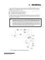
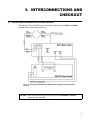
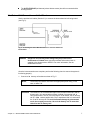
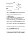
3RZHU%RRVWHU
+DUGZDUH8VHU·V0DQXDO
& 3ULQWHG LQ 86$
$GYDQFHG0HDVXUHPHQW7HFKQRORJ\,QF
a/k/a Princeton Applied Research, a subsidiary of AMETEK®, Inc.
:$55$17<
Princeton Applied Research* warrants each instrument of its own manufacture to be free of defects in material and
workmanship. Obligations under this Warranty shall be limited to replacing, repairing or giving credit for the purchase price, at
our option, of any instrument returned, shipment prepaid, to our Service Department for that purpose within ONE year of
delivery to the original purchaser, provided prior authorization for such return has been given by an authorized representative of
Princeton Applied Research.
This Warranty shall not apply to any instrument, which our inspection shall disclose to our satisfaction, to have become
defective or unworkable due to abuse, mishandling, misuse, accident, alteration, negligence, improper installation, or other
causes beyond our control. This Warranty shall not apply to any instrument or component not manufactured by Princeton
Applied Research. When products manufactured by others are included in Princeton Applied Research equipment, the original
manufacturer's warranty is extended to Princeton Applied Research customers.
Princeton Applied Research reserves the right to make changes in design at any time without incurring any obligation to install
same on units previously purchased.
THERE ARE NO WARRANTIES THAT EXTEND BEYOND THE DESCRIPTION ON THE FACE HEREOF. THIS WARRANTY
IS IN LIEU OF, AND EXCLUDES ANY AND ALL OTHER WARRANTIES OR REPRESENTATIONS, EXPRESSED, IMPLIED
OR STATUTORY, INCLUDING MERCHANTABILITY AND FITNESS, AS WELL AS ANY AND ALL OTHER OBLIGATIONS OR
LIABILITIES OF PRINCETON APPLIED RESEARCH, INCLUDING, BUT NOT LIMITED TO, SPECIAL OR CONSEQUENTIAL
DAMAGES. NO PERSON, FIRM OR CORPORATION IS AUTHORIZED TO ASSUME FOR PRINCETON APPLIED
RESEARCH ANY ADDITIONAL OBLIGATION OR LIABILITY NOT EXPRESSLY PROVIDED FOR HEREIN EXCEPT IN
WRITING DULY EXECUTED BY AN OFFICER OF PRINCETON APPLIED RESEARCH.
6+28/' <285 (48,30(17 5(48,5( 6(59,&(
A. Contact the Customer Service Department (865-482-4411) or your local representative to discuss the problem. In many
cases it will be possible to expedite servicing by localizing the problem.
B. If it is necessary to send any equipment back for service, we need the following information.
1. Model number and serial number.
5. Your telephone number and extension.
2. Your name (instrument user).
6. Symptoms (in detail, including control settings).
3. Your address.
7. Your purchase order number for repair charges (does not apply to
repairs in warranty).
4. Address to which the instrument
should be returned.
8. Shipping instructions (if you wish to authorize shipment by any
method other than normal surface transportation).
C. U.S. CUSTOMERS — Ship the equipment being returned to:
Advanced Measurement Technology, Inc.
801 S. Illinois Avenue
Oak Ridge, TN 37831
ATTN: Customer Service
PHONE: 865-482-4411
FAX: 865-483-2133
D. CUSTOMERS OUTSIDE OF U.S.A. — To avoid delay in customs clearance of equipment being returned, please contact the
factory or the nearest factory distributor for complete shipping information.
Copyright © 2004, Advanced Measurement Technology, Inc. All rights reserved.
*Princeton Applied Research is a registered trademark of Advanced Measurement Technology, Inc. All other trademarks used herein are the
property of their respective owners.
ii
7$%/(2)&217(176
Safety Instructions and Symbols . . . . . . . . . . . . . . . . . . . . . . . . . . . . . . . . . . . . . . . . . . . . . . . . . . . . . . . . . . . . . . iv
Cleaning Instructions . . . . . . . . . . . . . . . . . . . . . . . . . . . . . . . . . . . . . . . . . . . . . . . . . . . . . . . . . . . . . . . . . . . . . . . iv
1. GENERAL . . . . . . . . . . . . . . . . . . . . . . . . . . . . . . . . . . . . . . . . . . . . . . . . . . . . . . . . . . . . . . . . . . . . . . . . . . . . . . 1
2. SYSTEM SPECIFICATIONS . . . . . . . . . . . . . . . . . . . . . . . . . . . . . . . . . . . . . . . . . . . . . . . . . . . . . . . . . . . . . . .
2.1. Overall . . . . . . . . . . . . . . . . . . . . . . . . . . . . . . . . . . . . . . . . . . . . . . . . . . . . . . . . . . . . . . . . . . . . . . . . . . . . .
2.2. Potentiostatic Mode . . . . . . . . . . . . . . . . . . . . . . . . . . . . . . . . . . . . . . . . . . . . . . . . . . . . . . . . . . . . . . . . . .
2.3. Galvanostatic Mode . . . . . . . . . . . . . . . . . . . . . . . . . . . . . . . . . . . . . . . . . . . . . . . . . . . . . . . . . . . . . . . . . .
3
3
3
3
3. INTERCONNECTIONS AND CHECKOUT . . . . . . . . . . . . . . . . . . . . . . . . . . . . . . . . . . . . . . . . . . . . . . . . . . . .
3.1. Connecting the Potentiostat to the Power Booster . . . . . . . . . . . . . . . . . . . . . . . . . . . . . . . . . . . . . . . . . .
3.2. 2273 Cell Cable Connections . . . . . . . . . . . . . . . . . . . . . . . . . . . . . . . . . . . . . . . . . . . . . . . . . . . . . . . . . . .
3.3. KEPCO Front-Panel Setup . . . . . . . . . . . . . . . . . . . . . . . . . . . . . . . . . . . . . . . . . . . . . . . . . . . . . . . . . . . . .
3.4. External Cell Connection and Initial Check . . . . . . . . . . . . . . . . . . . . . . . . . . . . . . . . . . . . . . . . . . . . . . . .
5
5
6
6
7
iii
6DIHW\,QVWUXFWLRQVDQG6\PEROV
This manual contains up to three levels of safety instructions that must be observed in order to avoid personal
injury and/or damage to equipment or other property. These are:
DANGER
Indicates a hazard that could result in death or serious bodily harm if the safety instruction is not
observed.
WARNING
Indicates a hazard that could result in bodily harm if the safety instruction is not observed.
CAUTION
Indicates a hazard that could result in property damage if the safety instruction is not observed.
Please read all safety instructions carefully and make sure you understand them fully before attempting to use
this product.
&OHDQLQJ,QVWUXFWLRQV
WARNING Using this instrument in a manner not specified by the manufacturer may impair the
protection provided by the instrument.
To clean the instrument exterior:
Unplug the instrument from all voltage sources.
Remove loose dust on the outside of the instrument with a lint-free cloth.
Remove remaining dirt with a lint-free cloth dampened in a general-purpose detergent and water solution.
Do not use abrasive cleaners.
CAUTION
To prevent moisture inside of the instrument during external cleaning, use only enough liquid
to dampen the cloth or applicator.
Allow the instrument to dry before reconnecting the power cord.
iv
Model 2273 Power Booster Hardware User’s Manual
v
vi
Model 2273 Power Booster Hardware User’s Manual
*(1(5$/
The Model 2273 Power Booster is designed for special electrochemical applications such as
battery research, etching, plating, electrosynthesis, and corrosion studies. Three models are
available (all power ratings are nominal1):
The 10A/2273 provides ±10 amps at ±20 volts.
The 20A/2273 provides ±20 amps at ±20 volts.
The 8A/2273 provides ±8 amps at ±50 volts.
This add-on system consists of a specially configured bipolar power supply from KEPCO®, Inc.;
an internal Princeton Applied Research Instruments Power Booster Interface (see the block
diagram in Fig. 1); and cabling.
NOTE Your PARSTAT 2273 is factory-configured to work specifically with one of the three
Power Booster options we offer. If you use a different Power Booster option, your
data will be scaled incorrectly. To avoid this, be sure that the modification sticker
on the rear panel of the PARSTAT matches the current rating of the Power Booster.
For example, if the rear-panel sticker is stamped with "10A," as shown in Fig. 2, your
potentiostat is configured for use with the 10A/2273 Power Booster (±10 A at ±20 V).
To use another Power Booster option with your PARSTAT 2273, contact our Global
Service Center or your Princeton Applied Research representative.
Fig. 1 Block Diagram for the 2273 Power Booster System.
1
Determined by the KEPCO.
1
The Power Booster interfaces the PARSTAT 2273 Potentiostat/Galvanostat
and the external cell, acts as the cell switch, and provides the drive signal
for the KEPCO power supply. Experiments are computer-controlled via our
Electrochemistry PowerSuite software, which correctly scales current entry
and measurement. No correction factor is required.
Fig. 2 Modification Tag.
The PARSTAT 2273 functions on a fixed current range of 1 mA when
operating with a KEPCO power supply. The interface board scales the current signal from the
KEPCO to allow current measurements to ±20 A.
The system frequency response has been modified to provide stability for the complete closedloop response for electrochemical cells with a very high capacitance and very low resistance.
Connections and settings are identical among the three Power Booster Interface options.
However, for simplicity, we discuss and illustrate only the 10-A unit in this manual.
The Power Booster Interface operates in power-boosted or normal mode — a simple cable
connection and flip of a switch convert between modes. This manual discusses boosted mode
only. For normal operation, see the PARSTAT 2273 user manual.
CAUTION Do not perform a calibration routine with the Power Booster MODE switch
set to BOOST! Always set the MODE switch to NORMAL to run the calibration
routine.
2
Model 2273 Power Booster Hardware User’s Manual
6<67(063(&,),&$7,216
2.1. Overall
Rated Output Current 20 A (nominal) for the 20A/2273 system; 10 A (nominal) for the
10A/2273 system; and 8 A (nominal) for the 8A/2273 system.
Rated Output Voltage 20 V at 20 A (nominal) for the 20A/2273 and 10A/2273; 50 V at 8 A
(nominal) for the 8A/2273.
Overload Shutdown ±20 V or ± 20 A (nominal) for the 20A/2273; ±20 V or ±10 A (nominal) for
the 10A/2273; and ±50 V or ±8 A (nominal) for the 8A/2273.3
2.2. Potentiostatic Mode
Applied Potential Accuracy ±0.5% of reading, ±2 mV.
Current Measurement Accuracy ±1% of reading ±2 mA.
System Bandwidth 6 kHz at 3dB (1 V rms applied at the counter with a 1- cell resistor,
measured at the E MONITOR output).
Applied Voltage Rise Time 60 µs (10–90%, measured at the E MONITOR output,
±10 V/1-kHz square wave into a 0.5- cell resistor).
Current Measurement Rise Time 60 µs (10–90%, measured at the I MONITOR output,
±10 V/1-kHz square wave into a 0.5-cell resistor).
Applied Potential Noise 500 µV rms (measured at the E MONITOR output, with a 1- cell
resistance).
Measured Current Noise 500µV rms (measured at the I MONITOR output, with a 1- cell
resistance).
2.3. Galvanostatic Mode
Applied Current Accuracy ±0.5% of reading, ±2 mA.
Measured Potential Accuracy ±0.25% of reading, ±2 mV.
System Bandwidth 1.0 kHz at 3 dB (1 A rms applied at the counter with a 0.5- cell
resistor, measured at the E MONITOR output).
Applied Current Rise Time 400 µs (10–90%, measured at the E MONITOR output,
±20 A/1-kHz square wave into a 0.5- cell resistor).
2
All specifications are typical and apply to a 20A booster. When using a 10A booster, specifications given at 20 A should
apply at 10 A. When using an 8A booster, specifications given at 20 A should apply at 8 A for the 8A booster.
3
The KEPCO power supply allows you to limit the overload shutdown (that is, to create shutdown set points at lower than the
maximum value. Refer to the KEPCO manual for more information.)
3
Voltage Measurement Rise Time 70 ns (10–90%, measured at the E MONITOR output).
Applied Current Noise 1.5 mA rms (measured at the E MONITOR output, with a 1- cell
resistance).
4
Model 2273 Power Booster Hardware User’s Manual
,17(5&211(&7,216$1'
&+(&.287
3.1. Connecting the Potentiostat to the Power Booster
The PARSTAT 2273 and KEPCO are connected by 2 marked cables, 223673 and 223674,
provided with the interface unit (see Fig. 3).
Fig. 3 Connecting the PARSTAT 2273, KEPCO Power Supply, and Power Booster
Interface.
CAUTION Make all connections, as well as changes between NORMAL and BOOST
modes, with the power off.
5
CAUTION We recommend against using the PARSTAT 2273 cable (Part No. 223622; the
label is on a white tab) in power-boosted mode. Part No. 223622 is for normal
operation only; for instructions on using it, see the PARSTAT 2273 User’s Guide.
Allowing the unused leads on this cable to contact one another could cause a
short that results in damage to the PARSTAT or cell.
BOOST Mode
On the 2273 rear panel, set the BOOST/NORMAL toggle switch to BOOST.
S-COM Connection
Connect the S-COM brown wire to S COM (or COM; they are shorted together) on the
KEPCO rear panel. Connect the opposite end of the wire to screw-clamp
connector 3 (labeled COM) on the rear panel of the 2273.
S-OUT Connection
Connect the S-OUT red wire to S OUT on the KEPCO rear panel. Connect the opposite end
of the wire to screw-clamp connector 4 (OUT) on the rear panel of the 2273.
KEPCO Cardedge/Double BNC Cable
Connect the cardedge (female) connector to the card edge (male) projecting from the
KEPCO rear panel (both connectors are keyed to ensure correct orientation).
On the double-BNC end of the cable, connect the E/IN connector to the rear panel of the
2273 at the BNC connector marked E OUT. Connect the I/OUT BNC portion of the cable to
the rear panel of the potentiostat at the BNC connector marked I MON.
3.2. 2273 Cell Cable Connections
223673 Screw Clamp/Spring Clamp Cable
Connect the red and brown leads to the 2273 rear panel at screw clamps 1 (CE) and
2 (WE), respectively (see Fig. 3). The opposite end of this cable terminates in 2 springclamp connectors for the working (brown wire/green spring clamp) and counter (red wire/red
spring clamp) leads.
223674 LEMO/Spring Clamp Cable (replaces C0379 during boost mode)
Connect this cable to the 2273 front panel at the female LEMO connector. The opposite end
of this cable terminates in white and gray wires, each with red spring-clamp connectors, for
the reference and sense leads, respectively.
3.3. KEPCO Front-Panel Setup
6
The MODE switch on the front panel of the KEPCO should be set to Voltage mode (left
position).
The Voltage CONTROL switch (red toggle on left side) should be in the OFF (down)
position.
The Current CONTROL switch (red toggle on right side) should be in the OFF (down)
position.
The SENSE/COMMON (black banana jacks at bottom-center) should be connected with a
shorting bracket.
Model 2273 Power Booster Hardware User’s Manual
The OUTPUT/SENSE (red banana jacks at bottom-center) should be connected with a
shorting bracket.
3.4. External Cell Connection and Initial Check
Use the provided cell cables (Section 3.2) to connect the electrochemical cell being tested
(see Fig. 4).
Fig. 4 Connecting the Power Booster Interface to the 2273 Differential
Electrometer.
DANGER
Dangerous and possibly lethal voltages may be present on the
electrometer’s red lead. Never touch the red lead while mains power is
supplied to the electrometer or KEPCO. For more information, see the
electrometer manual.
Once the interconnections are complete, perform the following check to ensure the system is
functioning properly:
1. Connect a 1- dummy cell resistor as shown in Fig. 5.
NOTE
The dummy cell resistor must have the appropriate power rating, in this
case, at least 5 W.
CAUTION The PARSTAT 2273 with Booster Option also provides internal DC and AC
dummy cells. You can use either of these, instead of an external cell, to
verify performance. The DC cell is a precision 10- resistor; the AC dummy
cell is a 100- resistor parallel with a 2-µF capacitance that is in series with
the 10- DC dummy cell. To avoid instrument damage in galvanostatic
mode, do not apply more than 1 A to the dc dummy cell or more than
100 mA to the ac dummy cell!
Chapter 3 — INTERCONNECTIONS AND CHECKOUT
7
Fig. 5 Dummy Cell Connections.
2. Connect the Reference and Counter to one side of the resistor (Reference connection
closest to cell), and Sense and Working to the other side (Sense connection closest to the
cell).
3. Set the PARSTAT 2273’s rear-panel NORMAL/BOOST switch to BOOST.
4. Turn on the 2273 power.
5. Turn on the KEPCO power supply.
6. Start the Electrochemistry PowerSuite software. If this is the first time you have used a
PARSTAT instrument, we recommend that you read the PARSTAT Potentiostats/
Galvanostats topic in the HTML Help Manual (Help/User Manual Contents).
7. If you have not already used the PARSTAT 2273 with Electrochemistry PowerSuite, close
the current data set, if one is displayed (Experiment/Close), then use the Tools/Search for
Instruments command to locate the 2273. The LEDs on the unit’s front panel will flash
briefly, then a dialog will open in Electrochemistry PowerSuite identifying the instrument by
model and serial number. Click on OK.
8. Click on Experiment/Open, then choose the top entry, PStat Control to display the
PARSTAT Diagnostic/Control module’s sidebar. On the sidebar’s Pstat Control tab, choose
External.
9. To set up the checkout experiment, start the New Experiment Wizard (Experiment/New).
10. On the wizard’s Choose a Technique Template screen, select a potentiostatic technique
from PowerCORR or PowerSINE, and mark the Run on Finish checkbox.
11. On the Cell Definition screen, choose the PARSTAT 2273 from the Instrument droplist and
be sure to mark the Power Booster checkbox beside the field.
12. On the Scan Definition screen, set the experiment properties to apply a 1.0 V rms signal or
sweep from 1.0 V to +1.0 V.
13. On the Advanced screen, turn on the Override Auto E Feedback section and make sure
that Maximize Stability and Differential Feedback are marked. For convenience, check
the Custom Pstat Control section of the dialog and mark the Turn cell off when done
checkbox.
8
Model 2273 Power Booster Hardware User’s Manual
14. On the PARSTAT 2273 front panel, press the Cell Enable safety override button; the Cell
Enabled LED will light.
15. Return to the New Experiment Wizard and close it by clicking on Finish. The experiment will
automatically start.
16. Verify the current and voltage reading and, at the end of the experiment, ensure that the
data provide the correct impedance answer.
17. If the cell does not automatically turn off, turn it off by either pressing the Cell Enable button
on the front panel fo the 2273 or within Electrochemistry PowerSuite, by either unmarking
the Enable Cell checkbox on the Pstat Control tab within the Pstat Control module.
18. Turn the 2273 and KEPCO power off.
19. Disconnect the cell.
Chapter 3 — INTERCONNECTIONS AND CHECKOUT
9
10
Model 2273 Power Booster Hardware User’s Manual


![K:\MC101\MANUAL\MCUMAN.WP [PFP#1000380182]](http://vs1.manualzilla.com/store/data/005961807_1-b45effbc6fddb6b40038078ec2dfc3bb-150x150.png)