1
SKYPLAY-DFS Installation and
Operation Guide
Rev 150226
8001 Terrace Ave
Suite 201
Middleton, WI 53562
Phone: 608-831-0880
Toll-Free: 866-462-8649
Fax: 608-831-1833
SKYPLAY-DFS Installation Guide
Important Safety Instructions
Read all of these instructions. Save them for future reference.
»»
»»
»»
»»
»»
»»
»»
»»
»»
»»
»»
»»
»»
»»
»»
»»
»»
»»
»»
»»
»»
»»
2
Follow all warnings and instructions marked on the device.
This product is for indoor use only.
Do not place the device on any unstable surface (cart, stand, table, etc.). If the device falls, serious damage will result.
Do not use the device near water.
Do not place the device near, or over, radiators or heat registers.
The device cabinet is provided with slots and openings to allow for adequate ventilation. To ensure reliable operation, and to protect
against overheating, these openings must never be blocked or covered.
The device should never be placed on a soft surface (bed, sofa, rug, etc.) as this will block its ventilation openings. Likewise, the device
should not be placed in a built in enclosure unless adequate ventilation has been provided.
Never spill liquid of any kind on the device.
Unplug the device from the wall outlet before cleaning. Do not use liquid or aerosol cleaners. Clean only with a dry cloth.
The device should be operated from the type of power source indicated on the marking label. If you are not sure of the type of power
available, consult your dealer or local power company.
To prevent damage to your installation it is important that all devices are properly grounded.
Do not install near any heat sources such as radiators, heat registers, stoves, or other apparatus (including amplifiers) that
produce heat.
Use only accessories specified or recommended by Intelix.
Explanation of graphical symbols:
◊ Lightning bolt/flash symbol: the lightning bolt/flash and arrowhead within an equilateral triangle symbol is intended
to alert the user to the presence of uninsulated “dangerous voltage” within the product enclosure which may be of
sufficient magnitude to constitute a risk of shock to a person or persons.
◊ Exclamation point symbol: the exclamation point within an equilateral triangle symbol is intended to alert the user
to the presence of important operating and maintenance (servicing) instructions in the literature accompanying the
product.
Do not allow anything to rest on the power cord or cables. Route the power cord and cables so that they cannot be stepped on or
tripped over. If an extension cord is used with this device make sure that the total of the ampere ratings of all products used on this
cord does not exceed the extension cord ampere rating. Make sure that the total of all products plugged into the wall outlet does not
exceed 15 amperes.
To help protect your system from sudden, transient increases and decreases in electrical power, use a surge suppressor, line
conditioner, or uninterruptible power supply (UPS).
Never push objects of any kind into or through cabinet slots. They may touch dangerous voltage points or short out parts resulting in a
risk of fire or electrical shock.
Do not attempt to service the device yourself. Refer all servicing to qualified service personnel.
If the following conditions occur, unplug the device from the wall outlet and bring it to qualified service personnel for repair.
◊ The power cord or plug has become damaged or frayed.
◊ Liquid has been spilled into the device.
◊ The device has been exposed to rain or water.
◊ The device has been dropped, or the cabinet has been damaged.
◊ The device exhibits a distinct change in performance, indicating a need for service.
◊ The device does not operate normally when the operating instructions are followed.
Only adjust those controls that are covered in the operating instructions. Improper adjustment of other controls may result in
damage that will require extensive work by a qualified technician to repair.
Use only with the cart, stand, table, or rack specified by Intelix or sold with the equipment. When/if a cart is used, use
caution when moving the cart/equipment combination to avoid injury from tip-over.
Unplug this apparatus during lightning storms or when unused for long periods of time.
SKYPLAY-DFS Installation Guide
Table of Contents
Product Overview��������������������������������������������������������������������������������������������������������������������������������������������� 4
Package Contents��������������������������������������������������������������������������������������������������������������������������������������������� 4
SKYPLAY-DFS-S Package Contents����������������������������������������������������������������������������������������������������������������������� 4
SKYPLAY-DFS-R Package Contents����������������������������������������������������������������������������������������������������������������������� 4
SKYPLAY-DFS-S Features and Connections��������������������������������������������������������������������������������������������������������� 5
SKYPLAY-DFS-R Features and Connections��������������������������������������������������������������������������������������������������������� 6
IR Remote��������������������������������������������������������������������������������������������������������������������������������������������������������� 7
Installation Instructions������������������������������������������������������������������������������������������������������������������������������������ 8
Quick Start���������������������������������������������������������������������������������������������������������������������������������������������������������� 8
Wall Mount the Transmitter�������������������������������������������������������������������������������������������������������������������������������� 8
Wall Mount the Receiver������������������������������������������������������������������������������������������������������������������������������������� 9
Connect Source and Control to Transmitter�������������������������������������������������������������������������������������������������������� 9
Connect Display to Receiver�������������������������������������������������������������������������������������������������������������������������������� 9
Point-to-Point Pairing���������������������������������������������������������������������������������������������������������������������������������������� 10
Without remote����������������������������������������������������������������������������������������������������������������������������������������� 10
With remote����������������������������������������������������������������������������������������������������������������������������������������������� 11
Point-to-Many Pairing (Signal Distribution)������������������������������������������������������������������������������������������������������ 13
Many-to-Point Pairing (Signal Switching)��������������������������������������������������������������������������������������������������������� 13
Additional SKYPLAY-DFS-R Menu Options��������������������������������������������������������������������������������������������������������� 14
Rename a Transmitter�������������������������������������������������������������������������������������������������������������������������������� 14
Remove a Transmitter�������������������������������������������������������������������������������������������������������������������������������� 15
Disconnect Wireless Link���������������������������������������������������������������������������������������������������������������������������� 16
LED States��������������������������������������������������������������������������������������������������������������������������������������������������������� 16
Network LED����������������������������������������������������������������������������������������������������������������������������������������������� 16
Video LED��������������������������������������������������������������������������������������������������������������������������������������������������� 16
Power LED�������������������������������������������������������������������������������������������������������������������������������������������������� 16
Frequently Asked Questions���������������������������������������������������������������������������������������������������������������������������� 17
How many SKYPLAY-DFS-Rs can be connected to one transmitter?������������������������������������������������������������������ 17
How many SKYPLAY-DFS-Ss can be operational in an installation?������������������������������������������������������������������� 17
How close can one SKYPLAY-DFS-S be to another?�������������������������������������������������������������������������������������������� 17
How does DFS affect the SKYPLAY-DFS?������������������������������������������������������������������������������������������������������������ 17
3
SKYPLAY-DFS Installation Guide
Troubleshooting��������������������������������������������������������������������������������������������������������������������������������������������� 18
Pairing Fails������������������������������������������������������������������������������������������������������������������������������������������������������� 18
No Signal on the Display����������������������������������������������������������������������������������������������������������������������������������� 18
No Video over the Wireless Link������������������������������������������������������������������������������������������������������������������������ 18
Abnormal Color or Noise on the Display����������������������������������������������������������������������������������������������������������� 18
No Audio����������������������������������������������������������������������������������������������������������������������������������������������������������� 18
Other Issues������������������������������������������������������������������������������������������������������������������������������������������������������ 19
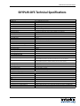
SKYPLAY-DFS Technical Specifications������������������������������������������������������������������������������������������������������������� 20
SKYPLAY-DFS-EU Technical Specifications�������������������������������������������������������������������������������������������������������� 21
FCC Warning��������������������������������������������������������������������������������������������������������������������������������������������������� 22
FCC and IC Radiation Exposure Statement�������������������������������������������������������������������������������������������������������� 22
4
SKYPLAY-DFS Installation Guide
Product Overview
The SKYPLAY-DFS distributes HDMI high-definition audio and video up to 30 meters (100 feet) in both point-topoint, point-to-many, and many-to-point configurations. Each transmitter is compatible with up to 4 receivers and
each receiver can be paired to switch up to 4 transmitters.
The SKYPLAY-DFS-S can transmit 1080p video with stereo or multichannel audio. The SKYPLAY-DFS-R can transmit
IR signals from the remote location to control the source device. The SKYPLAY-DFS transmitter and receiver must
be paired together to pass video.
The SKYPLAY-DFS radios are configured for US and Canada operation. The SKYPLAY-DFS-EU radios are configured
for Europe and Australia operation.
The instructions in this manual will make references to SKYPLAY-DFS, which also applies to SKYPLAY-DFS-EU.
Package Contents
Please verify the following items are in the shipping box prior to installation of the DIGI-88FS.
SKYPLAY-DFS-S Package Contents
1 ea
1 ea
1 ea
1 ea
SKYPLAY-DFS-S Wireless Transmitter
IR Emitter
HDMI Cable
5V DC Power Supply
SKYPLAY-DFS-R Package Contents
1 ea
1 ea
1 ea
1 ea
SKYPLAY-DFS-R Wireless Receiver
IR Remote Control
HDMI Cable
5V DC Power Supply (USB)
5
SKYPLAY-DFS Installation Guide
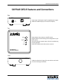
SKYPLAY-DFS-S Features and Connections
Top
Link LED–Indicates network status. LED will be solid during
normal operation.
Video LED–Indicates the video stream is present.
Power LED–Indicates power is applied to transmitter.
Register Button–Pressed during initial configuration to pair
with receiver.
Reset Button–Press for soft reboot of transmitter.
Link
Video
Power
Register
Reset
TX / TRANSMITTER
SKYPLAY-DFS-S
Front
Power Input–5V DC power input for supplied power supply.
Service Port–Only used for firmware updates.
5vDC 1.5A Max
Service
Right
HDMI Input
6
IR Out
HDMI Input–HDMI input port to connect to source device.
IR Out Port–Remote control of source from wireless receiver.
SKYPLAY-DFS Installation Guide
SKYPLAY-DFS-R Features and Connections
Rear
5vDC
1.5A Max
Power
Power Input–5V DC power input for supplied power supply.
HDMI Out–HDMI output port to connect to display.
HDMI Out
Top
Power
Register
Link
Video
Power Button–Press power on and off receiver.
Register Button–Pressed during initial configuration to pair
with receiver.
Link LED–Indicates network status. LED will be solid during
normal operation.
Video LED–Indicates the video stream is present.
RX / RECEIVER
SKYPLAY-DFS-R
Front
IR Receiver–Receives IR signal for source device and sends
it to source through transmitter.
7
SKYPLAY-DFS Installation Guide
IR Remote
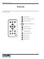
The included IR remote performs all of the pairing and source selection operations of the SKYPLAY-DFS wireless
HD distribution system.
Enter the menu
Return to the previous menu
MENU
EXIT
SOURCE
Select video source
Up, down, left, right for menu
Confirm selection
Remove video source
DELETE
ADD
GUEST
Add video source
INPUT DEVICES
Power off the receiver
Select source 1
Select source 2
Select source 3
8
SKYPLAY-DFS Installation Guide
Installation Instructions
Quick Start
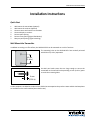
1.
2.
3.
4.
5.
6.
7.
Wall mount the transmitter (optional)
Wall mount the receiver (optional)
Connect source and control to transmitter
Connect display to receiver
Point-to-point pairing
Point-to-many pairing (signal distribution)
Many-to-point pairing (signal switching)
Wall Mount the Transmitter
In addition to resting on a flat surface, the SKYPLAY-DFS-S can be mounted on a wall or furniture.
The mounting holes on the SKYPLAY-DFS-S are vertically oriented
with 620 mm (2.44 in) separation.
62 mm
(2.44 in)
Use #10 pan head screws that are long enough to secure the
transmitter to the wall while also providing a 6 mm (0.24 in) space
to reach the mounting holes.
6 mm
(0.24 in)
A scale template is included in the Quick Start Guide that accompanies the product. Letter and A4 sized templates
are available on the Intelix website (www.intelix.com).
9
SKYPLAY-DFS Installation Guide
Wall Mount the Receiver
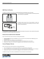
In addition to resting on a flat surface, the SKYPLAY-DFS-R can be mounted on a wall or furniture.
The mounting holes on the SKYPLAY-DFS-R are horizontally oriented
with 475 mm (1.87 in) separation.
475 mm
(1.87 in)
Use #8 pan head screws that are long enough to secure the
transmitter to the wall while also providing a 8 mm (0.31 in) space
to reach the mounting holes.
8 mm
(0.31 in)
A scale template is included in the Quick Start Guide that accompanies the product. Letter and A4 sized templates
are available on the Intelix website (www.intelix.com).
Connect Source and Control to Transmitter
Please review the location of all ports before proceeding with installation.
1. Connect an HDMI cable between the HDMI port on the source device to be extended and the HDMI Input port on
the SKYPLAY-DFS-S.
2. Plug the IR emitter into the IR Out port on the SKYPLAY-DFS-S.
3. Remove the adhesive on the IR emitter. Attach the emitter to the IR window on the source device.
4. Plug the power supply into a wall outlet. Do not apply power to the SKYPLAY-DFS transmitter at this time.
Connect Display to Receiver
Please review the location of all ports before proceeding with installation.
1. Place the SKYPLAY-DFS-R in a location where the IR Receiver is not blocked by any obstructions.
2. Connect an HDMI cable between the HDMI Out port on the SKYPLAY-DFS-R and the HDMI Input port on the display.
3. Plug the power supply into a wall outlet. Do not apply power to the SKYPLAY-DFS receiver at this time.
In addition to resting on a flat surface, the SKYPLAY-DFS-R can be mounted on a wall or furniture.
10
SKYPLAY-DFS Installation Guide
Point-to-Point Pairing
The SKYPLAY-DFS transmitter and receiver must be paired together to pass video.
Without remote
1.
2.
3.
4.
5.
Apply power to the display.
Plug the power supply with USB connector into the Power Input port on the SKYPLAY-DFS-R.
Plug the power supply into the Power Input port on the SKYPLAY-DFS-S.
Apply power to the source device.
Press and hold the Register button on the SKYPLAY-DFS-R until the following message appears on the display:
Please Activate Registration on Transmitter Unit
6. Press and hold the Register button on the SKYPLAY-DFS-S until the following message appears on the display:
Adding transmitter name. Press OK to continue or Exit to cancel
7. Press the Register button on the SKYPLAY-DFS-R to confirm.
8. The following message with a progress bar will appear on the display while the devices are paired:
Adding transmitter name...
9. When pairing is complete, the message and progress bar will be removed from the display. The Link and Video LEDs
on SKYPLAY-DFS-R the will be lit. Video from the source device will pass to the display.
11
SKYPLAY-DFS Installation Guide
With remote
1.
2.
3.
4.
Apply power to the display.
Plug the power supply with USB connector into the Power Input port on the SKYPLAY-DFS-R.
Plug the power supply into the Power Input port on the SKYPLAY-DFS-S.
Apply power to the source device.
5. Press the Exit button to cancel searching for a SKYPLAY-DFS-S.
Searching . . .
6. Press the OK button to enter the Setup menu.
Select Video Source
Setup
7. Press the OK button to initialize the pairing process.
Setup
Add new Video Source
Remove Video Source
Modify Video Source Name
Disconnect Wireless Link
8. Press and hold the Register button on the SKYPLAY-DFS-S.
Please Activate Registration on Transmitter Unit
12
SKYPLAY-DFS Installation Guide
Adding INX000461
9. Once an active SKYPLAY-DFS-S is found, press OK on the remote to
start the pairing process.
Press OK to continue or Exit to cancel
Adding INX000461
10. The display will show the progress of the pairing status with the
SKYPLAY-DFS-S.
11. Once pairing is complete, a brief message will show the
Connected to INX000461
SKYPLAY-DFS-S is paired with the SKYPLAY-DFS-R before starting to
transmit video.
Note:
No WHDI source was found
If the SKYPLAY-DFS-S was too far away or the Register button was not
pressed and held within 60 seconds, a “source not found” message
will appear on the display. Please repeat the pairing process.
13
SKYPLAY-DFS Installation Guide
Point-to-Many Pairing (Signal Distribution)
Below are the steps necessary to pair additional SKYPLAY-DFS receivers to the transmitter for a point-to-many installation.
The maximum number of active receivers that may be connected to a single transmitter is four.
1. Power off all paired SKYPLAY-DFS receivers.
2. Repeat the process for point-to-point pairing.
3. Apply power to all receivers after pairing is complete on all units.
Many-to-Point Pairing (Signal Switching)
Pairing multiple transmitters to a single receiver is performed with the remote control.
1.
2.
3.
4.
5.
6.
14
Power off all paired SKYPLAY-DFS transmitters.
Apply power to the unpaired SKYPLAY-DFS-S.
Select And New Video Source from the Setup menu.
Repeat the process for point-to-point pairing.
Apply power to all transmitters after pairing is complete on all units.
Use the remote control to switch between available transmitters.
SKYPLAY-DFS Installation Guide
Additional SKYPLAY-DFS-R Menu Options
Pressing the Menu button on the remote will go back to the previous menu. Pressing the Exit button will close the menu
and return to playing back the video stream.
Rename a Transmitter
The SKYPLAY-DFS-R provides an option to modify the name of the transmitter. This is merely an alias for the specific
SKYPLAY-DFS-R being used.
Setup
Add new Video Source
Remove Video Source
Modify Video Source Name
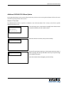
From the Setup menu, arrow down to Modify Video Source Name
and press the OK key on the remote control.
Disconnect Wireless Link
Select the source to rename, then press the OK key.
Choose Source to Rename
INX000461
Rename Video Source
BLUR00461
Use the left and right arrow keys on the remote control to select a
letter to change. Use the up and down arrow keys to cycle through
the available characters.
Once the name has been changed, press the OK key.
15
SKYPLAY-DFS Installation Guide
Remove a Transmitter
The SKYPLAY-DFS-R provides an option to remove a paired SKYPLAY-DFS-S from the available list of transmitters.
Setup
Add new Video Source
Remove Video Source
Modify Video Source Name
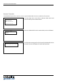
From the Setup menu, arrow down to Remove Video Source and
press the OK key on the remote control.
Disconnect Wireless Link
Select the SKYPLAY-DFS-S to be removed and press the OK button.
Choose Source to Remove
INX000461
INX000772
Removing TX3461
Press OK to continue or Exit to cancel
16
A confirmation message will verify the specify SKYPLAY-DFS-S to be
removed. Press the OK button to remove the transmitter.
SKYPLAY-DFS Installation Guide
Disconnect Wireless Link
The SKYPLAY-DFS-R Disconnect Wireless Link option is available to remove the link between the current receiver and the
transmitter to allow another receiver to accept the video stream.
Select Disconnect Wireless Link from the Setup menu to turn off the
wireless radios in the SKYPLAY-DFS-R.
Setup
Add new Video Source
Remove Video Source
Modify Video Source Name
Press the Source button on the remote to turn the radios back on.
Disconnect Wireless Link
LED States
Link LED
BLINKING MODE
DESCRIPTION
Solid
Connection is established
Link quality is good
Slow (every 3 sec)
Device is in listen mode
Link quality is reasonably good
Normal (every 1 sec)
During link setup mode/during registration
Fast (every 0.1 sec)
System Error (Video LED flashing as well)
Link quality is poor
Video LED
BLINKING MODE
DESCRIPTION
Solid
Video signal is locked
Fast (every 0.1 sec)
System Error (Link LED flashing as well)
Power LED
BLINKING MODE
DESCRIPTION
Solid (blue)
Receive unit is active
Solid (red)
Standby mode
17
SKYPLAY-DFS Installation Guide
Frequently Asked Questions
How many SKYPLAY-DFS-Rs can be connected to one transmitter?
The transmitter will broadcast to four SKYPLAY-DFS-Rs. If a fifth receiver is to replace a currently active SKYPLAY-DFS-R, the
active receiver must disconnect the wireless link or power off before the video stream will pass to the new receiver.
How many SKYPLAY-DFS-Ss can be operational in an installation?
In a theoretical installation that has no outside interference, up to ten transmitters can function. Realistically, up to four
transmitters can operate well.
How close can one SKYPLAY-DFS-S be to another?
In order for the transmitted radio signal to reach the line of sight maximum distance of 100 meters, transmitters should be
positioned at least 2 meters from each other.
How does DFS affect the SKYPLAY-DFS?
When the SKYPLAY-DFS products are first powered on, they will pair on one of the non-DFS channels to establish
communication. After 60 seconds, the SKYPLAY-DFS will start scanning the DFS channels to see which one is available for
use. Once a channel is selected for use, the SKYPLAY-DFS will continue to scan the DFS channels for a backup channel in
case a higher priority signal takes over the first DFS channel.
In the event no non-DFS channels are available, the SKYPLAY-DFS will not play any video and the following message will
appear on the display: Please wait 60 sec, system acquiring DFS frequency. After 60 seconds, the SKYPLAY-DFS
will establish a link on the “best” DFS channel found.
If all non-DFS and DFS channels are occupied, the following message will appear: Connection Failed. The SKYPLAY-DFS
will have to be linked at a later time.
18
SKYPLAY-DFS Installation Guide
Troubleshooting
Pairing Fails
•
•
•
•
Make sure both transmitter and receiver are powered on.
Make sure pairing units are the only SKYPLAY devices currently powered on.
Bring the transmitter and receiver closer together but no closer than 1 meter.
Keep the number of solid walls between the transmitter and receiver to a minimum.
No Signal on the Display
•
•
•
•
•
•
•
•
Make sure the receiver is powered on.
Make sure the monitor is powered on.
Make sure the receiver is properly connected to the display.
Make sure the display is set to display video from the right source (HDMI1, HDMI2 etc.).
Reboot the receiver.
Unplug and then re-plug the HDMI cable between the receiver and the display.
Replace the HDMI cable.
Make sure the video resolution is supported by the display.
No Video over the Wireless Link
•
•
•
•
Make sure the transmitter is properly connected to the source.
Make sure the network LED is powered on.
Make sure the source is powered on.
Unplug and then re-plug the transmitter to the source.
Abnormal Color or Noise on the Display
•
•
•
•
•
Unplug and then re-plug the HDMI cable between the receiver and the display.
Unplug and then re-plug the HDMI cable between the transmitter and the source.
Bring the transmitter and receiver closer together but no closer than 1 meter.
Keep the number of solid walls between the transmitter and receiver to a minimum.
Power cycle the SKYPLAY-DFS.
No Audio
•
•
Check the mute and audio volume settings on the display.
Verify the audio format setting on the source is compatible with the SKYPLAY-DFS.
19
SKYPLAY-DFS Installation Guide
Other Issues
•
The receiver keeps outputting a “Searching…” message, and the NETWORK LED constantly blinks
It should take up to one minute to establish a wireless link. If the link was not established within that time period,
verify the transmitter is powered on and not connected to another receiver.
•
The receiver is outputting “Connected to source name, Please Check Video Source”
Check the HDMI connection between the transmitter and the video source.
•
The receiver displayed a connection failure message and outputs a “Wireless Off” message
If there is more than one registered transmitter, and the receiver failed to connect to it within a minute or two, the
receiver will go into standby mode and shut down the wireless radios. In order to connect to the desired source, press
the Source button on the IR remote and choose the desired source.
•
The Link LED blinks rapidly and there is no video on the display
Power cycle the SKYPLAY-DFS-R. If the issue remains, the device might be faulty. Please contact Liberty AV Solutions
technical support.
•
Link cannot be established or poor video/audio quality
Try to decrease the range between the transmitter and the receiver or remove obstacles out of the way between the
transmitter and receiver.
20
SKYPLAY-DFS Installation Guide
SKYPLAY-DFS Technical Specifications
I/O Connections (SKYPLAY-DFS-S)
HDMI Input
IR Output
5V DC Power
I/O Connections (SKYPLAY-DFS-R)
HDMI Output
5V DC Power
Supported Video, Audio, and Control
Video Resolutions
Color Depth
Video Compliance
Input Video Signal
Input DDC Signal
Embedded Audio
IR Frequency
Signal Characteristics
Wireless Transmission Technology
Signal Bandwidth
Maximum Transmission Distance
Trans mission Rate
Operating Frequency (Non-DFS)
Operating Frequency (DFS)
System Latency
Chassis and Environmental
Material
Dimensions (HxWxD) (SKYPLAY-DFS-S)
Dimensions (SKYPLAY-DFS-R)
Shipping Weight
Operating Temperature
Operating Humidity
Storage Temperature
Storage Humidity
Power, ESD, and Regulatory
Power Supply
Power Consumption
ESD Protection
Regulatory
Other
Warranty
Diagnostic Indicators (SKYPLAY-DFS-S)
Diagnostic Indicators (SKYPLAY-DFS-R)
Included Accessories (SKYPLAY-DFS-S)
Included Accessories (SKYPLAY-DFS-R)
One (1) HDMI Type A Receptacle
One (1) 2.5mm (3/16”) TS Male Connector
One (1) 5.5mm Outside Diameter, 2.1mm Inside Diameter Barrel
One (1) HDMI Type A Receptacle
One (1) Mini USB Type B Connector
480i, 480p, 576i, 576p, 720p, 1080i, 1080p and VESA up to 1920X1080
30-bit
HDMI and HDCP
0.5 – 1.5 volts p-p
5 volts p-p
PCM 2.0, DTS (5.1) and Dolby Digital (5.1)
38KHz
Amimon Pro
40MHz
30.5 m (100 ft)
6.75 Gbps
5.19-5.23 GHz; 5.755-5.795 GHz
5.27-5.59 GHz and 5.67 GHz
<1ms
Black Plastic
With rubber feet: 37 mm x 80.5 mm x 102.3 mm (1.46 in x 3.17 in x 4.03 in)
Without rubber feet: 33 mm x 80.5 mm x 102.3 mm (1.30 in x 3.17 in x 4.03 in)"
With rubber feet: 33 mm x 95 mm x 95 mm (1.30 in x 3.74 in x 3.74 in)
Without rubber feet: 28 mm x 95 mm x 95 mm (1.10 in x 3.74 in x 3.74 in)"
0.91 kg (2 lbs.)
-10° to +40° C (+14° to +104° F)
15% to 85%, Non-condensing
-20° to +80° C (-4° to +176° F)
15% to 85%, Non-condensing
5VDC 2.6A
9 watts
15kV
FCC, CE, RoHS
2 years
Power, Link, and Video
Link and Video
Installation Guide, IR emitter, power supply with international adapters, and HDMI cable
Installation Guide, IR remote, power supply with international adapters, and HDMI cable
21
SKYPLAY-DFS Installation Guide
SKYPLAY-DFS-EU Technical Specifications
I/O Connections (SKYPLAY-DFS-S)
HDMI Input
IR Output
5V DC Power
I/O Connections (SKYPLAY-DFS-R)
HDMI Output
5V DC Power
Supported Video, Audio, and Control
Video Resolutions
Color Depth
Video Compliance
Input Video Signal
Input DDC Signal
Embedded Audio
IR Frequency
Signal Characteristics
Wireless Transmission Technology
Signal Bandwidth
Maximum Transmission Distance
Trans mission Rate
Operating Frequency (Non-DFS)
Operating Frequency (DFS)
System Latency
Chassis and Environmental
Material
Dimensions (HxWxD) (SKYPLAY-DFS-S-EU)
Dimensions (SKYPLAY-DFS-R-EU)
Shipping Weight
Operating Temperature
Operating Humidity
Storage Temperature
Storage Humidity
Power, ESD, and Regulatory
Power Supply
Power Consumption
ESD Protection
Regulatory
Other
Warranty
Diagnostic Indicators (SKYPLAY-DFS-S-EU)
Diagnostic Indicators (SKYPLAY-DFS-R-EU)
Included Accessories (SKYPLAY-DFS-S-EU)
Included Accessories (SKYPLAY-DFS-R-EU)
22
One (1) HDMI Type A Receptacle
One (1) 2.5mm (3/16”) TS Male Connector
One (1) 5.5mm Outside Diameter, 2.1mm Inside Diameter Barrel
One (1) HDMI Type A Receptacle
One (1) Mini USB Type B Connector
480i, 480p, 576i, 576p, 720p, 1080i, 1080p and VESA up to 1920X1080
30-bit
HDMI and HDCP
0.5 – 1.5 volts p-p
5 volts p-p
PCM 2.0, DTS (5.1) and Dolby Digital (5.1)
38KHz
Amimon Pro
40MHz
30.5 m (100 ft)
6.75 Gbps
5.19-5.23 GHz
5.27-5.67 GHz
<1ms
Black Plastic
With rubber feet: 37 mm x 80.5 mm x 102.3 mm (1.46 in x 3.17 in x 4.03 in)
Without rubber feet: 33 mm x 80.5 mm x 102.3 mm (1.30 in x 3.17 in x 4.03 in)"
With rubber feet: 33 mm x 95 mm x 95 mm (1.30 in x 3.74 in x 3.74 in)
Without rubber feet: 28 mm x 95 mm x 95 mm (1.10 in x 3.74 in x 3.74 in)"
0.91 kg (2 lbs.)
-10° to +40° C (+14° to +104° F)
15% to 85%, Non-condensing
-20° to +80° C (-4° to +176° F)
15% to 85%, Non-condensing
5VDC 2.6A
9 watts
15kV
FCC, CE, RoHS
2 years
Power, Link, and Video
Link and Video
Installation Guide, IR emitter, power supply with international adapters, and HDMI cable
Installation Guide, IR remote, power supply with international adapters, and HDMI cable
SKYPLAY-DFS Installation Guide
FCC Warning
This module complies with FCC regulations. Any changes or modifications not expressly approved by the responsible
party could void the user’s authority to operate this equipment.
Notice:
• This module in its final integration requires the end-product to continue to comply with DFS requirements. A
class II permissive change may be required for operation not already described in the FCC Grant filing.
• The OEM of final integrator must ensure that FCC labeling requirements are met for a host using this module, if
(1) the module’s FCC ID is not visible when installed in the host, or (2) if the host is marketed so that end users
do not have straightforward commonly used methods for access to remove the module so that the FCC ID of
the module is visible; then an additional permanent label referring to the enclosed module should be used,
with the following contents: Contains TX FCC ID: VSQAMNKHIN1. RX FCC ID: YG7ZRF32200
• The host OEM user manual must also contain clear instructions on how end users can find and/or access the
module and the FCC ID. The applicable usage is to be used as a wireless device, connected to the back of a
professional camera and transmitting live video, coming from BNC connectors.
• Only the supplied approved antenna should be used.
• This equipment has been tested and found to comply with the limits for a Class B digital device, pursuant to part
15 of the FCC Rules. These limits are designed to provide reasonable protection against harmful interference in
a residential installation. This equipment generates, uses and can radiate radio frequency energy and, if not installed and used in accordance with the instructions, may cause harmful interference to radio communications.
However, there is no guarantee that interference will not occur in a particular installation.
FCC and IC Radiation Exposure Statement
This equipment complies with FCC RF radiation exposure limits set forth for an uncontrolled environment.
This transmitter must not be co-located or operating in conjunction with any other antenna or transmitter.
This equipment complies with Part 15 of the FCC Rules. Operation is subject to the following two conditions:
1. This device may not cause harmful interference, and
2. This device must accept any interference received, including interference that may cause undesired
operation.
The antenna used for transmission must be installed to provide a separation distance of at least 20cm from all
persons and must not be co-located or operating in conjunction with any other antenna or transmitter.
23
Thank you for your purchase.
Please contact us with your questions and comments.
Intelix
8001 Terrace Ave, Ste 201
Middleton, WI 53562
Phone: 608-831-0880
Toll Free: 866-462-8649
Fax: 608-831-1833
www.intelix.com
[email protected]
Intelix is a brand of:
11675 Ridgeline Drive
Colorado Springs, Colorado
80921 USA
Phone: 719-260-0061
Fax: 719-260-0075
Toll-Free: 800-530-8998