1
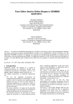
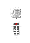
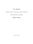
TrueGrid®Output Manual For STARCD®
A Guide and a Reference
by
Robert Rainsberger
Version 2.3.0
XYZ Scientific Applications, Inc.
July 19, 2007
Copyright © 2007 by XYZ Scientific Applications, Inc. All rights reserved.
TrueGrid,® the TrueGrid® Output Manual for STARCD®, and related products of XYZ Scientific Applications, Inc. are
copyrighted and distributed under license agreements. Under copyright laws, they may not be copied in whole or in part
without prior written approval from XYZ Scientific Applications, Inc. The license agreements further restrict use and
redistribution.
XYZ Scientific Applications, Inc. makes no warranty regarding its products or their use, and reserves the right to change its
products without notice. This manual is for informational purposes only, and does not represent a commitment by XYZ
Scientific Applications, Inc. XYZ Scientific Applications, Inc. accepts no responsibility or liability for any errors or
inaccuracies in this document or any of its products.
TrueGrid ®is a registered trademark of XYZ Scientific Applications, Inc.
STARCD® is a registered trademark of CD-adapco, Inc.
Some other product names appearing in this book may also be trademarks or registered trademarks of their trademark holders.
Copyright © 2007 by XYZ Scientific Applications, Inc. All Rights Reserved
ii
July 19, 2007
TrueGrid® Output Manual For STARCD®
Table of Contents
Table of Contents . . . . . . . . . . . . . . . . . . . . . . . . . . . . . . . . . . . . . . . . . . . . . . . . . . . . . . . . . . . . . 3
®
I. STARCD
Output Guide . . . . . . . . . . . . . . . . . . . . . . . . . . . . . . . . . . . . . . . . . . . . . . 5
Font Conventions . . . . . . . . . . . . . . . . . . . . . . . . . . . . . . . . . . . . . . . . . . . . . . . . . . 5
Cell Shapes . . . . . . . . . . . . . . . . . . . . . . . . . . . . . . . . . . . . . . . . . . . . . . . . . . . . . . . 5
STARCD® Commands . . . . . . . . . . . . . . . . . . . . . . . . . . . . . . . . . . . . . . . . . . . . . . 5
STARCD® Input Files . . . . . . . . . . . . . . . . . . . . . . . . . . . . . . . . . . . . . . . . . . . . . . 6
®
II. STARCD
EXAMPLES . . . . . . . . . . . . . . . . . . . . . . . . . . . . . . . . . . . . . . . . . . . . . . . . . . . . 7
®
III. STARCD
OUTPUT REFERENCE . . . . . . . . . . . . . . . . . . . . . . . . . . . . . . . . . . . . . . . . 11
Command Syntax Conventions . . . . . . . . . . . . . . . . . . . . . . . . . . . . . . . . . . . . . . 11
starmats
STARCD® element type selection . . . . . . . . . . . . . . . . . . . . . . . . 12
starbc
STARCD® boundary conditions, regions - part phase . . . . . . . . . 12
starbci
STARCD® boundary conditions, progressions - part phase . . . . 13
starbc
STARCD® boundary conditions of face sets - merge phase . . . . 13
condition
specify type of condition/constraint to be displayed . . . . . . . . . . 14
Copyright © 2007 by XYZ Scientific Applications, Inc. All Rights Reserved
TrueGrid® Output Manual For STARCD® July 19, 2007
3
Copyright © 2007 by XYZ Scientific Applications, Inc. All Rights Reserved
4
July 19, 2007
TrueGrid® Output Manual For STARCD®
®
I. STARCD Output Guide
STARCD® is a three-dimensional simulation code by CD-adapco to model fluid dynamics. The
focus in this manual will be on those features in TrueGrid® that are specific to creating STARCD®
input data. The TrueGrid® User’s Manual covers the creation of a mesh and will not be covered in
this manual. This manual is incomplete in another sense because it cannot be used as a substitute for
a working knowledge of STARCD®.
Font Conventions
Different fonts are used through out this manual to indicate their meaning. A literal is highlighted
in bold. A symbol to be substituted with a literal or a number is italicized. A computer example uses
the Courier font. A button in from the Graphical User Interface is both italic and bold.
Cell Shapes
The typical cell shape is a hexahedron brick. To form a wedge, pyramid, tetrahedron, or other
degenerate brick cell, gather some of the nodes to collapse edges and faces. Then be sure to issue a
merge command in the merge phase, such as the stp command, so that coincident nodes are merged
into one node. See the STARCD Manual for the allowable degenerate bricks. There is no facility to
cut corners off of a brick cell.
STARCD® Commands
The following is a list of TrueGrid® commands that can be used to produce features that are unique
to STARCD® input data.
STARCD® feature
TrueGrid® commands
choose STARCD® format
associate an element type with a material
assign boundary conditions
starcd
starmats
starbc, starbci
Use the standard parts commands (block or cylinder) to generate a brick mesh. The element type
is set by defining a material with the starmats command. Then elements are assigned a material
number using the mate, mt, mti and mtv commands. Use the starbc and starbci commands in the
part phase to specify boundary conditions. Alternatively, you can use the starbc command with face
sets to define boundary conditions in the merge phase.
Copyright © 2007 by XYZ Scientific Applications, Inc. All Rights Reserved
TrueGrid® Output Manual For STARCD® July 19, 2007
5
STARCD® Input Files
The starcd command identifies the STARCD® file format for the output of nodes, bricks, and
boundary conditions for STARCD®, version 3. The starcd command must be issued anytime before
the write command in the merge phase. When the write command is issued, three files will be
written. The default family name for these files is trugrdo. The family name can be specified on the
TrueGrid® execute line or specified with the mof command. Each file is named using a suffix which
is added to the family name. The file with the suffix (or file type) .vrt will contain the nodal or
vertex data. The file with the suffix .cel will have the element or cell data. The file with the suffix
.bnd will have the boundary conditions data. Be sure to issue a nodal merge command, such as stp,
before issuing the write command.
The STARCD® input file with the suffix .inp is not produced by TrueGrid®. This file is a collection
of prostar commands that gets everything else read. You should create this file and the use
IFILE,casename.inp
to begin importing. This file is strictly ascii and free format with as many lines as you need.
Anything starting with '!' is a comment. There are additional fields in all these commands that you
can enter but it would be best to look at the STARCD® manual to decide how much of them you
need. This is the minimum.
TITLE
Put the title here
!Define the cell tables and cell table names
!Solids are ignored if conjugate heat transfer is off.
CTABLE,1,OPTION
CTNAME,1,NAME_FOR_CELL_TYPE_1
CTABLE,2,OPTION
CTNAME,2,NAME_FOR_CELL_TYPE_2
..
CTABLE,N,OPTION
CTNAME,N,NAME_FOR_CELL_TYPE_3 (no spaces)
!Read in cells and vertices
CREAD,casename.cel
VREAD,casename.vrt
!Define boundary region names and read boundaries
RNAME,1,name_of_region_1
RNAME,2,name_of_region_2
BREAD,casename.bnd
Copyright © 2007 by XYZ Scientific Applications, Inc. All Rights Reserved
6
July 19, 2007
TrueGrid® Output Manual For STARCD®
®
II. STARCD EXAMPLES
The following example creates a complete model for STARCD® and produces the three files named
fourpipes.vrt, fourpipes.cel, and fourpipes.bnd. This problem is formed by intersecting four pipes.
Three of the pipes are inlets and the fourth is an outlet.
title Four Intersecting pipes
c Choose the output format
starcd
c Choose the element type for material number 1
starmats 1 fluid ;
c Create the geometry
sd 1 cy 0 0 0 0 0 1 1
sd 2 cy 0 0 0 0 1 0 1
sd 3 plan 0 0 0 0 1 0
sd 4 plan 0 0 0 0 1 1
sd 5 plan 0 0 0 0 1 -1
sd 6 cy 0 0 0 0 0 1 .7
c Use Transfinite Interpolation
intyp 2
c Create a part
block 1 11 19 29;1 11 19 29;1 9;-.3 -.3 .3 .3 -.3 -.3 .3 .3 1 2
c Delete the butterfly corner blocks
dei 1 2 0 3 4; 1 2 0 3 4;;
c Project to the outer cylinder
sfi -1 -4; -1 -4;;sd 1
c Insert a mid partition
insprt 1 4 2 4
c Position the vertices
pb 1 4 1 1 4 1 xyz -6.846159e-01 7.065985e-01 7.097514e-01
pb 2 5 1 2 5 1 xyz -6.846159e-01 7.065985e-01 7.097514e-01
pb 3 5 1 3 5 1 xyz 6.846159e-01 7.065985e-01 7.097514e-01
pb 4 4 1 4 4 1 xyz 6.846159e-01 7.065985e-01 7.097514e-01
pb 4 2 1 4 2 1 xyz 6.846159e-01 -7.065985e-01 7.097514e-01
pb 3 1 1 3 1 1 xyz 6.846159e-01 -7.065985e-01 7.097514e-01
pb 2 1 1 2 1 1 xyz -6.846159e-01 -7.065985e-01 7.097514e-01
pb 1 2 1 1 2 1 xyz -6.846159e-01 -7.065985e-01 7.097514e-01
c Glue the butterfly faces together
bb 3 2 1 4 2 2 1;bb 3 1 1 3 2 2 1;
bb 2 1 1 2 2 2 2;bb 1 2 1 2 2 2 2;
bb 1 4 1 2 4 2 3;bb 2 4 1 2 5 2 3;
bb 3 4 1 3 5 2 4;bb 3 4 1 4 4 2 4;
c Project to various planes for precision
sfi ; -3;;sd 3
sfi -1 0 -4;; -1;sd 2
Copyright © 2007 by XYZ Scientific Applications, Inc. All Rights Reserved
TrueGrid® Output Manual For STARCD® July 19, 2007
7
sfi 2 3; -1 0 -5; -1;sd 2
sfi ; 1 3; -1;sd 4
sfi ; 3 5; -1;sd 5
c Insert partitions for the boundary layer
insprt 1 1 4 5
insprt 1 2 1 5
insprt 1 3 5 5
insprt 1 4 1 5
c Position additional vertices
pb 4 3 2 4 3 2 xyz 2.999967e-01 -2.999968e-01 2.000000e+00
pb 4 5 2 4 5 2 xyz 3.000000e-01 3.000000e-01 2.000000e+00
pb 3 5 2 3 5 2 xyz -3.000000e-01 3.000000e-01 2.000000e+00
pb 3 3 2 3 3 2 xyz -2.999967e-01 -2.999968e-01 2.000000e+00
pb 4 5 1 4 5 1 xyz 3.000000e-01 3.000000e-01 3.000000e-01
pb 3 5 1 3 5 1 xyz -3.000000e-01 3.000000e-01 3.000000e-01
pb 4 3 1 4 3 1 xyz 3.000000e-01 -3.000000e-01 3.000000e-01
pb 3 3 1 3 3 1 xyz -3.000000e-01 -3.000000e-01 3.000000e-01
c Project to the boundary layer cylinder
sfi -2 -5; -2 -6;;sd 6
c Cluster the nodes toward the boundary
res 3 1 1 4 2 2 j 1.25
res 3 6 1 4 7 2 j [1/1.25]
res 5 3 1 6 5 2 i [1/1.25]
res 1 3 1 2 5 2 i 1.25
res 2 4 1 5 4 2 i 1
c Smooth the interior
unifm 2 3 2 5 4 2 & 3 2 2 4 3 2 25 0.0 1.0 ;
unifm 2 4 2 5 5 2 & 3 5 2 4 6 2 25 0 1 ;
unifm 2 3 1 5 4 1 & 3 2 1 4 3 1 25 0 1 ;
unifm 2 4 1 5 5 1 & 3 5 1 4 6 1 25 0 1 ;
c Assign material 1 to this mesh
mate 1
c Replicate the part
lct 3 rx 90;rx 180;rx 270;
lrep 0 1 2 3 ;
endpart
c Enter the merge phase
merge
c Merge identical nodes
stp .001
c Create surfaces to select face sets
sd 7 plan 0 0 -2 0 0 1
sd 8 plan 0 -2 0 0 1 0
sd 9 plan 0 0 2 0 0 1
sd 10 plan 0 2 0 0 1 0
c Create the face sets
fset face1 = surface 7 .01 4
Copyright © 2007 by XYZ Scientific Applications, Inc. All Rights Reserved
8
July 19, 2007
TrueGrid® Output Manual For STARCD®
fset face2 = surface 8 .01 4
fset face3 = surface 9 .01 4
fset face4 = surface 10 .01 4
c Assign boundary conditions
starbc fset face1 1 0 inlet
starbc fset face2 2 0 inlet
starbc fset face3 3 0 inlet
starbc fset face4 4 0 outlet
c Create the input files for STARCD
mof fourpipes
write
Co starbc 4 was used to display the faces forming the outlet
Copyright © 2007 by XYZ Scientific Applications, Inc. All Rights Reserved
TrueGrid® Output Manual For STARCD® July 19, 2007
9
Copyright © 2007 by XYZ Scientific Applications, Inc. All Rights Reserved
10
July 19, 2007
TrueGrid® Output Manual For STARCD®
®
III. STARCD OUTPUT REFERENCE
The syntax for commands are described below were literals are highlighted in bold. Symbols to be
substituted are italicized. Each command is described by an entry like the following:
Command Syntax Conventions
When an arbitrarily long list of arguments are required, a semi-colon terminates the list. When a
semi-colon is found in the description of an option or command, this indicates such a list. It is
common to have a list inside another list. Each list must have a terminating semi-colon. This is
analogous to parenthesis in algebraic expressions where the opening parenthesis must be balanced
with a closing parenthesis. In this case, the keyword that initiates a list of items must be balanced
with a closing semi-colon. Sometimes a short list of arguments and options can be repeated
indefinitely, forming a list. The set of arguments and options that can be repeated are placed in
square brackets. Sometimes the abbreviation #_things is used to mean “number of things”. Each
command is described by an entry like the following:
command
summary description
command arguments
brief description of functionality
with brief descriptions of what the arguments should be.
indentation is used to indicate a list of options to the arguments
Some commands in the part phase require a region specification. The region selects a face of the
mesh, among other things. Others may require a progression specification. The progression selects
multiple faces, among other things. In the merge phase, such commands require an option. In all of
these cases, a portion of the mesh is identified.
Remarks
When present, the Remarks section describes the command in even greater detail. It may describe
the context in which the command is normally used, and other commands used in association with
this command. It may describe side effects. It may describe other, similar commands. In many
cases, it includes a description of where to find the command in the menus.
Examples
When present, this shows the exact use of the command. If you use the dialogues, this command will
be generated by simple selection options with the mouse and entering data where indicated. The
command, as shown here, will appear in the session file for later reuse and possible modification.
Copyright © 2007 by XYZ Scientific Applications, Inc. All Rights Reserved
TrueGrid® Output Manual For STARCD® July 19, 2007
11
You can also enter the command into the text window or insert it into a command file to be run in
batch mode.
starmats
STARCD® element type selection
starmats material_# type ;
where type can be
fluid
solid
baffle
Remarks
The element type is set by defining a material with the starmats command. Then elements are
assigned a material number using the mate, mt, mti and mtv commands.
starbc
STARCD® boundary conditions, regions - part phase
starbc i1 j1 k1 i2 j2 k2 region_id radiation_id type
where type can be
inlet
outlet
symplane
wall
cyclic
stagnation
pressure
baffle
freestream
transient
attach
radiation
degas
riemann
internal
npressure
nrstagnation
Copyright © 2007 by XYZ Scientific Applications, Inc. All Rights Reserved
12
July 19, 2007
TrueGrid® Output Manual For STARCD®
Remarks
The region_id and the radiation_id are required by STARCD®. Only the region_id is used in
TrueGrid® to choose the boundary condition to be displayed (see the co command). The
radiation_id plays no role in TrueGrid® and is simply passed onto the *.bnd boundary output file.
starbci
STARCD® boundary conditions, progressions - part phase
starbci i_list; j_list; k_list; region_id radiation_id type
where type can be
inlet
outlet
symplane
wall
cyclic
stagnation
pressure
baffle
freestream
transient
attach
radiation
degas
riemann
internal
npressure
nrstagnation
Remarks
The region_id and the radiation_id are required by STARCD®. Only the region_id is used in
TrueGrid® to choose the boundary condition to be displayed (see the co command). The
radiation_id plays no role in TrueGrid® and is simply passed onto the *.bnd boundary output file.
starbc
STARCD® boundary conditions of face sets - merge phase
starbc fset_set_name region_id radiation_id type
where the region type can be
inlet
Copyright © 2007 by XYZ Scientific Applications, Inc. All Rights Reserved
TrueGrid® Output Manual For STARCD® July 19, 2007
13
outlet
symplane
wall
cyclic
stagnation
pressure
baffle
freestream
transient
attach
radiation
degas
riemann
internal
npressure
nrstagnation
Remarks
Each region ID is assumed to consist of a contiguous area of a boundary. If you do not specifically
call out a boundary on an exterior face, it assumes that face belongs to the region identified with 0.
You can set region 0 to any region type but most commonly its set to be a wall.
A face set is created and modified using the fset and fseti commands in the part phase and the fset
command in the merge phase. A fset can also be created or modified using the Sets button in the
Pick panel of the Environment Window while in the merge phase. A face set is named at the time
it is created and any character string can be used to name it.
The region_id and the radiation_id are required by STARCD®. Only the region_id is used in
TrueGrid® to choose the boundary condition to be displayed (see the co command). The
radiation_id plays no role in TrueGrid® and is simply passed onto the *.bnd boundary output file.
condition
specify type of condition/constraint to be displayed
condition starbc region_id
or
co starbc region_id
Copyright © 2007 by XYZ Scientific Applications, Inc. All Rights Reserved
14
July 19, 2007
TrueGrid® Output Manual For STARCD®