1
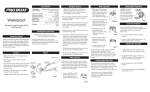
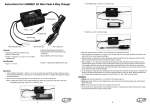
Servo Ratings with BEC Enabled:
Cells
High Torque
Servos
6 - 8 Ni-Cd/Ni-MH
9 - 10 Ni-Cd/Ni-MH
2 Li-Po
3 Li-Po
25-Amp Pro Brushless ESC
Instructions
Thank you for purchasing the E-flite® 25-Amp Pro Brushless
ESC. This controller has been designed for use in radio
control aircraft and to support continuous currents of up to
25 amps when using 2-3 cell Li-Po battery packs and up to
four sub-micro servos. The ESC features a lightweight
plastic case, with exposed, finned heat sinks for both the
motor drive mosfets, and unlike many controllers, the BEC
regulators give you a more reliable and powerful power
supply for your servos.
• Up to 25 amps continuous current with proper air flow
• Finned heat sinks for both the motor drive mosfets and dual BEC
regulators to support up to 4 sub-micro servos
• Programmable motor braking
• Safe power-arm mode prevents accidental starts
• Programmable low voltage cut-off with settings for 2-cell Li-Po (6V),
3-cell Li-Po (9V) or 70% of battery starting voltage
• Programmable throttle input range (1.1ms-1.9ms or Auto Select)
• Soft start
• Auto motor shut down if signal is lost or there is interference
• Programmable timing—2 user selectable ranges for use with a large
variety of brushless motors
• Pre-wired connectors—E-flite EC3 on battery input and 3.5mm
female gold bullets on motor output leads
Continuous Current:
Max Burst Current:
Length:
Width:
Height:
Weight:
Cells:
Battery Input Leads:
Motor Output Leads:
4
3
4
3
Sub-Micro
Servos
4**
4**
4**
4**
** Sub-Micro Servos tested 4 at a time include E-Flite S-60, and S-75, JR 241, and ParkZone 3W servo.
Some other brands of servos have significantly higher current draw. Digital sub-micro servos, micro, and
mini-servos have higher current draw, use the 'standard servos' column. Always be sure to position the ESC
for maximum airflow since cooling can significantly aid in the performance of the BEC.
25A
30A (15 sec)
48mm (1.9 in)
28mm (1.1 in)
11mm (.4 in)
32 g (1.2 oz)
2-3S Li-Po or 6-10 Ni-MH/Ni-Cd
16 AWG with E-flite EC3 Connector
16 AWG with 3.5mm Female Gold Bullet Connectors
the ESC, battery, and motor after each flight. You may want to consider
letting the electronic components cool to near ambient temperature
between flights.
We also recommend throttle management when running near maximum
levels of current draw. It is not recommended you fly an entire flight at full
throttle. If this is done, it is possible to cause permanent damage to your
motor, battery, and ESC.
Using the 25-Amp Pro Brushless Controller
Before first use, please refer to the above chart for BEC usage and input
voltage/cell count guidelines. You must follow these guidelines for safe
operation. If you are using four servos with higher current draw, or more
than four servos for a quad flap option (for example), you will need to
disable the BEC. If you wish to disable the BEC, you must remove the red
receiver wire lead and connector from the receiver lead housing, and then
insulate it properly to prevent shorting.
This controller is very simple to use, and for safety, will not arm the motor
until the throttle stick has been held in the Idle/Off position for more than
1 second. The controller will indicate the soft cut-off voltage setting every
time you plug the battery in by first emitting a low, long tone, to show
startup. You will then hear 2 (for 2-cell Li-Po) or 3 (for 3-cell Li-Po)
medium length, mid tones to indicate the cell count (or 7 beeps
if 70% Smart Cut is selected), helping you to confirm the setting before
every flight.
When operating with the BEC disabled, E-flite recommends the use of a
separate, high power, external, BEC (like the Ultimate BEC), or receiver
pack and switch using the following items to ensure trouble-free operation:
Connecting the ESC to the Motor
1. Expert 720mAh Ni-MH 4.8V receiver battery (EXRB100), or similar
2. Expert Standard Switch (EXRA050), or similar
PLEASE READ THESE INSTRUCTIONS
IN THEIR ENTIRETY BEFORE USE
Features:
Specifications:
3
2
3
2
Standard
Servos
The three wires from your motor connect to the three female gold bullet
connectors on the ESC. The order of connection to the motor is not
important; you can plug any motor wire into any connector. If, when you
test the system, the motor runs backwards, you can simply unplug and
switch any two of the motor wire plugs connected to the ESC.
Mounting the ESC
Choose a location that has good airflow and offers good protection.
Before you connect your ESC and begin flying, take a moment to look it
over. The input power side has a black (negative) and red (positive) wire
along with an E-flite EC3 Male Device Connector. The motor side has three,
3.5mm female gold bullet connectors.
The black and red wires with the EC3 DEVice (DEV) Connector will
connect to your power battery. The red wire connects to the red wire on
your battery pack, the black wire connects to the black wire on your
battery pack. If the wires are reversed, the ESC may be damaged. YOU
MUST ENSURE THAT YOU CONNECT THE BATTERY POLARITY PROPERLY TO
PREVENT DAMAGE TO THE ESC. Reversing polarity will void your warranty,
so always double-check this connection. You may need to solder an E-flite
EC3 Female Battery (BATT) Connector (EFLAEC302) to the battery so it
matches this speed control. The throttle lead connects to the throttle
channel on your radio receiver.
WARNING: For your safety, when checking the startup function of the ESC
or making programming changes, please remove the propeller to prevent any
potential injury. You should always treat the motor and propeller as live and
dangerous, remembering it could start at any time, and keep any body parts,
clothing and tools clear of the propeller arc. NEVER LEAVE THE BATTERY
CONNECTED WHEN NOT FLYING THE AIRCRAFT AND ALWAYS REMOVE THE
BATTERY FROM THE MODEL BEFORE CHARGING AND WHEN FINISHED FLYING.
When flying in hot weather, we recommend checking on the condition of
The plastic case area next to the small BEC heat sink is designed to accept
Velcro® or 2-sided tape. Do not cover the heat sinks as this will greatly
reduce their effectiveness.
Mount the ESC with a combination of Velcro®, 2-sided foam tape, and/or
tie wraps.
Starting Your Power System
1. Turn on your transmitter and ensure the position of the throttle
stick is set to Idle/Off.
2. Plug in the flight pack to the controller and listen for the tones
to indicate voltage cut-off.
3. After the controller has indicated the cell count, you will here a
series of 3 medium length rising tones to indicate the controller
is armed, and ready to fly.
4. When you move the throttle stick upward, the motor will run. If
you continue to move the throttle stick upward to Full throttle
(high position), the motor will run faster. If you lower the throttle
stick below the start-up position, the motor will stop running.
5. Check servo motion as part of your preflight check. It is very
important you make sure linkages are free-moving with no binding.
(continued on back)
(continued)
Entering the Programming Mode
1. With the battery disconnected from the controller, and the transmitter
turned on, first move the throttle stick to full throttle (>1.7ms)
position. Leave it in this position and then connect the battery to
the controller.
2. Wait for 5 seconds, and the ESC will give two sets of fast ringing tones
to indicate you have successfully entered the programming mode.
3. Once you hear these tones, move the stick to center (between 1.4
and 1.6ms), and the controller will beep 1 time, this indicates
menu item 1.
4. The controller will now wait 5 seconds for you to make your selection;
your programming options are either full throttle (>1.7ms), or idle
(<1.3ms).
5. When you have made a valid selection, the control will beep once
with a lower tone, and you can move the stick back to center for
the next menu item (2 beeps, 3 beeps and so on). If you do not
make a selection within 5 seconds, the controller will move to
the next menu item.
6. Please note that if you do not need to program every menu item,
you can simply exit the programming mode after you have made
the required selections. You can do this by moving the throttle
stick straight to idle after making your selection, or leaving it
in the idle position if you made a no selection (for approximately
8 seconds) until you hear one set of 3 medium length rising
tones that indicate the controller has armed the motor, or by
simply unplugging the battery.
Remember, when in the programming mode:
Full Throttle = Stick Up
Idle = Stick Down
You will know your battery pack has reached soft auto cut-off when you
hear the motor “pulse” repeatedly. We recommend you land your model as
soon as you hear the motor pulse (indicating the pack voltage has dropped
to the cut-off voltage level) to prevent over-discharge of the Li-Po battery
pack, and to prevent sudden power loss.
Programming Menu 2 – Braking
This option gives you the choice to have the ESC stop the propeller during
flight (brake on) or allow it to windmill (brake off). Use the brake on option
for gliders.
1. Brake Off – Full Throttle (>1.7ms)
2. Brake On – Idle (<1.3ms)
Programming Menu 3 – Timing
Please refer to your motor instructions and specifications for an indication
of the number of poles.
1. 4-pole and greater motors timing mode – Full Throttle
2. 2-pole motors timing mode – Idle
Programming Menu 4 – Throttle Input Range
This option allows for proper operation of the ESC with many different
radios on the market. Most radios, and all the computer radios we have
tested, will work well with the auto set option, but some radios have a
wider output range, and may give a more linear response with the 1.1 to
1.9ms range. If you feel there is too much “dead” area in the stick
movement near Full Throttle, try adjusting the end points in your radio, or
change to the wider input range. Be aware that if these settings are not
correct, it may be impossible to arm the controller. If this happens, return
the input range setting to the default auto learning setting.
The default settings (from the package) for your E-flite 25-Amp Pro ESC
are as follows:
• 3S (9V) auto cut-off for Li-Po
• Brake Off
• 4 pole and greater timing (outrunner or 6-pole motors)
• Throttle input range set to Auto Select mode (1.2ms-1.8ms)
The auto setting option learns the minimum position of your throttle
(between 1.1 and 1.3ms) and stores this value at each startup, and then
adds a value of 0.6ms for the full throttle setting.
Programming Menu 1 – Voltage Cut-off
Error Codes
Use this option to set the voltage at which the controller will shut down
the motor to prevent damage to your battery, when it reaches the cut-off
voltage. You will know your battery pack has reached auto cut-off when
you hear the motor “pulse” repeatedly.
1. 3S Li-Po voltage cut-off – Full Throttle
2. 2S Li-Po or Ni-Cd/Ni-MH voltage cut-off – Idle
3. 70% Smart Cut soft cut-off (See below for Smart Cut information)
NOTE: To access the 70% Smart Cut option, leave the stick at full throttle for 7 seconds while in menu item
1, until 7 beeps are heard, then continue through the program normally. This option will activate the soft
cut-off at 70% of startup voltage. For example, if your pack measures 10.0 volts at startup, then the soft
cut will occur at 7.0 volts. The Smart Cut option will check the startup voltage every time you plug the
battery into the controller, so beware of using partially charged packs, as the system cannot protect your
Li-Po batteries if you are using Smart Cut and connect a partially charged pack.
1. Throttle Range 1.1ms to 1.9ms – Full Throttle
2. Auto Select – Idle
The controller will beep continuously if the input voltage is below the cut
voltage (beep...beep...beep) when the battery is connected. Check the
voltage of the battery pack to see if it is correct, or the programmed cut-off
setting if the input voltage is set incorrectly for the voltage of the pack
being used.
If you have trouble arming the controller (and the throttle trim has been
set to minimum), enter the programming mode and try the auto setting
in Programming Menu 4 to see if it helps correct your problem. If it is
a computer radio, you may alternatively increase your high and low throttle
ATV (endpoint) percentages.
Some systems including many Futaba systems may require the throttle
channel to be “reversed” for proper operation.
Limited Warranty Period
Horizon Hobby, Inc. guarantees this product to be free from defects in both
material and workmanship for a period of 1 year from the date of purchase.
Limited Warranty & Limits of Liability
Pursuant to this Limited Warranty, Horizon Hobby, Inc. will, at its option,
(i) repair or (ii) replace, any product determined by Horizon Hobby, Inc. to
be defective. In the event of a defect, these are your exclusive remedies.
This warranty does not cover cosmetic damage or damage due to acts of
God, accident, misuse, abuse, negligence, commercial use, or modification
of, or to any part of the Product. This warranty does not cover damage due
to improper installation, operation, maintenance, or attempted repair by
anyone other than an authorized Horizon Hobby, Inc. service center. This
warranty is limited to the original purchaser and is not transferable. In no
case shall Horizon Hobby’s liability exceed the original cost of the
purchased product and will not cover consequential, incidental or collateral
damage. Horizon Hobby, Inc. reserves the right to inspect any and all
equipment involved in a warranty claim. Repair or replacement decisions
are at the sole discretion of Horizon Hobby, Inc. Further, Horizon Hobby
reserves the right to change or modify this warranty without notice.
REPAIR OR REPLACEMENT AS PROVIDED UNDER THIS WARRANTY IS
THE EXCLUSIVE REMEDY OF THE CONSUMER. HORIZON HOBBY, INC.
SHALL NOT BE LIABLE FOR ANY INCIDENTAL OR CONSEQUENTIAL
DAMAGES.
As Horizon Hobby, Inc. has no control over use, setup, final assembly,
modification or misuse, no liability shall be assumed nor accepted for any
resulting damage or injury. By the act of use, setup or assembly, the user
accepts all resulting liability.
If you as the purchaser or user are not prepared to accept the liability
associated with the use of this product, you are advised to return this
product immediately in new and unused condition to the place of purchase.
Safety Precautions
This is a sophisticated hobby product and not a toy. It must be operated
with caution and common sense and requires some basic mechanical
ability. Failure to operate this product in a safe and responsible manner
could result in injury or damage to the product or other property. This
product is not intended for use by children without direct adult supervision.
For complete and specific information concerning the Limited Warranty,
Limits of Liability, and Safety Precautions – please refer to our web-page
for this item or contact your E-flite distributor. You can also direct emails
to [email protected], or in the U.S., call 877.504.0233
toll free to speak to a service technician.
© 2006 Horizon Hobby, Inc.
www.horizonhobby.com
www.E-fliteRC.com
E-flite® is an exclusive brand of Horizon Hobby, Inc.
Made in China
9247