1
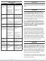
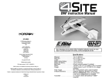
PNP Instruction Manual EFL9050 © 2009 Horizon Hobby, Inc. 4105 Fieldstone Road Champaign, IL 61822 USA Horizon Hobby UK Units 1-4 Ployters Rd Staple Tye Harlow, Essex CM18 7NS United Kingdom Horizon Hobby Deutschland GmbH Hamburger Strasse 10 25335 Elmshorn Germany US patent D578,146 Multiple patents pending PRC patent number ZL 2007 2 0069025.2. E-flite® products are distributed exclusively by Horizon Hobby, Inc. DSM and DSM2 are trademarks or registered trademarks of Horizon Hobby, Inc. The Spektrum trademark is used with permission of Bachmann Industries, Inc. Futaba is a registered trademark of Futaba Denshi Kogyo Kabushiki Kaisha Corporation of Japan. E-fliteRC.com 15395 Printed 8/09 Note: Attempting to fly the airplane without completely reading the manual may cause injury to yourself and people in the vicinity, as well as damaging the aircraft. Specifications Wingspan. . . . . . . . . . . . . . . . . . . 15.2 in (387mm) Wing Area. . . . . . . . . . . . . . . . . . 87.5 in (25.5 sq dm) Length. . . . . . . . . . . . . . . . . . . . . 17.5 in (445mm) Weight without Battery. . . . . . . . . 1.10 oz (31 g) Weight with Battery . . . . . . . . . . . 1.25 oz (35.5 g) Main Motor . . . . . . . . . . . . . . . . . 8.5mm coreless brushed (1 installed) On-Board Electronics . . . . . . . . . . Spektrum AR6400L Ultra-Micro Long Throw Receiver (SPMAR6400L) and 1.5 g Long Throw Linear Servo (SPMAS2000L) (2 installed) Table of Contents Introduction Specifications . . . . . . . . . . . . . . . . . . . . . . . . . . . . . . . . . . . . . . . . . . . . . . . . . . . 1 Introduction. . . . . . . . . . . . . . . . . . . . . . . . . . . . . . . . . . . . . . . . . . . . . . . . . . . . . 3 Additional Safety Precautions and Warnings . . . . . . . . . . . . . . . . . . . . . . . . . . . . . . 4 Note on Lithium Polymer Batteries. . . . . . . . . . . . . . . . . . . . . . . . . . . . . . . . . . . . . 5 Ultra-Micro 4-Site PNP Contents. . . . . . . . . . . . . . . . . . . . . . . . . . . . . . . . . . . . . . . 5 Additional Equipment . . . . . . . . . . . . . . . . . . . . . . . . . . . . . . . . . . . . . . . . . . . . . . 5 Preparing for the First Flight Checklist. . . . . . . . . . . . . . . . . . . . . . . . . . . . . . . . . . 6 Flying Checklist . . . . . . . . . . . . . . . . . . . . . . . . . . . . . . . . . . . . . . . . . . . . . . . . . . 6 Transmitter Preparation . . . . . . . . . . . . . . . . . . . . . . . . . . . . . . . . . . . . . . . . . . . . 7 Transmitter Control Identification. . . . . . . . . . . . . . . . . . . . . . . . . . . . . . . . . . . . . . 7 Installing the Flight Battery . . . . . . . . . . . . . . . . . . . . . . . . . . . . . . . . . . . . . . . . . . 8 Transmitter and Receiver Binding. . . . . . . . . . . . . . . . . . . . . . . . . . . . . . . . . . . . . . 9 Transmitter Specific Binding Instructions . . . . . . . . . . . . . . . . . . . . . . . . . . . . . . . 10 Additional Binding Information. . . . . . . . . . . . . . . . . . . . . . . . . . . . . . . . . . . . . . . 11 Control Test. . . . . . . . . . . . . . . . . . . . . . . . . . . . . . . . . . . . . . . . . . . . . . . . . . . . 12 Control Centering. . . . . . . . . . . . . . . . . . . . . . . . . . . . . . . . . . . . . . . . . . . . . . . . 15 Dual Rates and Expo. . . . . . . . . . . . . . . . . . . . . . . . . . . . . . . . . . . . . . . . . . . . . .16 Setting CG. . . . . . . . . . . . . . . . . . . . . . . . . . . . . . . . . . . . . . . . . . . . . . . . . . . . . 16 Receiver Control Unit Description, Arming and Motor Control Test . . . . . . . . . . . . . 17 Choosing a Flying Area. . . . . . . . . . . . . . . . . . . . . . . . . . . . . . . . . . . . . . . . . . . . 19 Flying the Ultra-Micro 4-Site. . . . . . . . . . . . . . . . . . . . . . . . . . . . . . . . . . . . . . . . . 20 Optional Speed Brakes. . . . . . . . . . . . . . . . . . . . . . . . . . . . . . . . . . . . . . . . . . . . 21 Prop Replacement . . . . . . . . . . . . . . . . . . . . . . . . . . . . . . . . . . . . . . . . . . . . . . . 22 Replacement Parts. . . . . . . . . . . . . . . . . . . . . . . . . . . . . . . . . . . . . . . . . . . . . . . 23 Option Parts . . . . . . . . . . . . . . . . . . . . . . . . . . . . . . . . . . . . . . . . . . . . . . . . . . . 23 Repair . . . . . . . . . . . . . . . . . . . . . . . . . . . . . . . . . . . . . . . . . . . . . . . . . . . . . . . 23 Troubleshooting Guide . . . . . . . . . . . . . . . . . . . . . . . . . . . . . . . . . . . . . . . . . . . . 24 Warranty Information . . . . . . . . . . . . . . . . . . . . . . . . . . . . . . . . . . . . . . . . . . . . . 25 Product Registration. . . . . . . . . . . . . . . . . . . . . . . . . . . . . . . . . . . . . . . . . . . . . . 29 FCC Information. . . . . . . . . . . . . . . . . . . . . . . . . . . . . . . . . . . . . . . . . . . . . . . . . 29 CE Compliance Information for the European Union. . . . . . . . . . . . . . . . . . . . . . . . 30 Congratulations on the purchase of your Ultra-Micro™ 4-Site™. Its amazing performance is the result of many E-flite advances, not the least of which is a stamped-foam manufacturing technique that results in wing, fuselage and tail parts that are actually lighter, stiffer and more durable than standard sheet foam. The airfoil shape of the wing also provides superior performance to sheet foam. These parts are further reinforced with carbon rod and foam bracing that minimizes in-flight flexing and twisting. 2 This robust construction, combined with the precision of Spektrum™ 2.4GHz DSM2™ technology and long-throw Ultra-Micro servos, gives the 4-Site a level of control and responsiveness you will instantly fall in love with. But before you get started, take some time to read this manual. The Ultra-Micro 4-Site is designed for experienced 3D foamy pilots and as such requires a radio capable of supporting dual rates and expo. In addition to basic operation and maintenance instructions, you’ll find valuable radio setup tips that will help make your first flight the best it can be. 3 Additional Safety Precautions and Warnings As the user of this product, you are solely responsible for operating in a manner that does not endanger yourself and others or result in damage to the product or the property of others. This model is controlled by a radio signal that is subject to interference from many sources outside your control. This interference can cause momentary loss of control so it is advisable to always keep a safe distance in all directions around your model, as this margin will help avoid collisions or injury. Note on Lithium Polymer Batteries Lithium Polymer batteries are significantly more volatile than alkaline or Ni-Cd/Ni-MH batteries used in RC applications. All manufacturer’s instructions and warnings must be followed closely. Mishandling of Li-Po batteries can result in fire. Always follow the manufacturer’s instructions when disposing of Lithium Polymer batteries. Ultra-Micro 4-Site PNP Contents Age Recommendation: 14 years or over. This is not a toy. This product is not intended for use by children without direct adult supervision. • Never operate your model with low transmitter batteries. • Always operate your model in an open area away from cars, traffic, or people. • Avoid operating your model in the street where injury or damage can occur. • Never operate the model in the street or in populated areas for any reason. • Carefully follow the directions and warnings for this and any optional support equipment (chargers, rechargeable battery packs, etc.) that you use. • Keep all chemicals, small parts and anything electrical out of the reach of children. • Moisture causes damage to electronics. Avoid water exposure to all equipment not specifically designed and protected for this purpose. • Never lick or place any portion of your model in your mouth as it could cause serious injury or even death. 4 Item Description EFL9050. . . . . . . . . . . . Ultra-Micro 4-Site PNP (airframe with electronics only) Additional Equipment EFLB1501S. . . . . . . . . . 150mAh 1-Cell 3.7V 12C Li-Po EFLC1004. . . . . . . . . . . Celectra 4-Port 1-Cell 3.7V 0.3A DC Li-Po Charger EFLC1005. . . . . . . . . . . 6V, 1.5-Amp AC/DC Power Supply DSM2 Transmitter Note: All DSM2 equipped transmitters and modules will bind to the receiver of the 4-Site but we highly recommend using one of the transmitters listed in this manual (page 9) due to the dual rate and expo functions of these transmitters. 5 Preparing for the First Flight Checklist RC airplanes are not toys. Please note this checklist is not intended to be a replacement for the content included in this manual. Although it can be used as a quick start guide, we strongly suggest you follow this checklist along with the rest of the instruction manual to help you gain important information to operate this RC aircraft successfully. This will help ensure you get the most fun out of your RC experience. q Remove and inspect contents. q Read this instruction manual thoroughly. q Install the flight battery in the airplane (once it has been fully charged). q Bind aircraft to your transmitter (shown on page 9–11 of this manual). q Test the controls (shown on page 12–14 of this manual). Transmitter Preparation Please make sure you have fresh/charged batteries in your transmitter. If applicable, set your transmitter model to the correct Airplane. JR® and Spektrum transmitters’ servo settings should be set to default (normal) servo direction. Futaba transmitters (equipped with Spektrum modules) may require you to reverse the throttle channel. We highly recommend using a radio that is capable of dual rates and expo. Although the 4-Site can be flown on any DSM2 radio, it is recommended that you use a radio with these features due to the quick response and aerobatic nature of the aircraft. Transmitter Control Identification Note: Before each flight you should ALWAYS turn the transmitter on before connecting the flight battery to the receiver unit. After each flight, be sure that you always disconnect the flight battery from the receiver unit before powering the transmitter off. q Familiarize yourself with the controls. q Find a suitable area for flying. Flying Checklist Please note this checklist is not intended to be a replacement for the content included in this instruction manual. Although it can be used as a quick start guide, we strongly suggest reading through this manual and other documentation included with the product completely before proceeding. • Always turn the transmitter on first and set at least 2 feet away from the aircraft • Plug the flight battery into the receiver and install the flight battery • Connect the flight battery into the power lead of the AR6400L receiver • Allow the receiver to initialize and arm properly • Fly the model • Land the model • Disconnect the flight battery from the receiver • Always turn the transmitter off last 6 7 Installing the Flight Battery 1.Install the battery into the fuselage by first plugging the battery into the receiver. Transmitter and Receiver Binding Binding is the process of programming the receiver of the control unit to recognize the GUID (Globally Unique Identifier) code of a single specific transmitter. It will be necessary for you to ‘bind’ your chosen Spektrum DSM2 technology equipped transmitter to the receiver for proper operation. The following is a list of the Spektrum DSM2 equipped transmitters that we suggest using to fly the 4-site and that will bind to the 4-Site receiver: Spektrum DX6i JR X9303 2.4 Spektrum DX7/DX7se JR 12X 2.4 Note: The Spektrum DX6 (SPM2460) is equipped with DSM (not DSM2) technology and is not compatible with the receiver of the 4-Site PNP. 2.Mount the battery in the airplane by placing it onto the bottom of the horizontal fuselage on the right-hand side where the hook and loop strip is located. The plug will face toward the rear of the airplane. Note: All DSM2 equipped transmitters and modules will bind to the receiver of the 4-Site but we highly recommend using one of the transmitters listed above due to the dual rate and expo functions of these transmitters. The following steps outline the binding process: • Confirm the process of entering the bind mode for your chosen transmitter by reviewing the instruction manual included with the transmitter. • Make sure the flight battery is disconnected from the receiver unit and the transmitter is turned off. • Plug the flight battery into the receiver unit. After 5 seconds the LED on the receiver unit will begin flashing. On the 4-Site, look on the left-hand side of the airplane to see the red LED flashing. Note: T he battery can be moved fore and aft to allow for the Center of Gravity adjustment. Start with the battery in the middle of the hook and loop strip. Adjust the battery forward or rearward to fine-tune the center of gravity. • After verifying the LED is flashing on the receiver, follow the steps that allow your chosen transmitter to enter bind mode. • If you entered bind mode correctly, you will see a solid LED approximately 5–10 seconds later on the receiver. You should now be bound to the transmitter, and have full control and function. If you encounter any problems, repeat the binding process again, see the troubleshooting guide or call the Horizon Support Team at 1-877-504-0233. 8 9 Transmitter Specific Binding Instructions DX6i: A. Select a new model memory or the chosen model memory that you want for the 4-Site. B. To bind your 4-Site to the DX6i, plug the battery into the receiver of the airplane. The LED on the receiver will begin flashing. C. Move the sticks and switches on the transmitter to the desired failsafe positions (low throttle and neutral control positions). D. Pull and hold the Trainer Switch on the transmitter while turning the transmitter on. Release the trainer switch once the word BIND flashes on the LCD screen on the front of the transmitter. E. The LED on the receiver will go solid red and the system will connect after several seconds. DX7 (includes DX7se): X9303: A. Select a new model memory or the chosen model memory that you want for the 4-Site. B. To bind your 4-Site to the X9303, plug the battery into the receiver of the airplane. The LED on the receiver will begin flashing. C. Move the sticks and switches on the transmitter to the desired failsafe positions (low throttle and neutral control positions). D. Press the bind button on the back of the transmitter while turning the transmitter on. The bind button on the back of the transmitter will flash. Release the button after 2–3 seconds. E. The LED on the receiver will go solid red and the system will connect after several seconds. 12X: A. Start with a blank model memory, or the one you have selected for the 4-Site. A. Select a new model memory or the chosen model memory that you want for the 4-Site. B. To bind your 4-Site to the DX7, plug the battery into the receiver of the airplane. The LED on the receiver will begin flashing. C. Move the sticks and switches on the transmitter to the desired failsafe positions (low throttle and neutral control positions). D. Press the bind button on the back of the transmitter while turning the transmitter on. The bind button on the back of the transmitter will flash. Release the button after 2–3 seconds. E. The LED on the receiver will go solid red and the system will connect after several seconds. B. To bind your 4-Site to the 12X, plug the battery into the receiver of the airplane. The LED on the receiver will begin flashing. C. Move the sticks and switches on the transmitter to the desired failsafe positions (low throttle and neutral control positions). D. Press the black bind button on the back of the transmitter while turning the transmitter on. Release the button after 2–3 seconds. E. The LED on the receiver will go solid amber and the system will connect after several seconds. Note: Before each flight you should ALWAYS turn the transmitter on before connecting the flight battery to the receiver unit. After each flight, be sure that you always disconnect the flight battery from the receiver unit before powering the transmitter off. Additional Binding Information Prior to each flight, you should ensure that you power on your transmitter and wait about five seconds before you plug the flight battery into the receiver. Doing this allows time for the transmitter to scan and secure two open frequencies. If the flight battery is plugged in too quickly and the link is missed, it may cause the receiver to inadvertently enter bind mode. If this occurs simply leave the transmitter on and then disconnect and reconnect the flight battery. 10 11 Control Test You must test the controls prior to the first flight to ensure none of the servos, linkages or parts were damaged during shipping and handling and that the controls function in the correct directions. Move the aileron stick left and right to check aileron roll control. When the stick is pushed to the left, the left aileron should move up and the right aileron should move down. Turn the transmitter on first and lower the throttle stick completely. Then, plug the battery into the battery lead of the receiver unit. Note: T he connectors on the battery and battery lead are keyed to prevent reverse polarity connection. However, if you force them together in the wrong orientation and with the wrong polarity it is still possible to damage the battery and/or receiver unit. To help further prevent a reverse polarity connection, one side of the end cap on the battery and the connector on the battery lead of the receiver unit will have a red dot. The connectors are oriented for a proper polarity connection when the red dots are on the same side. Move the elevator stick on the transmitter forward and aft to check elevator pitch control. When the stick is pushed forward, the elevator should move down. With the aileron stick pushed right, the right aileron should move up and the left aileron should move down. When the elevator stick is moved aft the elevator should move up. 12 13 Move the rudder stick left and right to check yaw control. When the stick is pushed to the right the rudder should also move to the right. Control Centering In the event of an accident or before first flight, you should check to make sure that the flight control surfaces are centered. It is much better to do this mechanically due to the mechanical limits of linear servos. 1. Make sure that all of your sub-trims are at 0 and your transmitter trims are centered. 2. Check to see if any of the flight control surfaces are not centered. With the rudder stick pushed to the left, the rudder should move to the left. 3. If the surface is not centered, use a pair of pliers and carefully lengthen or shorten the pushrod of that surface by bending the U shape in the pushrod. If at any time during the test the controls respond in the opposite direction, it may be necessary to reverse/change the direction of operation of the flight controls. Follow the Reversing Flight Controls section to change the direction of the various flight controls. Once you’ve reconfirmed the flight control directions, all controls should be functioning properly. However, if you continue to encounter any problems with your 4-Site responding properly to the transmitter, do not fly. Call the Horizon Support Team at 1-877-504-0233. 14 15 Dual Rates and Expo E-flite recommends using a DSM2 radio capable of dual rates and expo. The settings below are recommended starting settings for intermediate and advanced pilots. E-flite does not recommend that a beginner pilot fly the 4-Site. After initial flights, the settings should be adjusted according to the style and tastes of the pilot. Intermediate 3D Pilots Dual Rates High Low Expo High Low Aileron 60% 40% Aileron 25% 15% Elevator 65% 50% Elevator 25% 10% Rudder 60% 50% Rudder 30% 20% Dual Rates High Low Expo High Low Aileron 100% 60% Aileron 30% 20% Elevator 100% 65% Elevator 30% 20% Rudder 100% 60% Rudder 35% 25% Advanced 3D Pilots Note: D o not set your transmitter ATV over 100%. If the ATV is set over 100%, it is possible to overdrive the servo and cause damage to the servo. Setting CG Center of Gravity: Start at a location of 40mm back from the leading edge of the top wing at the center of the fuselage. The 4-Site’s CG can be adjusted forward and aft of this recommended setting according to your flying style. The easiest way to check the CG of the 4-Site is by using a small screwdriver to balance the airplane at the CG location. Receiver Control Unit Description, Arming and Motor Control Test The Spektrum AR6400L installed on your 4-Site is a lightweight combination of main motor electronic speed control, servos and Spektrum DSM2 compatible receiver. The receiver unit is also equipped with a status indicator LED. Please refer to the instruction manual of the AR6400L for more information on the unique features and programming options. The following checklist contains the steps you must follow to ensure proper arming and operation of the receiver unit, as well as proper motor response: • Before each flight you should ALWAYS turn the transmitter on before connecting the flight battery to the receiver unit. Never connect the flight battery to the receiver unit before powering the transmitter on first. After each flight, be sure that you always disconnect the flight battery from the receiver unit before powering the transmitter off. Note: The only time you should connect the flight battery to the receiver unit before powering the transmitter on is when you are binding the receiver to the transmitter. Please see the Transmitter and Receiver Binding section of this manual for more information. • The throttle stick MUST be set in the lowest possible position, and, for most transmitters, the throttle trim must also be set to the lowest possible position in order for the receiver unit to arm. If this is the first test flight, or a test flight following repairs, you should also center the rudder, aileron and elevator trims. • When the status LED on the AR6400L becomes solid red, the receiver unit is initialized and ready for flight. Also, as long as you had the throttle stick in the idle position and the throttle trim in the lowest position during the initialization process, the ESC/motor will now be armed. Use caution as the propeller will now spin with throttle stick input. Note: If the status LED of the AR6400L does not become solid red, please review the following: • If after blinking red, the status LED becomes solid red, but you have no control of the motor, you have a positive Radio Frequency (RF) link between the transmitter and receiver, but the throttle stick and throttle trim may not be set to the correct positions. Check to be sure that the throttle stick is in the lowest possible position, and that the throttle trim is set to the middle or a lower-than-the-middle position. If you now have control of the motor, 16 17 proceed to the next step of the checklist. • If the status LED keeps flashing, you do not have a positive RF link between the transmitter and receiver. Check to be sure that the transmitter has been powered on and that the LED indicator on the transmitter is glowing solid red. If the transmitter is powered on and functioning properly, disconnect the flight battery from the receiver unit, then reconnect it. Now the receiver unit should initialize and arm properly. Note: In the event you inadvertently enter Bind Mode, the LED on the AR6400L will flash red continuously. If this occurs, cycle the flight battery while the transmitter is on (if previously bound). If your receiver unit will not initialize and arm after following the guidelines as listed above, call the Horizon Support Team at 1-877-504-0233. Choosing a Flying Area When you are ready for your first flight, you will want to select a relatively open indoor area that is free of people and obstructions. And while it is possible for experienced 3D pilots to fly the Ultra-Micro 4-Site in smaller indoor areas with great success due to its size and controllability, we strongly recommend an area with at least 30 feet by 60 feet of floor space and no less than 10-foot ceilings when making your first few flights. Once you have properly trimmed your airplane and become familiar with its handling and capabilities, you will be able to fly in other smaller, less open areas. Note: T he Ultra-Micro 4-Site is designed to be flown INDOORS and can be successfully flown OUTDOORS by an EXPERIENCED PILOT with CALM WIND CONDITIONS UP TO 5 MPH. • Once you have placed the airplane in a safe area, free of obstructions, and are clear of the propeller, you can safely begin to power up the model to check for proper operation of the motor. • Advance the throttle stick upward slowly, just until the propeller begins to spin. DO NOT attempt to fly the airplane at this time. Note the direction the propeller spins. If viewed from the front of the airplane the propeller will spin counterclockwise. If it is spinning backwards, disconnect the battery and reverse the polarity of the motor’s input power leads. Note: For more information and the instruction manual for the AR6400L go to www.horizonhobby.com 18 19 Flying the Ultra-Micro 4-Site Having followed the proper receiver initialization and arming procedures, confirmed proper control of the servos and motor, and found a suitable flying area, your 4-Site is ready for flight. Start your first flight using the low rate settings to become familiar with the flying characteristics before increasing the throw of the control surfaces. Place the 4-Site in position for takeoff (facing into the wind if flying outdoors). Gradually increase the throttle to ¾ to full, and steer with the rudder. Pull back gently with the elevator and climb to check trim. Once the plane is trimmed out, you can begin exploring the flight envelope of the 4-Site. Optional Speed Brakes You can choose to fly your 4-Site with optional speed brakes. These are very easy to install and will slow the flight envelope of the airframe. The increased drag will drain your flight battery slightly faster though as you will need more power through the flight. 1. Use foam-safe CA (PAAPT25) to glue the speed brakes onto the tabs at the rear of the outer plane struts. You can lightly tack glue these in place, giving you the option to remove them if you would rather fly without them. Note: If you are flying the 4-Site outdoors, we highly recommend that your first flight be on a very calm day and that your first flight take place over grass. Note: The Ultra-Micro 4-Site flies much like the larger version or other aerobatic flat foam type aircraft. If you have not flown one of these before, you will notice that you must use the rudder during flight. Using only the ailerons will not turn the 4-Site properly. The ailerons will only induce roll. A combination of Ailerons, Rudder and Elevator will be needed to fly the 4-Site. • IN THE UNFORTUNATE EVENT OF A CRASH OR PROPELLER STRIKE, NO MATTER HOW MINOR OR MAJOR, YOU MUST LOWER THE THROTTLE STICK AND TRIM TO THEIR LOWEST POSSIBLE POSITIONS BEFORE IMPACT TO PREVENT DAMAGE TO THE ESC OF THE RECEIVER UNIT OR DAMAGE TO THE AIRFRAME. WE HAVE FOUND THAT IN THE EVENT OF AN IMPENDING CRASH IMMEDIATE REDUCTION OF THE THROTTLE WIILL GREATLY REDUCE DAMAGE TO THE AIRFRAME. Failure to lower the throttle stick and trim to the lowest possible positions in the event of a crash could result in damage to the ESC in the receiver unit, which may require replacement of that unit. Note: Crash damage is not covered under warranty. Note: The box for the 4-Site has been designed to use as a carrying case. This will prevent damage to the airframe during transport and storage. 20 21 Prop Replacement In the event that you do break a prop, it is replaceable. 1. Removing Broken Prop - Hold the prop shaft using a pair of pliers and twist the broken prop off of the shaft counterclockwise. Replacement Parts Item Description EFL9050. . . . . . . . . . . . Ultra-Micro 4-Site PNP (replacement airframe with receiver and servos) EFL9051. . . . . . . . . . . . Prop with Spinner (2): Ultra-Micro 4-Site EFL9052. . . . . . . . . . . . Main Motor: Ultra-Micro 4-Site EFL9053. . . . . . . . . . . . Gearbox with Motor Shaft: Ultra-Micro 4-Site EFL9054. . . . . . . . . . . . Prop Shaft with Gear (2): Ultra-Micro 4-Site EFL9055. . . . . . . . . . . . Landing Gear Set with Mounts: Ultra-Micro 4-Site EFL9056. . . . . . . . . . . . Pushrod Set: Ultra-Micro 4-Site EFL9057. . . . . . . . . . . . Hardware Set: Ultra-Micro 4-Site Option Parts EFLC1004. . . . . . . . . . . Celectra 4-Port 1-Cell 3.7V 0.3A DC Li-Po Charger EFLC1005. . . . . . . . . . . 6V, 1.5-Amp AC/DC Power Supply FUG7100. . . . . . . . . . . . D-size Batteries 2. Install the new prop in the same manner twisting it back onto the shaft in a clockwise manner. The prop is fully installed when all of the threads on the shaft are not visible outside of the prop. 22 Repair In the event of a crash you can repair the 4-Site using foam-safe CA and or clear tape. Be very careful not to use too much glue and or tape. The airframe weight is critical to the flight performance and will be affected by adding weight. 23 Troubleshooting Guide Warranty Period Problem Possible Cause Solution Aircraft will not “throttle up” but all other controls seem to function. • User did not lower throttle trim and throttle stick prior to initializing the aircraft. • Lower throttle stick and throttle trim to their lowest settings. Horizon Hobby, Inc., (Horizon) warranties that the Products purchased (the “Product”) will be free from defects in materials and workmanship at the date of purchase by the Purchaser. • Throttle channel is reversed. Note: Futaba transmitters (equipped with Spektrum modules) may require you to reverse the throttle channel. • Reverse throttle channel on specific transmitter if applicable. Limited Warranty Propeller or motor shaft broken. • Crash damage • Replace with EFL9051 Prop with Spinner: UM 4-Site, or EFL9054 Prop Shaft with Gear: UM 4-Site. Aircraft appears to show significant decrease in flight time. • Flight battery is not fully charged. • Recharge flight battery completely. • EFLB150 battery has been over-discharged multiple times, causing damage to battery life. • Replace (EFLB150) battery and read “Battery Warnings and Guidelines” section of manual. Aircraft appears to have less power. • Bushings on gearbox may be causing friction, reducing power. • Lubricate the bushings of the gearbox. LED on Aircraft remains flashing and cannot be controlled by transmitter. • User did not wait at least 5 seconds after powering the transmitter prior to connecting the flight battery to the Aircraft. • Unplug, then reconnect flight battery. • User bound the Aircraft to a different transmitter. • Rebind Aircraft to your desired compatible transmitter. • Transmitter was too close to Aircraft during the initialization process. • Move transmitter (powered on) a few feet from the Aircraft prior to reconnecting the flight battery. Aircraft appears to roll, yaw, or pitch towards a certain direction. • User did not re-trim the Aircraft. • Trim control surface using the transmitter until airplane no longer moves that direction. Controls appear to be reversed after binding to a different transmitter. • User did not initially set up the transmitter prior to binding to the Aircraft. • Read “Control Test” section of this manual. Pages 18–20. Aircraft does not function after connecting flight battery and aircraft smells burnt. • User may have accidentally plugged the flight battery in the wrong polarity. • Replace AR6400L board (SPMAR6400L) and ensure the RED polarity marks are facing the same direction when connecting the flight battery to the AR6400L board. (a) This warranty is limited to the original Purchaser (“Purchaser”) and is not transferable. REPAIR OR REPLACEMENT AS PROVIDED UNDER THIS WARRANTY IS THE EXCLUSIVE REMEDY OF THE PURCHASER. This warranty covers only those Products purchased from an authorized Horizon dealer. Third party transactions are not covered by this warranty. Proof of purchase is required for warranty claims. Further, Horizon reserves the right to change or modify this warranty without notice and disclaims all other warranties, express or implied. (b) Limitations- HORIZON MAKES NO WARRANTY OR REPRESENTATION, EXPRESS OR IMPLIED, ABOUT NON-INFRINGEMENT, MERCHANTABILITY OR FITNESS FOR A PARTICULAR PURPOSE OF THE PRODUCT. THE PURCHASER ACKNOWLEDGES THAT THEY ALONE HAVE DETERMINED THAT THE PRODUCT WILL SUITABLY MEET THE REQUIREMENTS OF THE PURCHASER’S INTENDED USE. (c) Purchaser Remedy- Horizon’s sole obligation hereunder shall be that Horizon will, at its option, (i) repair or (ii) replace, any Product determined by Horizon to be defective. In the event of a defect, these are the Purchaser’s exclusive remedies. Horizon reserves the right to inspect any and all equipment involved in a warranty claim. Repair or replacement decisions are at the sole discretion of Horizon. This warranty does not cover cosmetic damage or damage due to acts of God, accident, misuse, abuse, negligence, commercial use, or modification of or to any part of the Product. This warranty does not cover damage due to improper installation, operation, maintenance, or attempted repair by anyone other than Horizon. Return of any goods by Purchaser must be approved by Horizon before shipment. Damage Limits HORIZON SHALL NOT BE LIABLE FOR SPECIAL, INDIRECT OR CONSEQUENTIAL DAMAGES, LOSS OF PROFITS OR PRODUCTION OR COMMERCIAL LOSS IN ANY WAY CONNECTED WITH THE PRODUCT, WHETHER SUCH CLAIM IS BASED IN CONTRACT, WARRANTY, NEGLIGENCE, OR STRICT LIABILITY. Further, in no event shall the liability of Horizon exceed the individual price of the Product on which liability is asserted. As Horizon has no control over use, setup, final assembly, modification or misuse, no liability shall be assumed nor accepted for any resulting damage or injury. By the act of use, setup or assembly, the user accepts all resulting liability. If you as the Purchaser or user are not prepared to accept the liability associated with the use of this Product, you are advised to return this Product immediately in new and unused condition to the place of purchase. 24 25 Law: These Terms are governed by Illinois law (without regard to conflict of law principals). Safety Precautions This is a sophisticated hobby Product and not a toy. It must be operated with caution and common sense and requires some basic mechanical ability. Failure to operate this Product in a safe and responsible manner could result in injury or damage to the Product or other property. This Product is not intended for use by children without direct adult supervision. The Product manual contains instructions for safety, operation and maintenance. It is essential to read and follow all the instructions and warnings in the manual, prior to assembly, setup or use, in order to operate correctly and avoid damage or injury. Non-Warranty Repairs Should your repair not be covered by warranty the repair will be completed and payment will be required without notification or estimate of the expense unless the expense exceeds 50% of the retail purchase cost. By submitting the item for repair you are agreeing to payment of the repair without notification. Repair estimates are available upon request. You must include this request with your repair. Non-warranty repair estimates will be billed a minimum of ½ hour of labor. In addition you will be billed for return freight. Please advise us of your preferred method of payment. Horizon accepts money orders and cashiers checks, as well as Visa, MasterCard, American Express, and Discover cards. If you choose to pay by credit card, please include your credit card number and expiration date. Any repair left unpaid or unclaimed after 90 days will be considered abandoned and will be disposed of accordingly. Please note: non-warranty repair is only available on electronics and model engines. Questions, Assistance and Repairs Your local hobby store and/or place of purchase cannot provide warranty support or repair. Once assembly, setup or use of the Product has been started, you must contact Horizon directly. This will enable Horizon to better answer your questions and service you in the event that you may need any assistance. For questions or assistance, please direct your email to [email protected], or call 877.504.0233 toll free to speak to a service technician. Inspections or Repairs If this Product needs to be inspected or repaired, please call for a Return Merchandise Authorization (RMA). Pack the Product securely using a shipping carton. Please note that original boxes may be included, but are not designed to withstand the rigors of shipping without additional protection. Ship via a carrier that provides tracking and insurance for lost or damaged parcels, as Horizon is not responsible for merchandise until it arrives and is accepted at our facility. A Service Repair Request is available at www.horizonhobby.com on the “Support” tab. If you do not have internet access, please include a letter with your complete name, street address, email address and phone number where you can be reached during business days, your RMA number, a list of the included items, method of payment for any non-warranty expenses and a brief summary of the problem. Your original sales receipt must also be included for warranty consideration. Be sure your name, address, and RMA number are clearly written on the outside of the shipping carton. Warranty Inspection and Repairs To receive warranty service, you must include your original sales receipt verifying the proof-of-purchase date. Provided warranty conditions have been met, your Product will be repaired or replaced free of charge. Repair or replacement decisions are at the sole discretion of Horizon Hobby. 26 27 United States Electronics and engines requiring inspection or repair should be shipped to the following address: Horizon Service Center 4105 Fieldstone Road Champaign, Illinois 61822 USA All other Products requiring warranty inspection or repair should be shipped to the following address: Horizon Product Support 4105 Fieldstone Road Champaign, Illinois 61822 USA Please call 877-504-0233 or e-mail us at [email protected] with any questions or concerns regarding this product or warranty. Product Registration Registering your product will provide you the option to stay up-to-date on product information, new products, customization options and other information for E-flite owners. Register your product today at www.E-fliteRC.com/register. FCC Information This device complies with part 15 of the FCC rules. Operation is subject to the following two conditions: (1) This device may not cause harmful interference, and (2) this device must accept any interference received, including interference that may cause undesired operation. Caution: Changes or modifications not expressly approved by the party responsible for compliance could void the user’s authority to operate the equipment. This product contains a radio transmitter with wireless technology which has been tested and found to be compliant with the applicable regulations governing a radio transmitter in the 2.400 GHz to 2.4835 GHz frequency range. United Kingdom Electronics and engines requiring inspection or repair should be shipped to the following address: Horizon Hobby UK Units 1-4 Ployters Rd Staple Tye Harlow, Essex CM18 7NS United Kingdom Please call +44 (0) 1279 641 097 or e-mail us at [email protected] with any questions or concerns regarding this product or warranty. Germany Electronics and engines requiring inspection or repair should be shipped to the following address: Horizon Technischer Service Hamburger Strasse 10 25335 Elmshorn Germany Please call +49 4121 46199 66 or e-mail us at [email protected] with any questions or concerns regarding this product or warranty. 28 29 CE Compliance Information for the European Union Instructions for Disposal of WEEE by Users in the European Union This product must not be disposed of with other waste. Instead, it is the user’s responsibility to dispose of their waste equipment by handing it over to a designated collections point for the recycling of waste electrical and electronic equipment. The separate collection and recycling of your waste equipment at the time of disposal will help to conserve natural resources and ensure that it is recycled in a manner that protects human health and the environment. For more information about where you can drop off your waste equipment for recycling, please contact your local city office, your household waste disposal service or where you purchased the product. Declaration of Conformity (in accordance with ISO/IEC 17050-1) No. HH2009090501 Product(s): Item Number(s): Equipment class: EFL Micro 4-site PNP EFL9050 1 The object of declaration described above is in conformity with the requirements of the specifications listed below, following the provisions of the European R&TTE directive 1999/5/EC: EN 301 489-1, 301 489-17General EMC requirements for Radio equipment Signed for and on behalf of: Horizon Hobby, Inc. Champaign, IL USA Sep 05, 2009 Steven A. Hall Vice President International Operations and Risk Management Horizon Hobby, Inc. 30 31