1
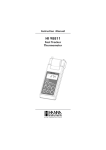
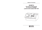
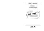
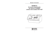
Instruction Manual
HI 88713
ISO Turbidity Meter
w w w. h a n n a i n s t . c o m
1
Dear Customer,
Thank you for choosing a Hanna Instruments product. This manual will provide you with the
necessary information for correct use of the instrument.
Please read this instruction manual carefully before using the instrument.
If you need additional technical information, do not hesitate to e-mail us at [email protected]
or see the back side of this manual for our worldwide sales and technical service contacts.
This instrument is in compliance with
directives.
TABLE OF CONTENTS
PRELIMINARY EXAMINATION ................................................................................................................... 3
GENERAL DESCRIPTION ........................................................................................................................... 3
ABBREVIATIONS ..................................................................................................................................... 4
PRINCIPLE OF OPERATION ...................................................................................................................... 4
FUNCTIONAL DESCRIPTION ..................................................................................................................... 6
SPECIFICATIONS ..................................................................................................................................... 8
GENERAL TIPS FOR AN ACCURATE MEASUREMENT .................................................................................... 9
START UP ............................................................................................................................................ 15
RANGE SELECTION ................................................................................................................................ 16
TUTORIAL MODE .................................................................................................................................. 16
HELP MODE .......................................................................................................................................... 17
MEASUREMENT PROCEDURE .................................................................................................................. 17
CALIBRATION PROCEDURE ..................................................................................................................... 20
GOOD LABORATORY PRACTICE (GLP) ...................................................................................................... 26
RESTORE FACTORY CALIBRATION ........................................................................................................... 26
LOG & LOG RECALL ............................................................................................................................... 27
SETUP ................................................................................................................................................. 28
PC INTERFACE ....................................................................................................................................... 30
ACCESSORIES ....................................................................................................................................... 31
WARRANTY ........................................................................................................................................... 31
RECOMMENDATIONS FOR USERS .......................................................................................................... 31
2
PRELIMINARY EXAMINATION
Please examine this Product carefully. Make sure the instrument is not damaged. If any damage has
occurred during the shipment, please notify your dealer.
This HI 88713 Turbidity bench meter is supplied complete with:
• Six Sample Cuvettes and Caps
• Calibration Cuvettes
• Silicone Oil
• Cloth for wiping the cuvettes
• AC/DC power adapter
• Instruction Manual
• Instrument Quality Certificate
Note:Save all packing material until you are sure that the instrument works correctly. Any
defective item must be returned in the original packing with the supplied accessories.
GENERAL
DESCRIPTION
GENERAL DESCRIPTION
The HI 88713 Turbidity bench meter is a high accuracy, meter that benefits from Hanna’s years of
experience as manufacturer of analytical instruments.
The HI 88713 Turbidity bench meter meets and exceeds the requirements of ISO 7027 standard.
The instrument is based on a state-of-the-art optical system which guarantees accurate results,
assures long term stability and minimizes stray light and color interferences. It also compensates for
variations in intensity of the LED, making no need for frequent calibration.
The 25 mm round cuvettes made from special optical glass guaranties reproductibility and consistency
of the measurements.
Turbidity measurements can be made in four modes: FNU (Formazin Nephelometric Units) ratio
mode FAU (Formazin Attenuation Units) NTU (Nephelometric Turbidity Units) NTU non-ratio mode.
Alternative EBC (European Brewery Comitee) measuring units are available wen measuring in NTU modes.
Normal measurement, continuous measurement or signal averaging measurement can be selected,
depending on the sample and desired accuracy.
A two, three, four or five-point calibration can be performed by using the supplied (<0.1, 15, 100,
750 FNU and 2000 NTU) standards, user prepared formar in standards can also be used in all
modes. Calibration points can be modified when they are used.
3
The HI 88713 Turbidity bench meter features G.L.P. (Good Laboratory Practice) functions that allow
traceability of the calibration conditions. The last calibration points as well as time and date
The HI 88713 Turbidity bench meter has a user-friendly interface with an easy to understand,
graphical LCD. Comprehensive contextual help is available at a simple key press. All messages and
help screens are available in several languages. Furthermore, a tutorial mode guides the user step by
step through the analysis process.
The HI 88713 features a logging function that can hold up to 200 measurements in the internal
memory. Data can be viewed directly on the screen or it can be downloaded to a PC for further
®
analysis using the HI9200 Windows compatible software.
ABBREVIATIONS
NTU
FAU
FNU
ISO
Nephelometric Turbidity Units
Formazin Attenuation Units
Formazin Nephelometric Units
International Organization for
Standardization
LCD
RTC
RH
ID
EBC
Liquid Crystal Display
Real Time Clock
Relative Humidity
Identification
European Brewery Comitee
PRINCIPLE OF OPERATION
Turbidity is the optical property that causes light to be scattered and absorbed, rather than transmitted.
The scattering of the light as it passes through a liquid is caused by the suspended solids. The higher the
turbidity, the greater the amount of scattered light. The molecules in a very pure fluid scatter light to a
certain degree, no solution will have zero turbidity.
The ISO 7027 Method specifies the key parameters for the optical system and the method to
measure the turbidity of water.
The HI 88713 Turbidity bench meter is designed to meet or exceed the criteria specified by the ISO
7027, DIN 38404 and NF EN 27027.
The light beam that passes through the sample is scattered in all directions. The intensity and pattern
of the scattered light is affected by many variables including the wavelenght of the incident light,
particle size and shape, refractive index and color.
The optical system of the HI 88713 turbidity bench meter uses an IR LED, a scattered light detector
(900) and a transmitted light detector (1800).
4
For the ratio turbidity mode, the microprocessor of the instrument calculates the NTU value, from the
signals that reaches the two detectors, by using an effective algorithm. The optical system and
measuring technique compensate the color interference and also the LED intensity fluctuations,
minimizing the need of frequent calibration.
For the FNU and NTU non ratio modes the turbidity is calculated from the signal that reaches the
scattered light detector (90°).
In FAU mode the turbidity is calculated from the signal that reaches the direct light detector, while
in NTU ratio mode the turbidity is obtained from signal ratio on scatter and transmitted light
detectors. The non ratio methods are more sensitive to the LED intensity fluctuations.
The lower detection limit of a turbidimeter is determined by the “stray light”. Stray light is the light that
reaches the detectors and is not caused by light scattering from suspended particles.
The optical system of HI 88713 instrument is designed to have very low stray light, providing accurate
results for low turbidity samples. However, special care must be taken when measuring low turbidities (see
page 9 “General Tips for an Accurate Measurement” for sample preparation and measuring techniques).
MEASUREMENT UNITS
The meter is using specific units according to the selected measurement mode. For NTU modes the
EBC unit option is available 1 EBC=0.245 NTU. When measuring in NTU modes a conversion to
EBC units is also available 0.245 NTU=1 EBC.
5
FUNCTIONAL DESCRIPTION
DISPLAY DESCRIPTION
The display contains the following fields:
INSTRUMENT DESCRIPTION
1)
2)
3)
4)
5)
Current time
Functional keys
Selected mode
Measuring units
Measured value
KEYPAD DESCRIPTION
The keypad contains 8 direct keys and 3 functional keys with the following functions:
Press to perform the function displayed above it. The function are screen releated.
ESC
RANGE
1)
2)
3)
4)
5)
6)
Liquid Crystal Display (LCD). The LCD has backlight for better visibility in dark environments.
Keypad. Splash proof resistant.
Cuvette Lid.
USB connector
12 Vdc power input
ON/OFF switch
6
Press to exit the current screen.
Press to access measurement modes.
Press to scroll up in a menu and help or to increment a set value.
LOG
Press to scroll down in a menu and help or to decrement a set value. Press
to log the current reading.
CAL
Press to access calibration menu.
RCL
Press to recall the log.
HELP
Press to display the help screen.
SETUP
Press to access the setup menu.
7
SPECIFICATIONS
FNU mode
Range
Resolution
Accuracy
FAU mode
Range
Resolution
Accuracy
NTU ratio mode
Range
Resolution
Accuracy
NTU non ratio mode
Range
Resolution
Accuracy
Range selection
Repeatibility
Stray Light
Light Detector
Method
Measuring mode
Turbidity Standards
Calibration
Light Source
Lamp life
Display
LOG Memory
Serial Interface
Environment
Power supply
Dimensions
Weight
0.00 to 9.99; 10.0 to 99.9; 100 to 1000 FNU
0.01; 0.1; 1 FNU
±2% of reading plus straylight
10.0 to 99.9; 100 to 4000 FAU
0.1; 1 FAU
±10% of reading
0.00 to 9.99; 10.0 to 99.9; 100 to 4000 NTU
0.00 to 9.99; 10.0 to 99.9; 100 to 980 EBC
0.01; 0.1; 1 NTU
0.01; 0.1; 1 EBC
±2% of reading plus straylight
±5% of reading above 1000 NTU
0.00 to 9.99; 10.0 to 99.9; 100 to 1000 NTU
0.00 to 9.99; 10.0 to 99.9; 100 to 245 EBC
0.01; 0.1; 1 NTU
0.01; 0.1; 1 EBC
±2% of reading plus straylight
Automatic
±1% of reading or straylight, whichever is greater
< 0.1 NTU (0.05 EBC)
Silicon Photocell
ISO 7027 Method
Normal, Average, Continuous.
<0.1, 15, 100, 750 FNU and 2000 NTU
Two, three, four or five-point calibration
IR LED
Instrument life
40 x 70mm graphic LCD (64x128 pixels) with backlight
200 records
USB
0°C (32°F) to 50°C (122°F); max 95% RH non-condensing
12 Vdc power input
230 x 200 x 145 mm (9 x 7.9 x 5.7”) L x W x H
2.5 Kg (88 oz.)
8
GENERAL TIPS FOR AN ACCURATE MEASUREMENT
The HI 88713 is a highly accurate bench too turbidity meter. Special care must be taken during
calibration and sample preparation to optimize the instrument performance and to fully benefit from
its features. Is very important for the analyst to use proper measurement techniques for accurate,
precise and repeatable readings. The instructions listed below should be carefully followed during
calibration and measurement to ensure optimum accuracy.
GENERAL RULES
• Always put the instrument on a flat, rugged surface when taking measurements.
• Do not operate in direct sunlight.
• Keep the lid of the instrument closed when it is not used to prevent dust or dirt entering inside.
• Always close the cuvette lid during measurement.
• Always use cuvettes without scratches or cracks because they can cause inaccurate readings.
• Always cap the cuvettes to prevent the sample from spilling
• To prevent contamination of the optical system, do not use to much oil.
• When using multiple cuvettes, they should be indexed and matched, when possible.
CUVETTE
The cuvette is part of the optical system in all measurements. The light reaches the sample by
passing through the cuvette glass. As a result, the measurement can be affected by the glass
imperfections, dirt, dust, scratches, or fingerprints present on the cuvette surface. Special care
must be taken in preparing and handling the cuvette.
Note: If you are using multiple cuvettes, always match the cuvettes.
CUVETTE HANDLING
The cuvettes should be free of scratches or cracks. Any cuvette with visible scratches should be
discarded. The cuvettes should be periodically washed with acid. After washing, the cuvettes
should be rinsed well with distilled or deionized water, multiple times. Allow cuvettes to air-dry
and store them for long periods of time with theire caps, to avoid dirt entering inside. Always
handle the cuvette by touching only the cap or its top side (over the horizontal line).
Always store the cuvettes in separate boxes or with separators between them to avoid scratches
on the surface.
CUVETTE PREPARATION
Whenever a cuvette is used, it must be clean inside and outside. When it is placed into the
instrument, it must be dry outside, completely free of fingerprints or dirt.
9
CUVETTE PREPARATION
Whenever a cuvette is used, it must be clean inside and outside. When it is placed into the
instrument, it must be dry outside, completely free of fingerprints or dirt.
To further reduce the effect of glass imperfections, the cuvette can be indexed and use this new index as the position mark.
For indexing one cuvette or matching multiple cuvettes, the continuous reading mode is suggested.
In this mode multiple successive readings are taken without turning off the lamp. The turbidity is
immediately displayed, reducing considerably the measurement time.
Note: The instrument can not perform continuous readings if the average mode is on.
In order to index a cuvette follow the next steps:
• Fill the cuvette with high quality water (<0.1
FNU) up to the 10 mL mark.
If the cuvette is not indexed, use the factory marking to align the cuvette with the marking on the
cuvette holder.
CUVETTE OILING
To hide minor imperfections and scratches, the cuvettes should be oiled outside with the supplied silicone
oil. This is very important, especially for low turbidity samples (< 1 FNU), otherwise scratches can
contribute and alter turbidity readings.
The silicone oil has the same refractive index as the glass and will not alter the turbidity readings. It is
important to apply only a thin layer of silicone oil.
Warning: Do not apply silicone oil in excess because it may retain dirt or contaminate the cuvette
holder of the instrument, altering the turbidity readings.
It is very important to apply the silicone oil on a clean, dry cuvette. Apply a few drops of oil and wipe
the cuvette thoroughly with a lint-free cloth. Wipe off the excess oil till you obtain a thin, uniform
layer. If the procedure is correctly followed, the cuvette should appear nearly dry with no visible oil.
• Clean and oil the cuvette as described in the
previous section.
• Turn the instrument ON.
• Insert the cuvette into the instrument and press
“Read” functional key. Record the reading.
Note: The supplied cloth for oiling should be stored together with the silicone oil bottle and
cuvettes, taking care to avoid contamination with dirt. After a few oiling procedures, the cloth
will contain enough oil to wipe the bottle with it without adding more oil. From time to time
add some drops of oil on the cuvette to provide the necessary oil quantity in the cloth.
• Open the instrument lid, slightly rotate the cuvette and take a new reading.
INDEXING A CUVETTE
It is very important for low turbidity readings to always insert the cuvette into the instrument in the same position.
All cuvettes are factory indexed. The factory mark on the cuvette can be used to align the cuvette with
sign on the cuvette holder.
• Repeat the previous step until you read the lowest value.
• Alternatively, press and hold the “Read” key to make continuous readings. After the first value
is displayed, open the lid and start rotating the cuvette until the lowest value is displayed.
10
11
• Mark this position on the white band at the top of
the cuvette with a water resistant pencil.
• Always use this position to align the cuvette
with the mark on the cuvette holder.
MATCHING MULTIPLE CUVETTES
Precise measurements require the use of a single cuvette. If it is not possible, cuvette selection
and matching must be performed before taking measurements.
In order to match multiple cuvettes follow the next
steps:
• Fill multiple cuvettes with high quality water
(<0.1FNU) up to the 10 mL mark.
• Clean and oil the cuvettes as described before.
• Turn the instrument ON.
• Insert the first cuvette into the instrument and
press “Read” functional key. Record the
reading.
• Open the instrument lid, slightly rotate the
cuvette and take a new reading.
• Repeat the previous step until you read the
lowest value.
• Mark this position on the white band at the top
of the cuvette with a water resistant pencil.
12
• Insert the second cuvette into the instrument and
take a reading.
• Open the instrument lid, slightly rotate the
cuvette and take a new reading.
• Repeat the last step for the second cuvette until the reading is within 0.01 FNU of the value obtained for the first cuvette.
• Alternatively, press and hold the “Read” functional key, after the first value is displayed, open
the lid and start rotating the cuvette until the read value matches the first cuvette.
• Mark this position on the second cuvette with a water resistant pencil.
• Follow the same procedure for all the cuvettes you need.
Note: If the cuvette is indexed, use the index to position it in the instrument.
SAMPLING TECHNIQUE
When taking turbidity measurements it is very important to select a representative sample. For
consistent results, follow the next tips when sampling:
• Gently mix the water before taking the sample.
• If the sample is taken from a pipe, discard the first few liters.
• If measuring a non uniform source, collect samples from different places and mix them.
When measuring the collected sample, keep in mind the following:
• Samples should be analyzed immediately after collection because the turbidity can change in time.
• To avoid dilution of the sample it is better to rinse the cuvette with a quantity of sample and then
discard. Then you can fill the cuvette with sample.
• Pay attention that cold samples do not condense on the sample cell.
REMOVING AIR BUBBLES
Any air bubbles present in the sample will cause high turbidity readings. To obtain accurate
measurements, remove the air bubbles using one of these methods:
• Application of a partial vacuum;
• Addition of a surfactant, such as Triton X-100;
13
• Use of an ultrasonic bath;
• Heating the sample.
Sometimes it is necessary to combine two or more methods for efficient air bubble removal.
Note: Each method can alter the sample turbidity, if misused, so they have to be used with caution.
APPLICATION OF VACUUM
Vacuum works by decreasing the atmospheric pressure. The bubbles from the solution come out to
the surface. Application of vacuum is a very simple procedure andany vacuum can be used. The
simplest equipment is a syringe and a rubber stopper.
Notes: • Pay attention that the vacuum equipment be clean and oil-free.
• It is not recommended to apply vacuum to a viscous sample that contains volatile
components. The vacuum can disrupt the volatile components and increase the bubbles
in the sample.
ADDITION OF SURFACTANT
Surfactant changes the surface tension of the water. This causes the bubbles to be released from the
sample. This method is effective for samples that are supersaturated with air.
The procedure consists in the addition of a drop of surfactant in the cuvette before adding the sample
to be analyzed.
A common surfactant used for degassing is Triton X-100.
Warning: Changing the surface tension will cause a rapid settling of particles that cause turbidity.
To avoid this problem, analyze the sample as soon as possible.
Do not shake the sample vigorously because the surfactant may foam. Always rinse the cuvette before
adding a new sample to avoid surfactant accumulation.
Surfactant contribution to the turbidity readings is negligible.
Note: Surfactant addition should be used for degassing only when other methods are ineffective.
USE OF AN ULTRASONIC BATH
The ultrasonic waves are very effective in removing air bubbles from samples. However, ultrasonic
waves should be used with care because they can alter the samples turbidity characteristics, by
modifying the shape and size of particles which cause turbidity. The ultrasonic waves can also break
the existing air bubbles, leading to a complication in the degassing process.
In order to avoid excess application of the ultrasonic waves use the ultrasonic bath until all visible air
bubbles are removed, and then measure the turbidity. This is the most used procedure for degassing.
If you are not sure that all air bubbles were removed, apply ultrasonic waves again for a short period
of time and then measure the turbidity. Repeat this procedure until the turbidity is increasing instead
of decreasing, sign that turbidity of the sample was altered.
In order to degas a sample, fill a clean cuvette with sample and immerse it (1/2 to 2/3 immersed)
in an ultrasonic bath. Follow the degassing procedure described above. Only after the degassing
procedure is finished the cuvette can be capped.
14
HEATING THE SAMPLE
This procedure can be very effective however it should be handled with care because it can alter the
turbidity of the sample. When heating a sample, the volatile components from the sample can
vaporize, the suspended components can dissolve or the sample characteristics can change.
The heating procedure should be used with extreme care.
Use a warm water bath and immerse the cuvette filled with sample into the bath. Heat the sample
only until the visible bubbles are removed.
Note: Always cool the heated sample to the original temperature before measurement.
The heating procedure can be used in combination with vacuum or ultrasonic waves application for
a more effective air bubble removal.
STARTUP
The HI 88713 Turbidity bench meter is supplied with all necessary accesories
Unpack the instrument and place it on a flat surface. Do not place the instrument in dirrect sunlight.
Insert the 12 Vdc power plug into its input on the back of the instrument.
Switch on the instrument. On the LCD, the Hanna Logo will appear for a short time, followed by the
main screen for turbidity measurements.
The instrument loads the selected language. If no language can be loaded the instrument will work
in the “safe mode”. In “safe mode” all the messages are displayed in English and
tutorial and help information are not available.
15
RANGE SELECTION
The HI 88713 bench-top Turbidity meter has four
measuring modes: FNU, FAU, NTU Ratio and NTU
Non Ratio. When the instrument is in the main
screen, the selected mode is displayed in the right
side of the LCD, on the message line.
To change the mode, press the RANGE key.
When the display shows the Change mode screen,
use the UP or DOWN key to select a new mode .
Press “CFM” key to select the new mode. The
instrument returns to the main screen.
TUTORIAL MODE
The HI 88713 bench-top Turbidity meter has a unique Tutorial Mode that provides additional
information to help the unexperienced user during the measurements. The instrument displays a screen,
with explanations and confirmation button, when a preparation or other operation has to be performed
by the operator. The instrument resumes the measuring sequence when the operator confirms that the
requested operation was done.
To disable this mode, when in the main screen,
press the SETUP key to enter the setup, and then
press DOWN key until the “Tutorial” line is
highlighted. Press the “Disable” key then press
ESC to return to the main screen.
HELP MODE
The HI 88713 bench-top Turbidity meter offers an interactive contextual help that assists the user
at any moment.
To access help screens, just press HELP.
A screen with additional information will appear.
To read all available information, scroll down or
up text using the UP or DOWN key.
Press the “Support” key to access a list of the
Hanna support centers and their contact information.
Press the “Accessories” key to view a list of the
instruments accessoies.
To exit support or accessories screens, press ESC, and
the instrument will return to the previous help screen.
To exit help mode just press the HELP key again
and the meter will display the previous screen.
MEASUREMENT PROCEDURE
When taking turbidity measurements, several basic rules should be followed:
• Always use cuvettes without scratches or cracks because they can cause inaccurate readings.
• Always cap the cuvettes to prevent spillage of the sample from spilling the instrument.
• Always close the cuvette cover during measurement.
• To prevent contamination of the optical system, do not use too mush silicon oil.
To take turbidity measurements:
• Turn the instrument ON by pressing ON/OFF.
When dashes are displayed on the LCD, the
instrument is ready. The current time appears in
the upper left corner of the display and the
mode name appears on the right side of the
LCD, in the message line.
• Fill a clean, dry cuvette with 10 mL of sample up to
the mark, only handle the cuvette by the top.
16
17
• Replace the cap.
• Wipe the cuvette thoroughly with a lint-free
cloth to remove any fingerprints, dirt or water
spots.
• Apply silicone oil on the cuvette and wipe with
a lint-free cloth to obtain an even film over the
entire surface of the cuvette.
Note: It is very important to oil the cuvette, especially for low turbidity values (< 1 FNU)
to hide the glass imperfections which can
influence the reading.
• Place the cuvette into the instrument. Align the
mark from the cuvette with the sign on the
instrument top
• Close the lid.
Note: If you have a cuvette with indexing mark,
place the cuvette into the instrument with
the indexing mark aligned with the sign on
the instrument top.
NORMAL MEASUREMENT
This type of measurement is best suited for regular readings, when the sample is stable and normal
accuracy is required. In normal mode, the measurement takes about 10 seconds and the lamp is ON
for a minimum period of time (about 7 seconds).
• Press “Read” functional key to take the
measurement.
The display will show “READ” in the left side
and blinking dashes. The dashes and light icon
will appear during different measurement
phases.
• The result is displayed in the selected units.
CONTINUOUS MEASUREMENT
This measurement mode is suitable when many measurements have to be taken in a short period of
time. The mode is useful to evaluate a very fast settling sample. This measurement mode is
recommended for indexing cuvettes.
18
• Press “Read” functional key and keep it pressed to take continuous readings.
The display will show “READ” in the left side and blinking dashes. The dashes and light icon will
appear during different measurement phases. The first value is displayed after 10 seconds and then
a new reading is displayed each second as long as the “Read” functional key is kept pressed. When
a new value is displayed, the measurement value will briefly blink.
The last value remains on the display after the “Read” functional key is released.
AVERAGED MEASUREMENT
This measurement mode is useful when samples that cause unstable readings are analyzed. By
averaging several readings, noise effect is reduced and accurate measurements can be taken.
This mode can also be selected when high accuracy measurements are needed. In the average mode
10 measurements are averaged in a short period of time (about 20 seconds).
To use the averaged reading mode first enter setup and enable the Average reading mode. The “AVG”
text will be displayed in the left side of the screen.
• Press “Read” functional key to take the
measurement.
The display will show “READ” in the left side and
blinking dashes. The dashes and light icon will
appear during different measurement phases. The
first value is displayed after 10 seconds and then a
new average of the available readings is displayed
each second. When a new value is displayed, the
measurement value will blink briefly. The last averaged
value remains on the display at the end of the
measurement.
The HI 88713 Turbidity bench meter automatically
selects the correct turbidity range to display the
results with the highest accuracy. In FNU and NTU
Non-Ratio Turbidity Modes, if the measured value
is higher than 1000 FAU, the display will show
the maximum value blinking and the message “Out
of range” on the message line. For FAU Turbidity
and NTU Ratio Turbidity modes, if the measured
value is higher than 4000 FNU/NTU (980 EBC),
the display will show the maximum value blinking
and the message “Out of range” on the message
line.
19
UNITS CHANGE (only for NTU Ratio and NTU Non-Ratio modes)
To change the units for NTU Ratio and Non-Ratio modes, simply press the “Unit” functional key
when a measurement is available. The EBC value is obtained by multiply with 0.245 the NTU value.
CALIBRATION PROCEDURE
The HI 88713 Turbidity bench meter is supplied with 5 AMCO Hanna standards (<0.1 FNU, 15 FNU,
100 FNU, 750 FNU and 2000 NTU) that are specially designed for NTU ratio mode.
The calibration can be done using the supplied calibration solutions for NTU Ratio mode or
user prepared standards for all modes. Turbidity standards have a shelf life and should not be
used after the expiration date. Alternatively, formazin standards can be used. It is recommended
that the turbidity value of the prepared calibration solutions to be close to the default
calibration points.
The first calibration point should be near 0 FNU, the second point can be chosen between 10 and
20 FNU, the third point between 50 and 150 FNU, the fourth point between 600 and 900 FNU and
the fifth point between 1500 and 2500 NTU.
FORMAZIN PREPARATION
In order to prepare formazin 4000 NTU stock solution, follow the next procedure:
Solution I : Dissolve 1.000 gram of hydrazine sulfate, (NH2)2 H2SO4, in distilled, deionized water
and dilute to 100 mL in a volumetric flask.
Warning: Handle hydrazine sulfate with care because it is a carcinogen reagent. Avoid inhalation,
ingestion, or skin contact. Formazin solution can also contain some hydrazine traces.
Solution II : Dissolve 10.000 grams of hexamethylenetetramine, (CH2)6 N4, in distilled, deionized
water and dilute to 100 mL in a volumetric flask.
Stock solution: Mix 10 mL Solution I and 10 mL Solution II in a flask. Let the stock solution stays
48 hours at 25±3°C (77±5°F). This will result in a 4000 NTU formazin suspension. It is very
important for the formation of the formazin polymer to maintain the same temperature.
The stock solution (4000 NTU) can be stored up to one year in proper conditions. Store formazin in
amber glass bottle or any UV-light blocking bottle.
To obtain a high quality formazin always use pure reagents and high-purity water.
To prepare the calibration standards, dilute the stock solution with the same high-purity water you
used for the preparation of the stock solution. The diluted formazin solutions are not stable. They
should be used immediately after preparation and discard immediately after use.
20
CALIBRATION
For best results, the measurement techniques must be followed during calibration. If formazin
standards are used, mix the cuvettes gently for about 1 minute and then allow the standard to settle
for 1 more minute before calibration.
Calibration can be performed in up to five points, independently, for each mode. The calibration
points are:
FNU mode:
0, 15, 100, 750
FNU
FAU mode:
15, 100, 750, 2000 FAU
NTU ratiometric mode:
0, 15, 100, 750, 2000 NTU
NTU non-ratiometric mode: 0, 15, 100, 750
NTU
Before making the calibration, assure that you are in the correct mode.
To enter calibration, press CAL key while in main screen. The first screen of GLP
information is displayed. Press “Cal” functional key to start calibration.
It is possible to interupt calibration procedure at any time by pressing CAL or ESC key.
FIRST POINT CALIBRATION
• The first calibration point is displayed on the LCD.
This point is used for FNU and NTU modes to check the quality of the water used for dilution and to
confirm that the optical system is not dirty. In this case, if the value of the first point is over 0.15 FNU
(NTU), a warning “Cal Point1 high !” is displayed when the calibration is saved and a warning “Out of
calibration range” is displayed when measurements under 10.0 FNU (NTU) are performed.
21
Note: The reading of the first point could be skipped for FNU and NTU modes by pressing “Skip”
functional key. In this case, the 0.00 value will be used for calibration.
• Place the cuvette for first calibration point:
• <0.1 FNU (NTU) calibration cuvette for all
modes except FAU mode.
• 15 NTU formazin prepared standard for FAU
mode.
Note: For the FAU mode, if necessary, press UP
or DOWN key to edit the calibration point value
to match the exact value of the standard.
• Close the lid and press “Read” functional key. The display will show the value blinking and the
light icon during measurement.
Note: If the Average mode was previously selected, the measurement in calibration mode will be
done using the average.
• At the end of the measurement, the second proposed calibration point is displayed.
SECOND POINT CALIBRATION
• Remove the first calibration cuvette.
• Place the cuvette for second calibration point:
• 15 NTU (FNU) calibration cuvette for NTU
ratiometric mode.
• 15 NTU formazin prepared standard for NTU
non-rating and FNU modes.
• 100 NTU formazin prepared standard for FAU mode.
• If the calibration is terminated, the display will briefly
show “Store...” and the two point calibration is saved.
The instrument returns to the main screen.
THIRD CALIBRATION POINT
• Remove the second standard cuvette.
• Place the cuvette for third calibration point:
• 100 FNU (NTU) calibration cuvette for NTU
ratiometric mode.
• 100 NTU formazin prepared standard for NTU
non-ratio and FNU modes.
• 750 NTU formazin prepared standard for FAU mode.
Note: If necessary, press UP or DOWN key to edit each
calibration point value to match the exact value of the
standard as measured with a reference turbidimeter.
• Close the lid and press “Read” functional key.
The display will show the value blinking and the light icon during measurement.
• At the end of the measurement, the fourth proposed calibration point is displayed.
• At this moment it is possible to exit calibration by pressing “End” functional key.
• If the calibration is terminated, the display will briefly
show “Store...” and the three point calibration is saved.
The instrument returns in the main screen.
Note: If necessary, press UP or DOWN key to edit
each calibration point value to match the exact value of
the standard as measured with a reference turbidimeter.
• Close the lid and press “Read” functional key.
The display will show the value blinking and the light icon during measurement.
• At the end of the measurement, the third proposed calibration point is displayed.
• At this moment it is possible to exit calibration by pressing “End” functional key.
22
23
FOUR-POINT CALIBRATION
• Remove the third standard cuvette.
• Place the cuvette for third calibration point:
• 750 FNU (NTU) calibration cuvette for NTU
ratio mode.
• 750 NTU formazin prepared standard for NTU
non-ratio and FNU modes.
• 2000 NTU formazin prepared standard for FAU
mode.
Note: If necessary, press UP or DOWN key to edit the calibration point value to match the exact value of
the standard as measured with a reference turbidimeter.
• Close the lid and press “Read” functional key. The display will show the value blinking and the
light icon during measurement.
• At the end of the measurement, the calibration
is saved and the display will briefly show “Store...”.
The instrument returns in the main screen.
CALIBRATION ERROR MESSAGES
If the value of the standard read during the calibration is too far from the set value, the instrument
will display a standard low or a standard high message.
Note: If necessary, press UP or DOWN key to edit each calibration point value to match the exact value
of the standard as measured with a reference turbidimeter.
• Close the lid and press “Read” functional key. The display will show the value blinking and the
light icon during measurement.
• The “Store...” message is displayed for FAU, FNU and NTU non-ratio modes and the calibration
is saved. The instrument returns to the main screen.
• The fifth proposed calibration point, 2000 NTU for NTU Ratio mode, is displayed.
• At this moment it is possible to exit calibration by pressing “End” functional key.
• If the calibration is terminated, the display will
briefly show “Store...” and the four point calibration
is saved. The instrument returns in the main screen.
FIFTH CALIBRATION POINT (NTU Ratio Turbidity only)
• Remove the fourth standard cuvette.
• Place the 2000 NTU calibration cuvette (or the
fifth prepared formazin standard) into the holder,
with the cuvette mark aligned to the sign on the
instrument top.
24
Check if the correct standard is used or prepare a fresh standard, if formazine is used, and repeat the
reading of the standard.
If the calculated calibration coefficients are outside a
certain range a calibration error message is displayed.
OUT CAL RANGE FUNCTION
The instrument has a mechanism to prevent taking
measurements in a range where the calibration
does not assure the best results. The message
“Out of Calibration Range” is displayed on the
message line in the following situations:
• When the first calibration point is over 0.15 FNU and the reading is under 10 FNU.
• When two point calibration was performed and the reading value is over 40 FNU.
• When a three point calibration was performed and the reading is over 150% of the the third point value.
• When a four point calibration was performed and the reading is over 200% of the the fourth point value.
25
GOOD LABORATORY PRACTICE (GLP)
LOG AND LOG RECALL
The HI 88713 Turbidity bench meter has a built in complete GLP information. The calibration date
and the calibration points are displayed in a comprehensive mode for each range.
To display the GLP information, simply press CAL key. A screen with instrument serial number and
with information about the calibration is displayed. For further information, press the “GLP”
functional key.
The HI 88713 Turbidity bench meter has a powerful log function that could store up to 200 records.
Each record contains:
• the measuring mode,
• the reading value,
• the measuring unit,
• the date and time of the measurement,
• the current log number.
Notes: • The log can be saved only after a measurement is completed.
• A measurement can be saved only once.
LOG SAVE
To log a record, simply press LOG key after the
measurement is completed. A record number is
assigned to each logged measurement. Each
reading can be stored only once.
LOG RECALL
The log can be consulted at any time by simply
pressing RCL key.
To exit log consulting, press RCL key again.
The log content is displayed one record at a time,
starting with the most recent one. The information
regarding one record is displayed in one screen.
To browse the log press the UP or DOWN key.
LOG DELETE
The last log or all logs can be deleted.
To delete the last log, simply press “Delete” functional key when the last log is displayed. The log
will be deleted and the next log is immediately displayed.
To delete all logs, press “DelAll” functional key. A
confirmation screen is displayed. Press “CFM”
functional key to confirm the action. The log will be
deleted and the instrument returns in the main screen.
Note: The records for all parameters are deleted
when this action is performed.
The GLP contains:
• Instrument serial number
• The last user calibration date, in
selected format and time in hh.mm format. If no
calibration was performed, the “Not calibrated”
message is displayed and the meter uses only the
factory calibration.
• Parameter as NTU Ratio Turbidity, NTU
Non Ratio Turbidity, FAU Turbidity or FNU Turbidity.
• The value of each calibration point (up to
5 points for NTU ratio mode; 4 points for FNU, FAU
and NTU non-ratio modes). If the first calibration
point was skipped, the 0.00 value is displayed.
RESTORE FACTORY CALIBRATION
To restore the factory calibration for the currently
selected range, press CAL key when in the main
screen. The first screen for the GLP is displayed.
Press “Delete” functional key to initiate the
calibration delete procedure and then press “CFM”
functional key to delete the user calibration and
restore the Factory calibration.
Note: Only the user calibration for the current
selected range is deleted.
26
27
SETUP
The instrument’s parameters can be changed in the Setup mode. Some parameters affect the measuring sequence
and others are general parameters that change the behaviour or appearence of the instrument.
The setup mode may be accessed from the main screen by pressing the SETUP key.
Press ESC or SETUP to return to the main screen.
A list of setup parameters will be displayed with currently
configured setting. Press HELP for aditional information.
Press the UP or DOWN key to select the parameter
and depending to the parameter type, select the
new value as follows.
Backlight
Values: 0 to 8.
Press “Modify” functional key to access the backlight value.
Use the “Right” or ”Left” functional key (alternatively,
the UP or DOWN key) to increase or decrease the
display backlight.
Press “Accept” functional key to confirm or ESC to return to
the setup menu without saving the new value.
Contrast
Values: 0 to 20.
This option is used to set the display’s contrast.
Press “Modify” functional key to change the display’s contrast.
Use the “Right” or ”Left” functional key (alternatively,
the UP or DOWN key) to increase or decrease the value.
Press “Accept“ functional key to confirm the value or ESC to
return to the setup menu without saving the new value.
Average
Option: Enabled or Disabled.
This option is used to enable/disable averaged measuring
mode. If enabled, the instrument takes 10 readings and
display the resulting average value. The partial average is
displayed during measurement.
Press the “Enable” functional key to enable or disable this
option.
28
Date / Time
This option is used to set the instrument’s date and time.
Press “Modify” to change the date/time.
Press “Left” or ”Right” functional key to highlight the
value to be modified (year, month, day, hour, minute or
second). Use the UP or DOWN key to change the value.
Press “Accept” functional key to confirm the new value
or ESC to return to the setup without saving the new
time or date .
Time format
Option: AM/PM or 24 hours.
Press the “AM/PM” functional key to select the
new value.
Date format
Press “Modify” functional key to change the Date
Format.
Use the UP or DOWN key to select the desired format.
Press “Accept” functional key to confirm the value
or ESC to return to the setup menu without saving
the new format.
Language
Option: English, Italiano or Español
Press the corresponding function key to change the
option.
If the new selected language cannot be loaded,
the previously selected language will be reloaded.
Tutorial
Option: Enabled or Disabled.
This option is used to enable/disable tutorial mode.
If enabled this option will provide the user short
guides on the screen.
Press the “Enable” functional key to select this option.
29
Beeper
Option: Enabled or Disabled.
This option is used to enable/disable the beeper.
Press the “Enable” functional key to enable or
disable this option.
When enabled, a short beep is heard every time a
key is pressed.
A long beep alert sounds when the pressed key is
not active or an error condition is detected.
Instrument ID
Option: 0 to 9999.
This option is used to set the instrument’s ID
(identification number). The instrument ID is used
while exchanging data with a PC.
Press “Modify” functional key to access the
instrument ID screen. Press the UP or DOWN key
in order to set the desired value. Press “Accept”
functional key to confirm the value or ESC to return
to the setup menu without saving the new value.
Meter information
Press “Select” functional key to view the Instrument
model, firmware version, language version and
instrument serial number.
Press ESC to return to the Setup mode.
ACCESSORIES
REAGENT SETS
HI 93703-58
HI 88713-11
Silicon oil (15 mL)
Calibration set for turbidimeter(<0.1, 15, 100 750 FNU and 2000 NTU)
OTHER ACCESSORIES
HI 731318
HI 731331
HI 731335N
HI 92000
HI 93703-50
Tissue for wiping cuvetets (4 pcs.)
Glass cuvettes (4 pcs.)
Caps for cuvettes (4 pcs.)
Windows® compatible software
Cuvettes cleaning solution (230 mL)
WARRANTY
HI 88713 is warranted for two years against defects in workmanship and materials when used for
its intended purpose and maintained according to the instructions.
This warranty is limited to repair or replacement free of charge.
Damage due to accident, misuse, tampering or lack of prescribed maintenance is not covered.
If service is required, contact your dealer. If under warranty, report the model number, date of purchase,
serial number and the nature of the failure. If the repair is not covered by the warranty, you will be notified
of the charges incurred.
If the instrument is to be returned to Hanna Instruments, first obtain a Returned Goods Authorization
Number from the Customer Service Department and then send it with shipment costs prepaid. When
shipping any instrument, make sure it is properly packaged for complete protection.
To validate your warranty, fill out and return the enclosed warranty card within 14 days from the date of purchase.
RECOMMENDATIONS FOR USERS
Log data download from the instrument to the PC can be done with the HI 92000 Windows compatible
software (optional). HI 92000 also offers graphing and on-line help features. Data can be exported to the
most popular spreadsheet programs for further analysis.
To connect your instrument to a PC, use a standard USB cable. Make sure that your instrument is switched
off. Plug one connector to the instrument’s USB socket and the other to the USB port of your PC.
Please reffer to the HI 92000 software to download the data from the instrument.
Before using this product, make sure that it is entirely suitable for your specific application and
for the environment in which it is used.
Operation of this instrument may cause unacceptable interferences to other electronic equipments,
requiring the user to follow all necessary steps to correct interferences.
Any variation introduced by the user to the supplied equipment may degrade the instrument’s
EMC performance.
To avoid damage or burns, do not put the instrument in microwave ovens. For your own and the
instrument safety do not use or store the instrument in hazardous environments.
30
31
PC INTERFACE
SALES AND TECHNICAL SERVICE CONTACTS
Australia:
Tel. (03) 9769.0666 • Fax (03) 9769.0699
China:
Tel. (10) 88570068 • Fax (10) 88570060
Egypt:
Tel. & Fax (02) 2758.683
Germany:
Tel. (07851) 9129-0 • Fax (07851) 9129-99
Greece:
Tel. (210) 823.5192 • Fax (210) 884.0210
Indonesia:
Tel. (210) 4584.2941 • Fax (210) 4584.2942
Japan:
Tel. (03) 3258.9565 • Fax (03) 3258.9567
Korea:
Tel. (02) 2278.5147 • Fax (02) 2264.1729
Malaysia:
Tel. (603) 5638.9940 • Fax (603) 5638.9829
Singapore:
Tel. 6296.7118 • Fax 6291.6906
South Africa:
Tel. (011) 615.6076 • Fax (011) 615.8582
Taiwan:
Tel. 886.2.2739.3014 • Fax 886.2.2739.2983
United Kingdom:
Tel. (01525) 850.855 • Fax (01525) 853.668
MAN88713
05/08
Thailand:
Tel. (662) 619.0708 • Fax (662) 619.0061
USA:
Tel. (401) 765.7500 • Fax (401) 765.7575
For e-mail contacts and a complete list of Sales and Technical offices, please see
www.hannainst.com.
32