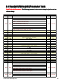
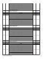
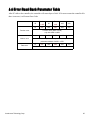
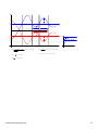
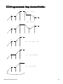
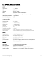
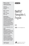
1
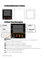
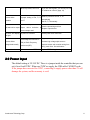
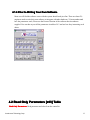
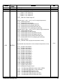
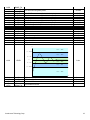
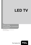
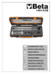
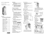
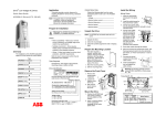
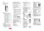
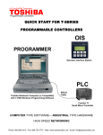
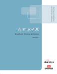
ATEC302
TE Temperature Controller
Reference Manual
Rev 1.5
May. 2011
Accuthermo Technology Corp.
Table of Content
1.
2.
Introduction..................................................................................................................4
1.1 Using Manuals....................................................................................................... 5
System Overview......................................................................................................... 6
2.1 System Configuration Overview........................................................................... 6
2.2 Panel Dimension & Cutout....................................................................................7
2.3 Front Panel Description......................................................................................... 7
2.4 Back Panel Wiring Diagram.................................................................................. 8
2.5 USB Wiring & Color Code....................................................................................8
2.6.1 Sensor Type & Measurement Range.................................................................. 8
2.6.2 Sensor Type & Dip-switch setting...................................................................... 9
3.
2.7 Menu (Parameters) Overview..............................................................................10
2.8 Error Message & Troubleshooting.......................................................................10
2.9 Power Input..........................................................................................................11
Front Panel Operation................................................................................................ 12
3.1 Push Buttons
i.
ii.
................................................................... 12
Return to Top Level Display......................................................................12
Go to Menu Mode......................................................................................12
iii. Select Parameters in Menu........................................................................ 12
iv. Changing Parameter value......................................................................... 13
3.2 Power UP Display Sequence............................................................................... 13
4.
3.3 Change the SV (Set Value) Number.................................................................... 13
Parameters Description.............................................................................................. 13
4.1 Communication Protocol..................................................................................... 13
4.1.1 Communication Method........................................................................... 13
4.1.2 Communication Protocol Format............................................................. 14
4.1.3 Communication Read/Write Format.........................................................14
4.1.4 Prior to Writing Your Own Software........................................................ 17
4.2 Read Only Parameters [x03] Table...................................................................... 17
4.3 Read[x03]/Write[x06] Parameter Table...............................................................21
4.4 Error Read Back Parameter Table....................................................................... 25
5. Control Method..............................................................................................................26
5.1 PID Control:.........................................................................................................26
5.2 Auto-tune Function:............................................................................................. 26
5.3 Programmable Step Control Profile:................................................................... 28
5.4 Alarm Function:................................................................................................... 29
Accuthermo Technology Corp.
2
6. SPECIFICATIONS........................................................................................................ 30
Accuthermo Technology Corp.
3
1. Introduction
This manual contains information for the installation, operation and tuning of your Accuthermo ATEC302
TE Panel Temperature Controller, ATEC402 Din-Rail TE Temperature Controller and FTX700 High
Power TE Amplifier/Driver. ATEC302 can also be connectted to FTX300 or FTX100 H-bridge amplifiers.
ATEC302
TE Panel Controller
ATEC402
TE Din-rail Controller
FTX700D
TE Amplifier/Driver
Pic
Pic
Pic
The Accuthermo microprocessor controllers are FUZZY ENHANCED “proportional + integral +
derivative” (PID) controllers that come in with industry standard DIN72x72mm and Din-Rail size. The
input is configurable and allows selection of input between thermocouples, RTD and Thermistor*.
The TE Amplifier is capable of running up to 700Watt of power. It is a very efficient TE power amplifier.
The amplifier can run without force air (fan) under 350Watt in ambient condition. Over 350Watt, it is
recommended to add in fan for proper ventilation.
The controller can talk to PC through a dedicated USB cable or a RS232 communication daughter card
(option) that Accuthermo provides. And it comes with very sophisticated PC software for FREE.
The controllers can also be serial linked together and talk to one PC by using RS-485 communication
method (option).
Caution: When USB cable is connected to the controller, the RS232 or RS485 communication daughter
card should not be plugged inside the controller. Otherwise, it will have conflict.
Accuthermo Technology Corp.
4
1.1 Using Manuals
There are three manuals for this system:
Reference Manual (this one): The manual is designed for user who wants to use the front panel buttons to
controller the system. The users who want to write their own program to control the system. It provides the
instructions of how to use the front panel buttons, the parameter table. Users are encouraged to read the
following two manuals first.
TE Temperature Controller System Installation Guild: This is the must read document for user to putting
the system together. It is a step-by-step guide, with lots of pictures for easy reading.
Software Installation Guild & User Manual: The software contains a very completed function sets for
user to change parameters; control and run the system; monitor and logging data. It took us more than a
year to design and develop the software. More than 95% of the users find the software can satisfied their
task without re-writing their own software.
Accuthermo Technology Corp.
5
2. System Overview
2.1 System Configuration Overview
Accuthermo Technology Corp.
6
2.2 Panel Dimension & Cutout
2.3 Front Panel Description
PV: Process Value
AT: Auto Tune LED
The measured temperature
light indicator
SV: Set Value
MAL: Manuel Control
The expecting temperature
LED Light Indicator
SET / LEFT / UP / DOWN
4 Control Buttons
LED Indication:
KLK keypad Lock: when keyboard is locked, the push bottom is not accessible, only working through the software
communication. LED lights on when keypad is enable.
PGR Program Ramp: LED lights on when temperature is ramping up/down.
PGS Program Soak: LED lights on when temperature is at soaking stage.
ENB Controller Enable: LED lights on when controller sent the Enable signal to the amplifier.
DIR Controller Hot/Cold Direction: LED indicator for the hot/cold direction command signal.
PWM Pulse Width Modulation Signal: LED signal lighted when PWM signal is send from controller to amplifier. During the
low duty cycle, the LED might not be bright enough for visual.
AL1 Alarm #1 indicator: LED on when Alarm #1 is triggered.
AL2 Alarm #2 indicator: LED on when Alarm #2 is triggered.
Accuthermo Technology Corp.
7
2.4 Back Panel Wiring Diagram
2.5 USB Wiring & Color Code
2.6.1 Sensor Type & Measurement Range
There are three types of sensors supported by the TE Panel controllers
Thermocouple (TC): Thermocouple is a 2-wire temperature sensor and has polarity for each wire. Please
follow the installation guild for proper connections. Accuracy: ±1°C
TYPE
Range
J
-70.0°C ~ 200.0°C
K
-70.0°C ~ 200.0°C
T
-70.0°C ~ 200.0°C
Accuthermo Technology Corp.
8
Thermistor (TR): Thermistor is a resistance based temperature sensor and does not have polarity.
TYPE
Range
TR1 (2.252K ohm)
-30.0°C ~ 150.0°C
TR2 (10K
-10.0°C ~ 150.0°C
ohm)
RTD PT-100 (PT): These can be 2-wire or 3-wire RTD sensors. If 2-wire is used, just short the pin7 &
pin8 (PTB) together. Accuracy: ±0.2°C
TYPE
Range
DPT(PT100)
-70.0°C ~ 200.0°C
6.2 Sensor Type & Dip-Switch Setting
2.
2.6.2
SW1.1
SW1.2
SW1.3
SW2.1
SW2.2
TC
ON
OFF
OFF
ON
ON
PT
ON
OFF
OFF
OFF
ON
TR
OFF
ON
ON
OFF
OFF
There is a Dip-Switch at the inside of the controller. The user needs to pull out the controller from back case.
There are two blue-color Dip-Switch. Adjust the on/off setting according to the sensor type you want to use.
Example: TR: Thermistor 2252 or 10k ohm – SW1:OFF-ON-ON, SW2:OFF-OFF
1. Pull out the Panel Cover
2. Sensor Setting Switch
Note: The yellow circles are the Dip-Switches and Switch setting table, the red circle showing the
communication daughter card (either for RS232 or RS485) position.
Accuthermo Technology Corp.
9
7 Menu (Parameters) Overview
2.
2.7
2.8 Error Message & Troubleshooting
Symptom
PV value flashing
PV value flashing
Probable
Solution
-Input signal below the low limit -Set a higher value to high limit.
-Incorrect input sensor selection -Check connect input sensor selection.
-Input signal below the low limit -Set al lower value to low limit.
-Incorrect input sensor selection -Check correct input sensor selection
-Sensor break error
-Replace sensor
-Sensor not connected
-Check the sensor is connected correctly
-Unit must be repaired or replaced.
-A/D converter damage
-Check for outside source of damage such as
transient voltage spikes.
Keypad no function
-Keypads are locked,
Accuthermo Technology Corp.
-Set”
”to a proper value
10
-When key locked, LED is off.
-If you lock the keypads, you can only use our
PC software to unlock it (page. 16)
Process value
-Improper setting of Pb, Ti, Td
unstable
and CT
automatically
-Set Pb, Ti, Td manually
-No heater/cold power
No heat/cold or output -Output
-Start AT process to set Pb, Ti, Td
device
defective
incorrect output used
All LED’s and display -No power to controller
or
-Check output wiring and fuse
-Replace output device
-Check power lines connection
not light
Process Value
changed abnormally
Entered data lost
-Electromagnetic Interference
(EMI) or Radio Frequency
Interference (RFI)
-Fail to enter data to EEPROM
-Suppress arcing contacts in system to
eliminate high voltage spike sources.
Separate sensor and controller wiring from
“dirty” power lines. Ground heaters
-Update EEPROM again
9 Power Input
2.
2.9
The default setting is 9V-36V DC. There is a jumper inside the controller that you can
set it for a fixed 5VDC. When use 5VDC as supply, the USB cable CANNOT work.
If the jumper has converted for 5VDC, connecting to supply power other than 5V will
damage the system; and the warranty is void.
Accuthermo Technology Corp.
11
3. Front Panel Operation
User should learn some front panel operation during hardware installation. This section will describe more
in detail.
3.1 Push Buttons
Referring to 2.4 Menu Overview, users can select different level of menu and change the parameters
using these four push buttons.
i. Return to Top Level Display
If you make mistake, just press
&
two buttons, it will return to top level display
for normal operation.
ii. Go to Menu Mode
Press and hold
two buttons for 5 seconds, the screen will jump to menu mode. The
RED LED line should show
. It is the first level menu. By pressing
select various top menus in sequence, using
button, user can
button to select the previous menu.
Note: If keypads are locked, you can only run our PC software to unlock it (page. 16)
iii. Select Parameters in Menu
The parameters selection in each menu is in a loop format. At each top menu, press
to select its parameters. If you miss it, just press
button
continuously until it reaches the parameter
you are looking for.
Accuthermo Technology Corp.
12
iv. Changing Parameter value
The parameter is Number (ex. temperature): To change a parameter value, press
to select
the digit you want to change, the specific digit LED should be highlighted. Then press
add number or
to reduce the number. Press
The parameter is Type (ex. sensor type): Use
to
to confirm the value.
or
buttons to choose the desire one.
3.2 Power UP Display Sequence
When power up the controller, the display will show from Top/Bottom display in sequence:
LED all on test → Sensor type/Temperature unit → High Limit/Low Limit
→ PV(process value)/SV(set value)
3.3 Change the SV (Set Value) Number
i. Use
to highlight the digit you want to change.
ii. Use
or
iii. Press
buttons to change to the value desired.
to confirm the value.
4. Parameters Description
4.1 Communication Protocol
4.1.1 Communication Method
One controller to one PC: There is a special USB data cable supplied by Accuthermo. It is a
serial-to-USB data converter. While connecting a PC and the controller with this cable, the
software Accuthermo supplied will work on this setup.
Accuthermo Technology Corp.
13
Multiple controllers to one PC: By serialized multiple controllers together through the RS485 lines
(TX+/ TX-). A PC act as a master and talk to those controllers as slave units. Each controller
should have a unique ID address number. We recommend a RS485-to-USB converter act as a
communication agent between PC and controllers. The software supplied by Accuthermo cannot
talk to multiple controllers; only one at a time with proper ID address selected.
4.1.2 Communication Protocol Format
RS232/ RS485-Modbus RTU
Party
None
Data bit
8 Bit
Stop bit
1 Bit
Baud rate
19200 bps
CRC16
YES
4.1.3 Communication Read/Write Format
Read Command Code: hex x03
Write Command Code:
hex x06
Each time a command is sent from the master (ex. Computer) to the controller, the controller
receives should immediately response a similar message back to its master. For example:
SEND: The PC send a command set (total of 8 bytes) asking for the temperature that was just
measured: x01-03-1000-0001-CCCC
RETURN: The slave unit (controller) returned an 8-bytes data to its master:
x01-03-0002-01F7-CCCC. Where “x01F7” is the temperature measured in Hex format (=50.3℃);
where “x” means hex format, “C” means CRC data.
Represent
Byte Count
1
2
ID
R/W Function
1
1 bytes
3
4
5
6
Parameter Address
Data Cnt
or Byte count
Or Rtn
2 bytes
2 bytes
7
8
CRC
2 bytes
Byte 1 – ID: It is the ID number of the controller, the default is 1.
Byte 2 – R/W Function: Read function is hex number x03, Write function is hex number x06
Byte 3,4 – Parameter Address or Return Byte Count: See the following example and description
for detail.
Byte 5,6 – Data/Data Count/Data Return Count. The 2 bytes have different meanings during the
read-send/return. For write process, the send return should have the same value.
Byte 7,8 – Modbus CRC: 16bits Cyclic Redundancy Check is done to prevent corrupted data
Accuthermo Technology Corp.
14
during communication transmission. It takes the first known command bytes through a
CRC calculation and generates the 2-CRC bytes at the end.
Accuthermo Technology Corp.
15
Write Process Example:
During the write process the response bytes should match the command set.
Master ask the controller to set the SV temperature at 55.0℃
1
2
3
4
5
6
7
8
Represent
ID
R/W Function
Parameter Address
Data
CRC
Byte Count
1
1 bytes
2 bytes
2 bytes
2 bytes
x01
x06
x0000
x0226
xCCCC
Response from the controller
1
2
3
4
5
6
7
8
Represent
ID
R/W Function
Parameter Address
Data
CRC
Byte Count
1
1 bytes
2 bytes
2 bytes
2 bytes
x01
x06
x0000
x0226
xCCCC
Read Process Example:
During the read process, you can ask for one data back, or you can ask a set of data back in
sequence. The byte 3-4 is the initial parameter address. The byte 5-6 is to tell slave how many
consecutive data you want. The following example only asks for one data.
The master ask the controller to read current temperature (PV value)
1
2
3
4
5
6
7
8
Represent
ID
R/W Function
Parameter Address
Data Cnt
CRC
Byte Count
1
1 bytes
2 bytes
2 bytes
2 bytes
x01
x03
x1000
x0001
xCCCC
In the response data set, the byte 3-4 is the byte count of the data return. The following example is
the response data from above command. The byte 3-4 tell the master it has 2 bytes of data. The
content of the return data is at byte 5-6.
Response from the controller (measured 28.7℃)
1
2
3
4
5
6
7
8
Represent
ID
R/W Function
Byte Count
Data Rtn
CRC
Byte Count
1
1 bytes
2 bytes
2 bytes
2 bytes
x01
x03
x0002
x011F
xCCCC
Note: Byte Count value =2 x Data Count value
Accuthermo Technology Corp.
16
4.1.4 Prior to Writing Your Own Software
Most use will find the software come with the system should work just fine. There are about 5%
engineers need to write their own software to integrate with other hardware. To better understand
how the parameters work, Please use the Protocol Section of the software that Accuthermo
supplied. You can then try out all the parameters in tables of 4.2 and see how they interacting each
others.
4.2 Read Only Parameters [x03] Table
Read Only Parameters: Read parameter and value from the controller
Accuthermo Technology Corp.
17
Address
x1000
x1001
x1002
Parameter
Name
PVPVOF
SVSVOF
OUTL
Contents
PV + PVOF
SV + SVOF
Output Power in Percentage
x _ _ _ 0 Alarm2 Off , Alarm1 Off
x _ _ _ 1 Alarm2 Off , Alarm1 On
x _ _ _ 2 Alarm2 On , Alarm1 Off
x _ _ _ 3 Alarm2 On , Alarm1 On
Unit
°C/°F
°C/°F
%
x 0 0 0 _ ENB ,DIR ,PWM Output Off
(Autotune type 1: x010_ ~ x015_ use SV as target temperature)
x 0 1 0 _ Autotune SV initial
x 0 1 1 _ Autotune SV start ramping
x 0 1 2 _ Autotune SV the first positive half cycle
x 0 1 3 _ Autotune SV the first negative half cycle
x 0 1 4 _ Autotune SV the second positive half cycle
x 0 1 5 _ Autotune SV P.I.D in analyzing and calculating
(Autotune type 2: x020_ ~ x025_ use SV × 90% as target temperature)
x 0 2 0 _ Autotune 90% SV initial
x 0 2 1 _ Autotune 90% SV start ramping
x 0 2 2 _ Autotune 90% SV the first positive half cycle
x 0 2 3 _ Autotune 90% SV the first negative half cycle
x 0 2 4 _ Autotune 90% SV the second positive half cycle
x 0 2 5 _ Autotune 90% SV P.I.D in analyzing and calculating
x 0 3 0 _ Manual Output
x 0 4 0 _ General Control (single point temperature control)
Programmable step temperature control (multipoint temperature control)
x1003
Code
WKERNO
x 0 5 0 _ Program control Ramp 1
x 0 5 1 _ Program control Hold 1
x 0 5 2 _ Program control Ramp 2
x 0 5 3 _ Program control Hold 2
x 0 5 4 _ Program control Ramp 3
x 0 5 5 _ Program control Hold 3
x 0 5 6 _ Program control Ramp 4
x 0 5 7 _ Program control Hold 4
x 0 5 8 _ Program control Ramp 5
x 0 5 9 _ Program control Hold 5
x 0 5 A _ Program control Ramp 6
x 0 5 B _ Program control Hold 6
x 0 5 C _ Program control Ramp 7
x 0 5 D _ Program control Hold 7
x 0 5 E _ Program control Ramp 8
x 0 5 F _ Program control Hold 8
x 0 6 0 _ Hold (pause) Program control
x100_
x200_
x300_
x400_
x500_
x600_
x1004
RAMP_TL
Error Message OPER (Error sensor input is OPEN)
Error Message ADER (Error in A/D converting)
Error Message EPER (memory error)
Error Message ATER (auto tune error)
Error Message HIER (PV higher than HILT)
Error Message LOER (PV lower than LOLT)
Tim passed at script programming during ramping or soaking
Accuthermo Technology Corp.
Sec/Min
18
x1005
x1006
x1007
x1008
x1009
x100A
x100B
x100C
x100D
x100E
x100F
x1010
x1011
x1012
x1013
x1014
x1015
x1016
x1017
x1018
RAMP_TH
ALM1_TL
ALM1_TH
SV0
PV0
PV1
PV2
ET0
ET1
ET2
Px
Ix
Dx
MRx
ARx
Pout
Iout
Dout
Pband
ARW
Time left when using delay alram
SV + SVOF
PV value
PV history value1
PV history value2
SV – Pv value
SV - PV history value1
SV - PV history value2
Proportional factor
Integral factor
Differential factor
MR factor
AR factor
Proportional output %
Integral output %
Differential output %
Proportional band
Integral band
Sec/Min
(fixed 1 decimal point)
(fixed 1 decimal point)
(fixed 1 decimal point)
(fixed 1 decimal point)
(fixed 1 decimal point)
(fixed 1 decimal point)
(fixed 1 decimal point)
°C/°F
°C/°F
°C/°F
°C/°F
°C/°F
°C/°F
°C/°F
%
Sec
Sec
%
%
%
%
%
°C/°F
°C/°F
PV
Level = x0 0 0 5
S V + Pband
Level = x0 0 0 4
SV + ArW
Level = x0 0 0 3
x1019
SV
LEVEL
Code
Level = x0 0 0 2
SV - ArW
Level = x0 0 0 1
S V - Pband
Level = x0 0 0 0
T
x101A
x101B
x1F00
x1F01
x1F02
AD0
AD1
VER
SERIAL_NH
SERIAL_NL
A/D 0 after filter Count
A/D 1 after filter Count
Hardware & Firmware version
Product Model number
Accuthermo Technology Corp.
Count
Count
Code
Code
19
4.3 Read[x03]/Write[x06] Parameter Table
Read/Write-able Parameters: The following parameter
parameter’’s data can be changed or just be read out
without change.
Address Naming
x0000
SV
x0001
OUTL
Range
LOLT ~HILT
0.0 ~ 100.0
Init Value
20.0
0.0
Unit
°C/°F
%
x0000 / OFF (Turn off output)
x0001 / AT1 (auto-tune at SV)
x0002 / AT2 (auto-tune at 90% of SV )
x0002
ENAB
x0003 / MPWR (Manual set duty cyl)
OFF Index Code
x0004 / SPON (Single Temp point ctrl)
x0005 / PROG (Run Programmable temp profile)
x0006 / HOLD (Hold Temp during prog profile run )
x0003
x0004
x0005
x0006
x0007
PB1
TI1
TD1
MR1
AR1
x0008
ASP1
x0009
x000A
x000B
x000C
x000D
PB2
TI2
TD2
MR2
AR2
x000E
ASP2
x000F
x0010
x0011
x0012
x0013
PB3
TI3
TD3
MR3
AR3
x0014
ASP3
x0015
x0016
x0017
x0018
x0019
x001A
x001B
PB4
TI4
TD4
MR4
AR4
A1SP
A1HY
x001C
A1FU
x001D
A1MD
0.00 ~ 300.00
0 ~ 4000
0~ 1000
0.0 ~ 51.0
5.0 ~ 100.0
LOLT ~HILT
(region-1 PID range ex. <0~50.0C)
0.00 ~ 300.00
0 ~ 4000
0~ 1000
0.0 ~ 51.0
5.0 ~ 100.0
LOLT ~HILT
(region-2 PID range ex. <50.1~100.0C)
0.00 ~ 300.00
0 ~ 4000
0~ 1000
0.0 ~ 51.0
5.0 ~ 100.0
LOLT ~HILT
(region-3 PID range ex. <100.1~150.0C)
0.00 ~ 300.00
0 ~ 4000
0~ 1000
0.0 ~ 51.0
5.0 ~ 100.0
LOLT ~HILT (Alarm 1 set point)
-200.0 ~ 200.0 (value for alarm region or delta-t )
x0007 / OFF ( alarm not activate)
x0008 / HI
(alarm on when >HiLt)
x0009 / LO
(alarm on when <LoLt)
x000A / DIFH (alarm on when >delta)
x000B / DIFL (alarm on when <delta)
x000C / BDHI (alarm on when out off region)
(alarm on when exit region)
x000D / BDLO (alarm on when PV within region)
x000E / NONE (Alarm run in normal condition)
(Alarm
normal(Ignore
condition)
x000F /on
STDY
first alarm)
5.0
240
60
0.0
50.0
%
100mSec
100mSec
%
%
50.0
°C/°F
5.0
240
60
0.0
50.0
%
100m Sec
100m Sec
%
%
100.0
°C/°F
5.0
240
60
0.0
50.0
%
100m Sec
100m Sec
%
%
150.0
°C/°F
5.0
240
60
0.0
50.0
100.0
0.0
%
100m Sec
100m Sec
%
%
°C/°F
°C/°F
OFF Index Code
NONE Index Code
x0010 / LATH (turn alarm on when latch)
Accuthermo Technology Corp.
20
x001E
x001F
A1DT
A1AB
x0011 / STLA
(Ignore first alarm and turn next alarm on when latch)
9999 ~ 0 (delay time to turn alarm on)
x0012 / ALNO (alarm normal open_L ,when latch turn H)
0
Sec/Min
Default Index Code
x0013 / ALNC(alarm normal close_H ,when latch turn L)
x0014 / NONE (controller keep running if alarm is latch)
x0020
A1ER
Default Index Code
x0015 / STOP (controller off if alarm is latch)
x0021
x0022
A2SP
A2HY
x0023
A2FU
LOLT ~HILT (Alarm 2 set point)
-200.0 ~ 200.0 (value for alarm region or delta-t )
x0007 / OFF ( alarm not activate)
x0008 / HI
(alarm on when >HiLt)
x0009 / LO
(alarm on when <LoLt)
x000A / DIFH (alarm on when >delta)
x000B / DIFL (alarm on when <delta)
x000C / BDHI (alarm on when out off region)
(alarm on when exit region)
x000D / BDLO (alarm on when PV within region)
A2MD
x000E / NONE (Alarm run in normal condition)
(Alarm
normal(Ignore
condition)
x000F /on
STDY
first alarm)
x0010 / LATH (turn alarm on when latch)
x0025
A2DT
x0011 / STLA
(Ignore first alarm and turn next alarm on when latch)
9999 ~ 0 (delay time to turn alarm on)
x0026
A2AB
x0024
x0012 / ALNO(alarm normal open_L ,when latch turn H)
100.0
0.0
°C/°F
°C/°F
OFF Index Code
NONE Index Code
0
Sec/Min
Default Index Code
x0013 / ALNC(alarm normal close_H ,when latch turn L)
x0014 / NONE (controller keep running if alarm is latch)
x0027
A2ER
Default Index Code
x0015 / STOP (controller off if alarm is latch)
X0028
x0029
x002A
x002B
x002C
x002D
x002E
x002F
x0016 / J
x0017 / K
x0018 / T
TYPE
x0019 / DPT
x001A / TR1 (2.252K)
x001B / TR2 (10K)
x001C / °C
UNIT
x001D / °F
x001E / 0000. (no decimal pt)
DP
x001F / 000.0 (one decimal pt)
x0020 / REV (TE output direction rev)
DIR
x0021 / FWD (TE output direction forward)
TYPE
Range
J /K /T
-70.0°C ~ 200.0°C
LOLT
DPT
-70.0 °C ~ 200.0°C
TR1
-30.0 °C ~ 150.0°C
(2.252K)
TR2
-10.0 °C ~ 150.0°C
(10K) as LOLT parameters
HILT
Same
x0022 / Sec (controller time unit in sec)
TUNT
x0023 / Min (controller time unit in min)
(Select output operation when alarm latch)
EROP
x0024 / 00 (Alarm OFF ,PWM & ENB OFF)
Accuthermo Technology Corp.
T Index Code
°C Index Code
DP0 Index Code
REV Index Code
0.0
°C/°F
1000.0
°C/°F
Sec Index Code
00 Index Code
21
x0030
SPOF
x0031
PVOF
x0032
x0033
FILT
ID
x0034
STAT
x0025 / 01 (Alarm OFF ,PWM & ENB ON)
x0026 / 10 (Alarm ON ,PWM & ENB OFF)
x0027 / 11 (Alarm ON ,PWM & ENB ON)
-200.0 ~ 200.0
(set-point offset)
-200.0 ~ 200.0
(process-value offset)
0.0 ~ 99.9 (noise filter, larger value filter noise better but delay process operation)
255 ~ 1 (controller ID address)
x0028 / OFF (don't save position)
x0029 / ON (save current position)
x002A / ZERO
0.0
°C/°F
0.0
°C/°F
0.0
255
Coefficient
address
Index Code
(run program start SV-t from 0C)
x0035
STAR
x002B /
PV
PV Index Code
(run program start SV-t from current PV)
x0036
x0037
x0038
x0039
BAND
RT1
SP1
ST1
x003A
SF1
x003B
LN1
x003C
x003D
x003E
RT2
SP2
ST2
x003F
SF2
x0040
LN2
x0041
x0042
x0043
RT3
SP3
ST3
x0044
SF3
-200.0 ~ 200.0
0 ~ 9999 (Ramp Time)
LOLT ~HILT (1st Set Point Value)
0 ~ 9999 (1st SP Sock Time)
x002C / RT8 (after ST time jump to RT8)
x002D / RT7 (after ST time jump to RT7)
x002E / RT6 (after ST time jump to RT6)
x002F / RT5 (after ST time jump to RT5)
x0030 / RT4 (after ST time jump to RT4)
x0031 / RT3 (after ST time jump to RT3)
x0032 / RT2 (after ST time jump to RT2)
x0033 / RT1 (after ST time jump to RT1)
x0034 / END (After prog turn off output)
x0035 / HOLD (After prog hold temperature)
x0036 / NEXT (After prog goto RT2)
1~9998 (x270E) Loop number
Infinite loop = 9999 (x270F)
0 ~ 9999
LOLT ~HILT
0 ~ 9999
x002C / RT8 (after ST time jump to RT8)
x002D / RT7 (after ST time jump to RT7)
x002E / RT6 (after ST time jump to RT6)
x002F / RT5 (after ST time jump to RT5)
x0030 / RT4 (after ST time jump to RT4)
x0031 / RT3 (after ST time jump to RT3)
x0032 / RT2 (after ST time jump to RT2)
x0033 / RT1 (after ST time jump to RT1)
x0034 / END (After prog turn off output)
x0035 / HOLD (After prog hold temperature)
x0036 / NEXT (After prog goto RT3)
1~9998 (x270E) Loop number
Infinite loop = 9999 (x270F)
0 ~ 9999
LOLT ~HILT
0 ~ 9999
x002C / RT8 (after ST time jump to RT8)
x002D / RT7 (after ST time jump to RT7)
x002E / RT6 (after ST time jump to RT6)
x002F / RT5 (after ST time jump to RT5)
Accuthermo Technology Corp.
20.0
60
20.0
60
°C/°F
Sec/Min
°C/°F
Sec/Min
END Index Code
1
60
20.0
60
count
Sec/Min
°C/°F
Sec/Min
END Index Code
1
60
20.0
60
count
Sec/Min
°C/°F
Sec/Min
END Index Code
22
x0030 / RT4 (after ST time jump to RT4)
x0031 / RT3 (after ST time jump to RT3)
x0032 / RT2 (after ST time jump to RT2)
x0033 / RT1 (after ST time jump to RT1)
x0034 / END (After prog turn off output)
x0035 / HOLD (After prog hold temperature)
x0036 / NEXT (After prog goto RT4)
1~9998 (x270E) Loop number
x0045
LN3
x0046
x0047
x0048
RT4
SP4
ST4
x0049
SF4
x004A
LN4
x004B
x004C
x004D
RT5
SP5
ST5
x004E
SF5
x004F
LN5
x0050
x0051
x0052
RT6
SP6
ST6
x0053
SF6
Infinite loop = 9999 (x270F)
0 ~ 9999
LOLT ~HILT
0 ~ 9999
x002C / RT8 (after ST time jump to RT8)
x002D / RT7 (after ST time jump to RT7)
x002E / RT6 (after ST time jump to RT6)
x002F / RT5 (after ST time jump to RT5)
x0030 / RT4 (after ST time jump to RT4)
x0031 / RT3 (after ST time jump to RT3)
x0032 / RT2 (after ST time jump to RT2)
x0033 / RT1 (after ST time jump to RT1)
x0034 / END (After prog turn off output)
x0035 / HOLD (After prog hold temperature)
x0036 / NEXT (After prog goto RT5)
1~9998 (x270E) Loop number
Infinite loop = 9999 (x270F)
0 ~ 9999
LOLT ~HILT
0 ~ 9999
x002C / RT8 (after ST time jump to RT8)
x002D / RT7 (after ST time jump to RT7)
x002E / RT6 (after ST time jump to RT6)
x002F / RT5 (after ST time jump to RT5)
x0030 / RT4 (after ST time jump to RT4)
x0031 / RT3 (after ST time jump to RT3)
x0032 / RT2 (after ST time jump to RT2)
x0033 / RT1 (after ST time jump to RT1)
x0034 / END (After prog turn off output)
x0035 / HOLD (After prog hold temperature)
x0036 / NEXT (After prog goto RT6)
1~9998 (x270E) Loop number
Infinite loop = 9999 (x270F)
0 ~ 9999
LOLT ~HILT
0 ~ 9999
x002C / RT8 (after ST time jump to RT8)
x002D / RT7 (after ST time jump to RT7)
x002E / RT6 (after ST time jump to RT6)
x002F / RT5 (after ST time jump to RT5)
x0030 / RT4 (after ST time jump to RT4)
x0031 / RT3 (after ST time jump to RT3)
x0032 / RT2 (after ST time jump to RT2)
x0033 / RT1 (after ST time jump to RT1)
x0034 / END (After prog turn off output)
x0035 / HOLD (After prog hold temperature)
x0036 / NEXT (After prog goto RT7)
Accuthermo Technology Corp.
1
60
20.0
60
count
Sec/Min
°C/°F
Sec/Min
END Index Code
1
60
20.0
60
count
Sec/Min
°C/°F
Sec/Min
END Index Code
1
60
20.0
60
count
Sec/Min
°C/°F
Sec/Min
END Index Code
23
x0054
LN6
x0055
x0056
x0057
RT7
SP7
ST7
x0058
x0059
x005A
x005B
x005C
x005D
x005E
x005f
1~9998 (x270E) Loop number
Infinite loop = 9999 (x270F)
0 ~ 9999
LOLT ~HILT
0 ~ 9999
x002C / RT8 (after ST time jump to RT8)
x002D / RT7 (after ST time jump to RT7)
x002E / RT6 (after ST time jump to RT6)
x002F / RT5 (after ST time jump to RT5)
x0030 / RT4 (after ST time jump to RT4)
SF7
x0031 / RT3 (after ST time jump to RT3)
x0032 / RT2 (after ST time jump to RT2)
x0033 / RT1 (after ST time jump to RT1)
x0034 / END (After prog turn off output)
x0035 / HOLD (After prog hold temperature)
x002C / RT8 (after ST time jump to RT8)
1~9998 (x270E) Loop number
LN7
Infinite loop = 9999 (x270F)
RT8
0 ~ 9999
SP8
LOLT ~HILT
ST8
0 ~ 9999
x002C / RT8 (after ST time jump to RT8)
x002D / RT7 (after ST time jump to RT7)
x002E / RT6 (after ST time jump to RT6)
x002F / RT5 (after ST time jump to RT5)
x0030 / RT4 (after ST time jump to RT4)
SF8
x0031 / RT3 (after ST time jump to RT3)
x0032 / RT2 (after ST time jump to RT2)
x0033 / RT1 (after ST time jump to RT1)
x0034 / END (After prog turn off output)
x0035 / HOLD (After prog hold temperature)
1~9998 (x270E) Loop number
LN8
Infinite loop = 9999 (x270F)
x0028 / Keyboard Enable
LOCK
X0029 / Keyboard Disable
Accuthermo Technology Corp.
1
60
20.0
60
count
Sec/Min
°C/°F
Sec/Min
END Index Code
1
60
20.0 °C
60
count
Sec/Min
°C/°F
Sec/Min
END Index Code
1
count
Enable Index Code
24
4.4 Error Read Back Parameter Table
After PC talks to the controller, the controller will return bytes of info. If for some reason the controller felt
there is an error, it will return Error Code.
ID
xx
Function error
Function
+ x80
x8x
00
x00
Error
code
X01
x00
x00
x00
x00
Function error (write or read)
only with x03H or x06H
xx
Address error
x8x
x00
X02
x00
x00
Addr error (write or read parameter addr)
parameter address of x00H ~ x57H
xx
Data error
Accuthermo Technology Corp.
x8x
x00
X03
x00
x00
Data error (only write)
25
5. Control Method
5.1 PID Control:
A proportional–integral–derivative controller (PID controller) is a control loop feedback mechanism
used in this temperature control. It attempts to correct the error between a measured Process Value
and a desired Set-Point Value by calculating and then outputting a corrective action that can adjust
the process accordingly and rapidly, to keep the error minimal.
Please use the software provided with this system to better understand the relationship of the PID
and temperature control.
5.2 Auto-tune Function:
The controller has a build-in auto-tune function, it will calculate to a optimized set of PID values
with the desired temperature.
AT1: use SV as the target temperature
AT2: use SV × 90% as the target temperature
Accuthermo Technology Corp.
26
PV
①
②
③
④
PH
SV
PL
ATC = R e v
TC
1時4 0 分
TC
ATC = D i r
PL
PV
AT 2
(S V )
SV
10%
PH
①
②
③
④
T
(PH + PL ) × 766
, 0.1% ≤ Pb ≤ 300.0%
PH × PL × (HiLt − LoLt)
2
Pb =
Ti = Tc ×
Td =
3
, 0 ≤ Ti ≤ 4000
4
Mr =
PL
× 100.0% , 0.0% ≤ Mr ≤ 51.0%
PH + PL
Ar = 51.0% - Mr , 0.0% ≤ Ar ≤ 51.0%
Ti
, 0 ≤ Td ≤ 1000
4
Accuthermo Technology Corp.
27
5.3 Programmable Step Control Profile:
SP 2
SP3
If RT 3 = 0 then jump
RT
2
ST2
SP 1
ST 3
RT
4
ST 1
SP 4
RT
1
ST4
SP 2
If ST 3 = 0 then jump
ST2
SP 4
ST4
3
RT
2
RT
SP 1
SP 3
R
T4
RT
1
ST 1
SP 2
RT
2
ST2
SP 1
ST 1
RT
1
if SF 3 = “E N D ” then Outl = 0.0%
SP 1
SP 2
RT
2
ST2
ST 1
RT
1
if SF 3 = “H O L D ” then Outl hold
SP 2
RT
2
ST2
SP 1
if SF 3 = “L O O P ” then jump
RT
1
ST 1
Accuthermo Technology Corp.
28
5.4 Alarm Function:
ALARM FUNCTION
(H i )
Process high alarm
0
1
2
PV
A x S P -A x H Y
1 0 0 -2 0
(L o )
Process low alarm
AxSP
100
4
3
0
PV
AxSP
100
(d i F H )
Deviation high alarm
A x S P +A x H Y
1 0 0 +2 0
0
1
PV
SV
100
S V +A x S P -A x H Y
1 0 0 +4 0 -2 0
(d i F L )
Deviation low alarm
S V +A x S P
1 0 0 +4 0
4
3
0
PV
SV
100
(b d H i )
Band high alarm
4
3
S V +A x S P
1 0 0 +4 0
0
S V +A x S P +A x H Y
1 0 0 +4 0 +2 0
1
2
PV
S V -A x S P
1 0 0 -4 0
(b d L o )
Band low alarm
2
0
1
S V -A x S P +A x H Y
1 0 0 -4 0 +2 0
SV
100
2
S V +A x S P -A x H Y
1 0 0 +4 0 -2 0
S V +A x S P
1 0 0 +4 0
4
3
0
PV
S V -A x S P -A x H Y
1 0 0 -4 0 -2 0
S V -A x S P
1 0 0 -4 0
SV
100
S V +A x S P
1 0 0 +4 0
S V +A x S P +A x H Y
1 0 0 +4 0 +2 0
頁 面 1
Accuthermo Technology Corp.
29
6. SPECIFICATIONS
INPUT
Thermocouple
J, K, T(default)
RTD
DIN PT-100
Thermistor
2252 ohm, 10k ohm
Range
-50°C ~200°C (*sensor type dependable)
Accuracy
±0.1°C (*depends on sensor type and temperature range)
Cold Junction Compensation
0.1°C/°C ambient
Normal Mode Rejection
60 dB
Common Mode Rejection
120 dB
CONTROL FUNCTION
Proportional Band
0.0 ~ 300.0 %
Integral Time
0 ~ 4000 (100mSec)
Derivative Time
0 ~ 1000 (100mSec)
Hysteresis
0.0 ~ 200.0/ 0 ~ 2000
Sampling Rate
10Hz
Temperature Control Res.
0.1°C / 0.1°F
Programmable Profile
8 Steps, ramp/soak time, loop-in-loop, complex loop profile
Control Software
Full function Window Program, plot chart, log data, engineer debug
OUTPUT
Display Resolution
0.1°C / 0.1°F(default) or 1°C / 1°F
Alarm Relay Output
Logic 5VDC Level (on:1 /off:0)
PWM Output
Logic 5VDC Level, Freq: 1K Hz
Enable
Logic 5VDC Level
H/C Control Action
Logic 5VDC Level, Direct or Reverse (for cooling or heating direction)
Communication
USB, Serial (logic), RS485
GENERAL
Rated Voltage
9~36 VDC(default) or 5VDC jumper setting
Power Consumption
Less than 3VA (100mA@24VDC)
Memory Backup
EEPROM and non-volatile memory (Approx. 10 years)
Operation Condition
Temperature: 0 ~ 50°C, Humidity 0 ~ 90% RH (Non-condensing)
Accuthermo Technology Corp.
30