1
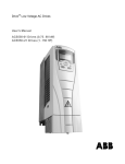
RBU
Operation Manual
z
Thank you very much for your buying RBU series regenerative break unit.
z
Before use, please read this manual thoroughly to ensure proper usage. Keep this
manual at an easily accessible place so that can refer anytime as necessary.
Safety Precautions
Please read this operation manual carefully before installation, operation, maintenance or
inspection.
In this manual, the safety precautions were sorted to “WARNING” or “CAUTION”.
WARNING
CAUTION
Indicates a potentially dangerous situation which, if can not
avoid will result in death or serious injury.
Indicates a potentially dangerous situation which, if can not
avoid will cause minor or moderate injury and damage the
device. This
Symbol is also used for warning any un-safety operation.
In some cases, even the contents of “CAUTION” still can cause serious accident.
Please follow these important precautions in any situation.
★ NOTE indicate the necessary operation to ensure the device run properly.
I
TABLE OF CONTENTS
TABLE OF CONTENTS ............................................................................................ II
LIST OF FIGURES ................................................................................................... III
1. INTRODUCTION................................................................................................. 1
1.1 Technology Features .................................................................................... 1
1.2 Description of Name Plate ........................................................................... 2
1.3 Selection Guide ............................................................................................ 2
1.4 External Dimension ...................................................................................... 3
2. INSPECTION ...................................................................................................... 4
3. INSTALLATION................................................................................................... 5
3.1 Environmental Requirement......................................................................... 6
3.2 Installation Space ......................................................................................... 7
3.3 Dimensions of External Keypad ................................................................... 7
3.4 Disassembly ................................................................................................. 8
4. WIRING ............................................................................................................... 9
4.1 Terminal Configuration ............................................................................... 10
4.1.1 Main Circuit Terminals ..................................................................... 10
4.1.2 Control Circuit Terminals ................................................................. 10
4.2 Wiring Daragram ........................................................................................ 12
5.
OPERATION.................................................................................................... 13
5.1 Keypad Description .................................................................................... 13
5.1.1 Keypad schematic diagram ............................................................. 13
5.1.2 Key function description .................................................................. 13
5.1.3 Indicator light description................................................................. 14
5.2 Function parameters .................................................................................. 14
5.3 Detailed function description ...................................................................... 17
6. TROUBLE SHOOTING ....................................................................................... 19
7.
MAINTENANCE .............................................................................................. 21
7.1 Daily Maintenance...................................................................................... 21
7.2 Periodic Maintenance................................................................................. 21
8.3 Replacement of wearing parts ................................................................... 22
II
LIST OF FIGURES
Figure 1.1
Nameplate of RBU......................................................................................... 2
Figure1.2
External dimensions. ...................................................................................... 3
Figure 3.1
Relationship between output current and altitude. ........................................ 6
Figure 3.2
Safety space.................................................................................................. 7
Figure 3.3
Dimension of big keypad. .............................................................................. 7
Figure 3.4
Disassembly of cover. ................................................................................... 8
Figure 4.1
Main circuit terminals................................................................................... 10
Figure 4.2
Control circuit terminals. .............................................................................. 10
Figure 4.3
Wiring Diagram............................................................................................ 12
Figure 5.1
Keypad schematic diagram. ........................................................................ 13
III
Introduction
1.
INTRODUCTION
1.1 Technology Features
Voltage Range
380V
Break Moment
60s with 100% of rated torque (25% Duty cycle), can
continuously run with 80% of rated torque.
AC Power
380VAC, 50/60Hz
AC Voltage Range
+10% to -15%, the imbalance between phases less than
2%.
AC Frequency Range
Less than 3Hz
Control Mode
Current Control with 120°
AC Power Factor
Higher than 0.9
Overload Capacity
30s with 150% of rated current
Operation Mode
External terminal, Keyboard
Fault Output
Relay output
Status Display
LED Keyboard
Analog Output
Voltage (0-10V)
Over current Protection
220% rated current
Over load protection
30s with 150% of rated current
Over voltage
DC: 800V
Overtemperature
Temperature resistance detection
AC phase failure fault
AC phase failure
AC frequency failure
Fluctuating higher than 3Hz
fault
Power light display
DC: higher than 50V
1
Introduction
1.2 Description of Name Plate
Figure 1.1
Nameplate of RBU.
1.3 Selection Guide
Model No.
Input
voltage
Rated
Power
(KW)
DC rated
current (A)
DC rated
current (A)
RBU-7R5-4
380V
7.5
13
10
RBU-011-4
380V
11
19
15
RBU-015-4
380V
15
26
20
RBU-018-4
380V
18.5
32
25
RBU-022-4
380V
22
37
30
RBU-030-4
380V
30
51
40
RBU-037-4
380V
37
64
50
RBU-045-4
380V
45
77
60
RBU-055-4
380V
55
96
75
RBU-075-4
380V
75
128
100
2
Size
Introduction
1.4 External Dimension
Figure1.2
Power
(kW)
A
(mm)
B
(mm)
Installation
Dimension
7.5-22
30-75
External dimensions.
L
(mm)
W
(mm)
D
(mm)
External Dimension
Installation
Hole
(mm)
In developing
140
130
577
3
220
236
6
Inspection
2.
INSPECTION
CAUTION
● Don’t install or use any RBU that is damaged or have fault part, otherwise may
cause injury.
Check the following items when unpacking the RBU,
1. Inspect the entire exterior of the RBU to ensure there are no scratches or other
damage caused by the transportation.
2. Ensure there is operation manual and warranty card in the packing box.
3. Inspect the nameplate and ensure it is what you ordered.
4. Ensure the optional parts are what you need if have ordered any optional parts.
Please contact the local agent if there is any damage in the RBU or optional parts.
4
Installation
3.
INSTALLATION
WARNING
●
The person without passing the training manipulate the device or any rule in the
“Warning” being violated, will cause severe injury or property loss. Only the person,
who has passed the training on the design, installation, commissioning and
operation of the device and gotten the certification, is permitted to operate this
equipment.
● Input power cable must be connected tightly, and the equipment must be grounded
securely.
● Even if RBU is not running, the following terminals still have dangerous voltage:
- Power Terminals: R, S, T
- Motor Connection Terminals: U, V, W.
● When power off, should not install the RBU until 5 minutes after, which will ensure the
device discharge completely.
● The section area of grounding conductor must be no less than that of power supply
cable.
CAUTION
●When
moving the RBU please lift by its base and don’t lift by the panel. Otherwise
may cause the main unit fall off which may result in personal injury.
● Install the RBU on the fireproofing material (such as metal) to prevent fire.
● When need install two or more RBU in one cabinet, cooling fan should be provided to
make sure that the air temperature is lower than 45°C. Otherwise it could cause fire
or damage the device.
5
Installation
3.1 Environmental Requirement
3.1.1
Temperature
Environment temperature range: -10°C ~ +40°C. RBU will be derated if ambient
temperature exceeds 40°C.
3.1.2
Humidity
Less than 95% RH, without dewfall.
3.1.3
Altitude
RBU can output the rated power when installed with altitude of lower than 1000m. It will
be derated when the altitude is higher than 1000m. For details, please refer to the
following figure:
(m)
Figure 3.1
3.1.4
Relationship between output current and altitude.
Impact and Oscillation
It is not allowed that the RBU falls down or suffers from fierce impact or the RBU installed
at the place that oscillation frequently.
3.1.5
Electromagnetic Radiation
Keep away from the electromagnetic radiation source.
3.1.6
Water
Do not install the RBU at the wringing or dewfall place.
3.1.7
Air Pollution
Keep away from air pollution such as dusty, corrosive gas.
3.1.8
Storage
Do not store the RBU in the environment with direct sunlight, vapor, oil fog and vibration.
6
Installation
3.2 Installation Space
Figure 3.2
Safety space.
Notice: Add the air deflector when apply the up-down installation.
3.3 Dimensions of External Keypad
Figure 3.3
Dimension of big keypad.
7
Installation
3.4 Disassembly
Figure 3.4
Disassembly of cover.
8
Wiring
4.
WIRING
WARNING
● Wiring must be performed by the person certified in electrical work.
● Forbid testing the insulation of cable that connects the RBU with high-voltage
insulation testing devices.
● Cannot install the RBU until discharged completely after the power supply is switched
off for 5 minutes.
● Be sure to ground the ground terminal.
400V class: Ground resistance should be 10Ω or less,
Otherwise, it might cause electric shock or fire.
● Connect input terminals (R, S, T) and output terminals (U, V, W) correctly.
Otherwise it will cause damage the inside part of RBU.
● Do not wire and operate the RBU with wet hands.
Otherwise there is a risk of electric shock.
CAUTION
●Check
to be sure that the voltage of the main AC power supply satisfies the rated
voltage of the RBU.
Injury or fire can occur if the voltage is not correct.
● Connect power supply cables and regenerative cables tightly.
9
Wiring
4.1 Terminal Configuration
4.1.1 Main Circuit Terminals
Figure 4.1
Main circuit terminals.
Main circuit terminal functions are summarized according to the terminal symbols in the
following table. Wire the terminal correctly for the desired purposes.
Terminal Symbol
R、S、T
Function Description
Terminals of 3 phase main power
(+)、(-)
Input terminals of power regenerative
Terminal of ground (PE)
4.1.2 Control Circuit Terminals
Figure 4.2
Control circuit terminals.
Control circuit terminals
Terminal
Description
ON-OFF signal input, optical coupling with +24V and COM. Short
connect with COM.
S1~S4
S1: When terminal control is valid, automatical input;
S2: When terminal control is un-valid, manual input;
S3: Multi-function terminal (Default is external fault input)
S4: Multi-function terminal (Default is fault reset input)
10
Wiring
Terminal
COM
Description
Common ground terminal for digital signal and +24V (or external
power supply).
Open collector output terminal, The corresponding common
Y
ground terminal is COM.
External voltage range: 0~24V
Output current range:
+24V
AO
GND
RO1A、
RO1B、RO1C
0~50mA
Provide output power supply of +24V.
Maximum output current: 150mA
Analog output terminal. Output range: 0~10V
Common ground terminal of analog signal and AO.
GND must isolated from COM.
RO1 relay output: RO1A—common; RO1B—NC; RO1C—NO.
Contact capacity: AC 250V/3A, DC 30V/1A.
11
Wiring
4.2 Wiring Daragram
U
AC Reactor
R
Electromagnetism contactor
T
(+)/P
M
V
INVERTER
S
W
(-)/N
PE
Suggest to use FU
(+)
R
S
(-)
RBU
T
Automatic running
S1
Manual running
S2
External fault
S3
Faulty reset
S4
CN9
AO
Interface for
external keyboard
~
Analog output
0-10V/0-20mA
GND
COM
Y
+24V
COM
Open collector
output
PE
ROA1
ROB1
ROC1
Figure 4.3
Wiring Diagram.
12
Relay
output 1
Operation
5.
OPERATION
5.1 Keypad Description
5.1.1 Keypad schematic diagram
Figure 5.1
Keypad schematic diagram.
5.1.2 Key function description
Key
Name
Programming
Key
Enter Key
Function Description
Entry or escape of first-level menu.
Progressively enter menu and confirm parameters.
UP Increment
Key
Progressively increase data or function codes.
DOWN
Decrement Key
Progressive decrease data or function codes.
Shift Key
In parameter setting mode, press this button to
select the bit to be modified. In other modes,
cyclically displays parameters by right shift
13
Operation
Run Key
Start to run the inverter in keypad control mode.
STOP/RESET
Key
In running status, restricted by P7.04, can be used to
stop the inverter.
When fault alarm, can be used to reset the inverter
without any restriction.
5.1.3 Indicator light description
1)
Function Indicator Light Description
Function indicator
RUN/TUNE
LOCAL/REMOT
Description
Extinguished: stop status
Light on: operating status
Extinguished: keypad control
Flickering: terminal control
Light on: communication control
Extinguished: normal operation status
Flickering: overload pre-warning status
TRIP
2) Unit Indicator Light Description
3)
Unit indicator
Description
Hz
Frequency unit
A
Current unit
V
Voltage unit
RPM
Rotating speed unit
%
Percentage
Digital Display
Have 5 digit LED , which can display all kinds of monitoring data and alarm codes such as
mains voltage, bus voltage, output current and so on.
5.2 Function parameters
Function
Code
Name
Factory
Setting
Modify
Serial
No.
0~1
0: Keyboard control
1: Terminal control
S1 valid: automatical mode
S2 valid: manual mode
1

0
0~1
0: Automatical mode
1: Manual mode
0

1
Description
P0 Group: Basic Function
P0.00
Control mode
P0.01
Keyboard control
mode
14
Operation
Function
Code
Name
Description
Factory
Setting
Modify
Serial
No.
P0.02
ON/OFF filter times
1~10
1

2
P0.03
Current protection
threshold of trip-free
0.5~30.0%
5.0%
O
3
P0.04
Regenerative voltage
of start
400.0~760.0V
650.0V
O
4
P0.05
Regenerative voltage
range
0.0~60.0V
12.0V
O
5
P0.06
Regenerative stop
time
0.1~10.0S
1.0S
O
6
P0.07
Input frequency
0

7
P0.08
S3 terminal function
1~15
3: Valid when short connect S3 and
COM
Others, reserved
3 (External
fault))

8
P0.09
S4 terminal function
1~15
2: Valid when short connect S4 and
2 (Fault reset))
COM
Others, reserved

9
P0.10
Reserved
1
O
10
P0.11
AO function selection
1
O
11
P0.12
AO lower limit
0.0%~100.0%
0.0%
O
12
0.00V ~10.00V
0.00V
O
13
0.0%~100.0%
100.0%
O
14
0.00V ~10.00V
10.00V
O
15
1
O
16
0
O
17
P0.13
P0.14
P0.15
0~1
0: 50HZ
1: 60HZ
0~8
0: DC bus line voltage (0~1000V)
1: Output current (0~200.0%)
2~8: Reserved
AO lower limit
corresponding output
AO upper limit
AO upper limit
corresponding output
0~1
P0.16
Cooling fan running 0: Run after start
mode
1: Start when temperature higher
than 45℃
P0.17
Y ON/OFF output
selection
0~15
0: no output
15
Operation
Function
Code
Factory
Setting
Modify
Serial
No.
4 (Fault output)
O
18
300.0V ~400.0V
380.0V
O
19
Name
Description
1: Running command is valid
P0.18
Relay output
selection
2: Regenerative running
3: Reserved
4: Fault output
5~15: Reserved
P0.19
Under voltage
protection
P0.20
Fault reset times
0~3
0

20
P0.21
Fault reset time
0.1~10.0S
3.0S

21
P0.22
input phase-failure
1

22
1.0S

23
●
24

25
●
26
●
27
●
28
●
29
AC
protection
0~1
0: Unvalid
1: Valid
AC
P0.23
input phase-failure
0.5~10.0S
protection time
P0.24
Running time
Restore function
P0.25
parameters,
clear fault record
P0.26
Software version
P0.27
Fourth latest fault
type
P0.28
Third latest
fault type
P0.29
Second latest
fault type
0~XXXXXH
0~2
0: no change
1: Restore factory setting
0
2: Clear fault record
0~26
0: No fault
1: Reserved
2: Reserved
3: IGBT protection(OUT3)
4: Reserved
16
Operation
Function
Code
P0.30
P0.31
P0.32
Modify
Serial
No.
●
30
●
31
●
32
0
O
33
0~65535
*****

34
Description
Factory
Setting
Modify
Serial
No.
0~1
0: Keyboard control
1: Terminal control
S1 valid: automatical mode
S2 valid: manual mode
1

0
0~1
0: Automatical mode
1: Manual mode
0

1
Name
Latest
fault type
Description
Factory
Setting
5: Reserved
6: Over-current (OC3)
7: Reserved
8: Reserved
9: Over-voltage (OV3)
10: DC bus Under-voltage(UV)
11: Reserved
12: Inverter overload (OL2)
13: Reserved
14: Input phase failure (SPI)
15: Reserved
16: IGBT overheat (OH2)
17: External fault (EF)
18: Reserved
19: Current detection fault (ITE)
20: Reserved
21: EEPROM fault (EEP)
22: Reserved
23: Reserved
24: Reserved
25: Control power fault (CP)
26: Parameter setting wrong (PEr)
Output current at
current fault
DC bus voltage at
current fault
0~1
P0.33
Parameter locked
0: No locked
1: Locked
P0.34
Factory password
5.3 Detailed function description
Function
Code
Name
P0.00
Control mode
P0.01
Keyboard control
mode
17
Operation
Automatical mode:
When in automatical mode, RBU detects the bus line voltage and realizes start and stop
automatically.
When the bus voltage is higher than P0.04, start the regeneration.
When the bus voltage is lower than P0.04, stop the regeneration.
Manual mode:
When start the running command, RBU regenerates all the time.
18
Trouble Shooting
6. TROUBLE SHOOTING
Fault
Code
Fault Type
Reason
Solution
1. IGBT module fault.
2. Malfunction caused by
interference.
3. Grounding is not properly.
1. Inspect external
equipment and eliminate
interference. Press
STOP/RST to reset
2. Ask for support.
Over-current
when running
1.Sundden change of
regenerative power
2.Lower power of RBU
1. Decrease the sudden
change of regenerative
power
2. Use RBU with higher
power
3. Ask for support
Over-voltage
when running
1. Sundden change of
regenerative power
2. More higher threshold
setting of RBU
3. No enough capacity of RBU
1. Set
2. Decrease
regenerative voltage
threshold
3. Use RBU with higher
power
4. Ask for support
OL
RBU overload
1. More lower threshold
setting of RBU
2. Sundden change of
regenerative power
3. More lower power of RBU
SPI
Input phase
failure
Power off at AC input
EF
External fault
S3: External fault input
terminal take effect.
1. Select variable
frequency motor.
2. Check and adjust V/F
curve.
3. Check and adjust
PB.03
4. Check the load.
1. Check AC input
power supply.
2. Ask for support
Inspect external
equipment.
1. Cooling fans of inverter
stop or damaged.
2. Obstruction of ventilation
channel
3. Ambient temperature is too
high.
1. Install cooling unit.
2. Remove heat source.
3. Replace cooling fan
4. Clear the ventilation
channel.
5. Ask for support
OUT
OC
OV
OH
IGBT fault
IGBT overheat
19
Trouble Shooting
CE
Communication
fault
ITE
Current
detection fault
EEP
EEPROM fault
CP
PER
Control power
fault
Parameters
setting wrong
1. Improper baud rate setting.
2. Receive wrong data.
3. Communication is
interrupted for Long time
Wires or connectors of control
board are loose
Read/Write fault of control
parameters
Auxiliary power damaged
20
1. Set proper baud rate.
2. Check communication
devices and signals.
1. Check the wiring.
2. Ask for support.
Press STOP/RESET to
reset
Ask for support
Ask for support
Maintenance
7.
MAINTENANCE
WARNING
● Maintenance must be performed according to designated maintenance
methods.
● Maintenance, inspection and replacement of parts must be performed only by
certified person.
● After turning off the main circuit power supply, wait for 10 minutes before
maintenance or inspection.
● DO NOT directly touch components or devices of PCB board. Otherwise
inverter can be damaged by electrostatic.
● After maintenance, all screws must be tightened.
7.1 Daily Maintenance
In order to prevent the fault of RBU to make it operate smoothly in high-performance for a
long time, user must inspect the RBU periodically (within half year). The following table
indicates the inspection content.
Check Item
Content
Temperature/Humidity
Ensure the environmental temperature is between
0℃~50℃, and humidity is between 20~90%.
Oil mist and dust
Ensure there are no oil mist and dust in the RBU.
RBU
Inspect RBU to ensure whether there are abnormity
heat and vibration.
Fan
Ensure the fan is running well, nothing inside to block it.
Input Power
Ensure the input power voltage and frequency is in
allowed range.
7.2 Periodic Maintenance
In order to prevent the fault of RBU to make it operate smoothly in high-performance
for a long time, user must inspect the RBU periodically (within half year). The following
table indicates the inspection content.
21
Maintenance
Inspection Item
Inspection Content
Solution
Screw of external
terminal
Screws are loose or not?
Tighten up
PCB Board
Dust, Dirty object
Clean them completely by dry
compressed air
Fan
Electrolytic
Capacitor
Abnormity noise and vibration,
cumulative time is over 20,000
hours or not?
Color changed or not, any
peculiar smell?
Heat emission
Dust, dirty object
Power Components
Dust, dirty object
1. Clean them
2. Replace the fan
Replace electrolytic capacitor
Clean them completely by dry
compressed air
Clean them completely by dry
compressed air
8.3 Replacement of wearing parts
Fans and electrolytic capacitors are wearing part, please make periodic replacement to
ensure long term, safety and failure-free operation. The replacement periods are as
follows:
◆Fan: Must be replaced when using up to 20,000 hours;
◆Electrolytic Capacitor: Must be replaced when using up to 30,000~40, 000 hours.
22