1
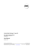
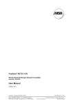
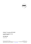
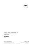
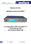
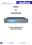
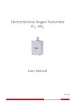
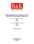
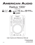
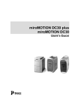
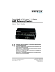
µ-Gard MA01-1110 Electrochemical Carbon Monoxide Transmitter Serial No. MA0X-00X User Manual June, 2014 µGard is a registered trademark of MSR Phone 0049(0)8531/9004-0 Fax: 0049(0)8531/9004-54 MSR-Electronic GmbH, Würdinger Str. 27, D 94060 Pocking GAMA1110_E_0614 www:msr-electronic.de Specification subject to change without notice Printed in Germany User Manual - µ-Gard® CO Transmitter MA01-1110 Page 2 1 Intended Use ........................................................................................................................................3 2 Functional Description .......................................................................................................................3 3 Installation............................................................................................................................................4 3.1 3.2 4 Electrical Connection ..........................................................................................................................5 4.1 4.2 5 Calibration Zero Point (Output Signal 4 mA) ...............................................................................6 Calibration Span ..........................................................................................................................6 Calculation of Control Span Voltage ............................................................................................7 Inspection and Service .......................................................................................................................8 6.1 6.2 6.3 7 Wiring Connection .......................................................................................................................5 Output Signal ...............................................................................................................................5 Commissioning ...................................................................................................................................6 5.1 5.2 5.3 6 Mounting Instructions ..................................................................................................................4 Installation....................................................................................................................................4 Inspection ....................................................................................................................................8 Service and Calibration................................................................................................................8 Exchange of Sensor Element ......................................................................................................8 Troubleshooting ..................................................................................................................................9 7.1 Diagnostics at the Transmitter .....................................................................................................9 8 Cross-sensitivity Data .........................................................................................................................9 9 Specifications ....................................................................................................................................10 10 Calibration Adapter ...........................................................................................................................11 11 Spare Parts List .................................................................................................................................11 12 Part Disposal......................................................................................................................................11 13 Notes and General Information ........................................................................................................12 13.1 13.2 13.3 13.4 Intended Product Application .................................................................................................12 Installers` Responsibilities .....................................................................................................12 Maintenance ..........................................................................................................................12 Limited Warranty....................................................................................................................12 14 CE - Declaration of Conformity ........................................................................................................13 15 Appendix Enclosure A and 5 ............................................................................................................14 15.1 15.2 15.3 15.4 15.5 15.6 15.7 15.8 Enclosure Type A ...................................................................................................................14 Enclosure Type 5 ...................................................................................................................14 Installation ..............................................................................................................................15 Wiring Connection .................................................................................................................15 Calibration ..............................................................................................................................15 Specifications .........................................................................................................................15 Exchange of Sensor Element ................................................................................................16 Opening of the Enclosure Type 5 ..........................................................................................16 µGard is a registered trademark of MSR Phone 0049(0)8531/9004-0 Fax: 0049(0)8531/9004-54 MSR-Electronic GmbH, Würdinger Str. 27, D 94060 Pocking GAMA1110_E_0614 www:msr-electronic.de Specification subject to change without notice Printed in Germany User Manual - µ-Gard® CO Transmitter MA01-1110 Page 3 Electrochemical Carbon Monoxide Transmitter 1 Intended Use The µGard CO analog gas transmitter MA01-1110 with 4 – 20 mA / 2 - 10 V output is used for the continuous monitoring of the ambient air to detect the presence of carbon monoxide (CO) gas concentrations within the ambient conditions defined in the Specifications. Main application ranges are underground car parks, tunnels, engine test stations, shelters, loading areas etc. The intended sites are all areas being directly connected to the public low voltage supply, e.g. residential, commercial and industrial ranges as well as small enterprises (according to EN50 082). The µGard® CO analog transmitter must not be used in potentially explosive atmospheres. The transmitter must only be employed in areas within the environmental conditions as specified in the Technical Data. 2 Functional Description The sensor portion of the transmitter is a micro-fuel cell, which is completely sealed. The ambient air to be monitored diffuses through a membrane filter into the liquid electrolyte of the sensor. The chemical process of the measurement is one of oxidation where one molecule of the target gas is exchanged for one molecule of oxygen. The reaction drives the oxygen molecule to the counter electrode, generating a current signal (nA) between the two electrodes. This signal is linear to the volume concentration of the sensed gas. The signal is evaluated by the connected amplifier and transformed into a linear 4 - 20 mA / 2 – 10 V output signal. Electrochemical processes always lead by-and-by to a loss of sensitivity. Therefore regular calibration of zeropoint and gain with the potentiometers Zero and Gain is necessary. There is a small quantity of corrosive liquid in the sensor element. If in case of damage persons or objects touch the liquid, you have to clean the affected areas as fast and carefully as possible with tap water. Out of use sensors must be disposed in the same way as batteries. Silicon leads to an undesirable chemical reaction in the sensor and so causes a drift of the zero-point to the positive side. Prolonged exposure leads to an important reduction of the sensor sensibility. After exposure to silicone the sensor has to be replaced in order to provide for the functional reliability furthermore. Electronics can be destroyed by static electricity. Therefore, do not touch the equipment without a wrist strap connected to ground or without standing on a conductive floor (acc. to EN 61340-5-1). µGard is a registered trademark of MSR Phone 0049(0)8531/9004-0 Fax: 0049(0)8531/9004-54 MSR-Electronic GmbH, Würdinger Str. 27, D 94060 Pocking GAMA1110_E_0614 www.msr-electronic.de Specification subject to change without notice Printed in Germany User Manual - µ-Gard® CO Transmitter MA01-1110 Page 4 3 Installation 3.1 Mounting Instructions When choosing the mounting site please pay attention to the following: The specific weight of carbon monoxide CO is smaller than that of air (factor 0.967). Recommended mounting height is 1.5 m (5 feet) to 1.8 m (6 feet) above floor. Choose mounting location of the sensor according to local regulations. Consider the ventilation conditions! Do not mount the transmitter in the centre of the airflow (air passages, suction holes). Mount the transmitter at a location with minimum vibration and minimum variation in temperature (avoid direct sunlight). Avoid locations where water, oil etc. may influence proper operation and where mechanical damage might be possible. Provide adequate space around the sensor for maintenance and calibration work. 3.2 Installation Open cover of enclosure. Fix the enclosure by the 2 screws (gas inlet to the ground). Replace the cover. Mounting 50 50mm Zero Gain Mounting Zer o Te st Gain Test Gas inlet “DOWN” Gas inlet “DOWN” Mounting height: See table Cross Senitivity 79 Gas inlet! Prior to commissioning, cut protective cap carefully off with a knife. Fig.1 Mounting µGard is a registered trademark of MSR Phone 0049(0)8531/9004-0 Fax: 0049(0)8531/9004-54 MSR-Electronic GmbH, Würdinger Str. 27, D 94060 Pocking GAMA1110_E_0614 www.msr-electronic.de Specification subject to change without notice Printed in Germany User Manual - µ-Gard® CO Transmitter MA01-1110 Page 5 4 Electrical Connection Installation of the electrical wiring should only be performed by a trained specialist according to the connection diagram, without any power applied to conductors and according to the corresponding regulations! Avoid any influence of external interference by using a shielded cable, but do not connect the shield. Recommended cable: J-Y(St)Y 2x2x0.8LG (18 AWG), maximum loop resistance 73 /1000 m 20.8 /1000 ft) When the PCB is mounted, it is important to ensure that the wire shields or any bare wires do not short the PCB. 4.1 Wiring Connection Insert cable and strip it off. Remove triple-pole socket board and connect the cable according to the wiring diagram. Replug the socket board correctly at the multi-pin connector. Close the cover. 1 2 3 24 VDC 2 - 10 V 0 VDC 24 VDC 4 - 20 mA 0 VDC 1 2 3 Controller Transmitter MA-11XX Fig.2 Wiring Diagram 0 VDC 2 - 10 V 24 VDC Open cover of enclosure. 4 - 20 mA 24 VDC Controller Transmitter MA-11XX Operation mode 4 - 20 mA Operation mode 2 - 10 V Gain Zero 1 2 3 Gain Zero Gain Zero Test Zero Gain Test Zero Gain 3 2 1 3 2 1 Fig.3 Electric Connection# R 40 Operation mode 4- 20 mA: The transmitter is always current source. Only 2-wire connection. Gain Zero 4.2 Output Signal Test 1 2 3 Operation mode 2 – 10 V: Remove R40 by using a wire cutter. Always 3-wire connection. Fig.4 Board µGard is a registered trademark of MSR Phone 0049(0)8531/9004-0 Fax: 0049(0)8531/9004-54 MSR-Electronic GmbH, Würdinger Str. 27, D 94060 Pocking GAMA1110_E_0614 www.msr-electronic.de Specification subject to change without notice Printed in Germany User Manual - µ-Gard® CO Transmitter MA01-1110 Page 6 5 Commissioning CO calibration gas is toxic, never inhale the gas! Symptoms: Dizziness, headache and nausea. Procedure if exposed: Bring into fresh air at once, consult a doctor. Please observe proper handling procedures for test gas bottles and the regulations according to TRGS 220! Prior to calibration the sensor element must be powered and fully stabilized for at least 1 hour without interruption. Calibration must only be performed under operation typical ambient conditions. Always consider the commissioning instructions when exchanging the sensor element. Only trained technicians should perform the following: Cut the protective cap at the gas inlet carefully off by using a knife (only for enclosure D / F). See fig.1. Select output signal (4 – 20 mA or 2 – 10 V). See 4.2. Check mounting location. Check power voltage. Calibrate the transmitter (if not factory calibrated). Required instruments to calibrate the transmitter: Test gas bottle with synthetic air or CO-free ambient air. Test gas bottle with CO. Concentration 30 – 70 % of the measuring range. The rest is synthetic air. Gas pressure regulator with flow meter. Calibration adapter with tubing. Type: XXXXX See Fig. 6. Digital voltmeter with range 0 – 10 VDC, accuracy 1%. Small screwdriver. 5.1 Calibration Zero Point (Output Signal 4 mA) Open cover of enclosure. Connect digital voltmeter to pin “Test” for zero-point calibration. Connect the calibration adapter to the sensor element. Apply zero calibration gas, 150 ml/min; 1 Bar (14.5 psi), or other CO-free air source. Wait one minute until the signal is stable, adjust signal with potentiometer ”Zero” until the signal is 40 mV ± 1 mV and stable (= 4 mA / 2V). 5.2 Calibration Span Connect calibration adapter to the sensor element. Connect digital voltmeter to pin “Test”. Apply span calibration gas (30 – 70 % CO of measuring range), 150 ml/min; 1 Bar (14.5 psi). Wait two minutes until the signal is stable, adjust signal with potentiometer ”Gain” until the signal corresponds to the calculated value, see calculation for control voltage 5.3, ± 1 mV and is stable. At a loss of sensitivity of more than 70% caused by ageing, operational or climatic influences, calibration will not be possible any more. Then the sensor has to be replaced. µGard is a registered trademark of MSR Phone 0049(0)8531/9004-0 Fax: 0049(0)8531/9004-54 MSR-Electronic GmbH, Würdinger Str. 27, D 94060 Pocking GAMA1110_E_0614 www.msr-electronic.de Specification subject to change without notice Printed in Germany User Manual - µ-Gard® CO Transmitter MA01-1110 Page 7 5.3 Calculation of Control Span Voltage The control voltage at the pin “Test” simulates the 4 – 20 mA signal at a 10 Ohm measuring resistance. Control span voltage (mV) = 160 (mV) x test gas concentration CO (ppm) + 40 (mV) measuring range CO (ppm) Example: Measuring range CO Test gas concentration Control voltage 300 ppm 200 ppm CO 146,7 mV 160 (mV) x 200 (ppm) + 40 (mV) = 146,7 mV 300 (ppm) mV Control voltage: Zero calibration: Gain calibration: = (mV) 40 mV ±2 mV 160 mV x CO (ppm) + 40 mV Measuring range (ppm) Flow rate: 150 ml/min ± 20 ml Zero Gain Pressure: 1 Bar ±10% Test Test gas: Zero calibration: Gain calibration: Synthetic air CO (ppm) with 30 – 70 % concentration of the measuring range, rest is synthetic air. Fig.5 Calibration µGard is a registered trademark of MSR Phone 0049(0)8531/9004-0 Fax: 0049(0)8531/9004-54 MSR-Electronic GmbH, Würdinger Str. 27, D 94060 Pocking GAMA1110_E_0614 www.msr-electronic.de Specification subject to change without notice Printed in Germany User Manual - µ-Gard® CO Transmitter MA01-1110 Page 8 6 Inspection and Service Inspection, service and calibration of the transmitters should be done by trained technicians and executed at regular intervals. We therefore recommend concluding a service contract with MSR or one of their authorized partners. According to EN 45544-4, inspection and service has to be executed at regular intervals. The maximum intervals have to be determined by the person responsible for the gas warning system according to the legal requirements. MSR-E recommends checking the µ- Gard Transmitter MA011110 every three months and maintaining it every 12 months. If different intervals are indicated, always consider the shortest interval. Inspections and services must be documented. The date for the next maintenance has to be affixed to the transmitter. 6.1 Inspection The µ- Gard Transmitter should be controlled regularly by a competent person according to EN 45544-4. The following has to be checked in particular: Maintenance/ calibration interval not exceeded. Visual inspection of the transmitter including cable for damage etc. Remove dust deposits, especially at the gas inlet. For enclosure type A: The filter at the gas inlet has to be replaced if extremely dirty. 6.2 Service and Calibration When performing the maintenance you have to do the calibration and the functional test in addition to the inspection. Calibration: See section 5. Functional test: Check the output signal at the test pins during calibration. 6.3 Exchange of Sensor Element Sensor should always be exchanged without power applied (remove the socket board): Unscrew the two fixing bolts. Remove the board with the sensor upwards out of the sensor cup. Unplug old sensor element from the PCB, plug in new original sensor element. Plug in the PCB with the sensor into sensor cup and tighten it by the screws. Plug in the socket board correctly. See fig.3. Calibrate the sensor (see section 5.). µGard is a registered trademark of MSR Phone 0049(0)8531/9004-0 Fax: 0049(0)8531/9004-54 MSR-Electronic GmbH, Würdinger Str. 27, D 94060 Pocking GAMA1110_E_0614 www.msr-electronic.de Specification subject to change without notice Printed in Germany User Manual - µ-Gard® CO Transmitter MA01-1110 Page 9 7 Troubleshooting 7.1 Diagnostics at the Transmitter Trouble Cause Solution Output signal 0 mA and control voltage 0 V Power voltage not applied or Measure power voltage at terminal block not connected correctly. 1 (+) and 2 (-) (16 – 28 VDC) Socket board not plugged in Plug in the socket board acc. to fig.3. correctly Output signal < 3 mA and/or Transmitter not calibrated control voltage < 30 mV Calibrate transmitter Control voltage doesn’t reach the calculated value Replace sensor element Sensor sensitivity < 30 % If faults cannot be eliminated by the above mentioned actions or if other faults not described in this table occur, please contact the service. 8 Cross-sensitivity Data The table does not claim to be complete. Other gases can have an influence on the sensitivity, too. The indicated sensitivity data are only standard values referring to new sensor elements. Gas Acetone Chemical formula Gas concentration Exposure Time Influence on the reading (min) (ppm CO) C3H6O 1000 ppm 5 0 ppm Acetylene C2H2 40 ppm 5 80 ppm Ammonia NH3 100 ppm 5 0 ppm Carbon dioxide CO2 5000 ppm 5 0 ppm Chlorine CL2 2 ppm 5 0 ppm Ethanol C2H5OH 2000 ppm 30 5 ppm H2 100 ppm 5 20 ppm H2S 25 ppm 5 0 ppm C3H8O 200 ppm 120 0 ppm Nitric oxide NO 50 ppm 5 8 ppm Nitrogen dioxide NO2 50 ppm 900 - 1 ppm Sulphur dioxide SO2 50 ppm 600 < 0.5 ppm Hydrogen Hydrogen sulphide Iso Propanol µGard is a registered trademark of MSR Phone 0049(0)8531/9004-0 Fax: 0049(0)8531/9004-54 MSR-Electronic GmbH, Würdinger Str. 27, D 94060 Pocking GAMA1110_E_0614 www.msr-electronic.de Specification subject to change without notice Printed in Germany User Manual - µ-Gard® CO Transmitter MA01-1110 Page 10 9 Specifications Electrical Power supply: Power consumption: Sensor Performance Type of gas Sensor element 16 - 28 VDC (reverse polarity protected) 22 mA, (0.6 VA), max. Carbon monoxide (CO) Electrochemical, diffusion Measuring range 0 – 300 ppm factory set, 0 - 200 to 0 – 300 ppm adjustable Accuracy Repeatability Long term drift zero-point Response time Sensor life expectancy Mounting height Type of Control ± 3 ppm ± 3 % of reading 5 % signal loss/year t90 50 sec. > 5 years, normal operating environment 1.5 to 1.8 m (5 to 6 ft.) above floor Analog output signal Operating Environment Humidity Range: Continuous Intermittent Working temp.: Continuous Intermittent Pressure range Storage temperature Storage time Physical characteristics Enclosure Enclosure material Flammability Enclosure colour Dimensions (W x H x D) Weight Protection class Mounting Cable entry Wire connection Wire distance Approvals Guidelines Warranty 4 – 20 mA, load 500 2 -10 V, load ≥ 50 k Proportional, overload and short-circuit protected 15 to 90 % RH non-condensing 0 to 99 % RH non-condensing -10 °C to + 50 °C (14 °F to 122 °F) -20 °C to + 50 °C (-4 °F to 122 °F) Atmospheric ±10% 5 °C to + 30 °C (41 °F to 86 °F) Max. 6 months Type D Type F Polycarbonate GW Plast 75 GWT UL 94 V2 UL 94 V0 RAL 7032 (light grey) RAL 7032 (light grey) 94 x 65 x 57 mm Round: (d x H) 87 x 45.5 mm 0.3 kg 0.2 kg IP 43 IP 43 Wall mounting, pillar mounting 1 x M 20 Screw-type terminal: 0.25 to. 2.5 mm2 (24 to 14 AWG) Max. loop resist. 500 (= wire resistor + controller input resistor) VDI 2053, Air Treatment Systems for Garages and Tunnels (in preparation) Sensor: UL recognized EMC Directive 2004/108/EEC CE One year material (without sensor) µGard is a registered trademark of MSR Phone 0049(0)8531/9004-0 Fax: 0049(0)8531/9004-54 MSR-Electronic GmbH, Würdinger Str. 27, D 94060 Pocking GAMA1110_E_0614 www.msr-electronic.de Specification subject to change without notice Printed in Germany User Manual - µ-Gard® CO Transmitter MA01-1110 Page 11 10 Calibration Adapter Enclosure Type A and 5; Enclosure Type D and F Type: Calibr-set-AT 1110S02 Type: Calibr-set MA1110S2 Fig.6 Calibration Adapter 11 Spare Parts List Description Order No. Sensor Sense00-1110 PCB without sensor MA-1110-003 Connector triple-pole MA_25..600.2353.0 Enclosure type D GMA_D-001 Enclosure type F GMA_F-001 Enclosure type A GMA_A-001 Enclosure type 5 GMA_5-001 Filter set for enclosure type D F_MA-10 12 Part Disposal Since August 2005 there are EC-wide directives defined in the EC Directive 2002/96/EC and in national codes concerning the waste electrical and electronic equipment and also regarding this device. For private households there are special collecting and recycling possibilities. For this device isn’t registered for the use in private households, it mustn’t be disposed this way. You can send it back to your national sales organisation for disposal. If there are any questions concerning disposal please contact your national sales organisation. Outside the EC, you have to consider the corresponding directives. µGard is a registered trademark of MSR Phone 0049(0)8531/9004-0 Fax: 0049(0)8531/9004-54 MSR-Electronic GmbH, Würdinger Str. 27, D 94060 Pocking GAMA1110_E_0614 www.msr-electronic.de Specification subject to change without notice Printed in Germany User Manual - µ-Gard® CO Transmitter MA01-1110 Page 12 13 Notes and General Information It is important to read this user manual thoroughly and clearly in order to understand the information and instructions. The µGard® transmitters must be used within product specification capabilities. The appropriate operating and maintenance instructions and recommendations must be followed. Due to on-going product development, MSR reserves the right to change specifications without notice. The information contained herein is based upon data considered to be accurate. However, no guarantee is expressed or implied regarding the accuracy of this data. 13.1 Intended Product Application The µGard® CO transmitters are designed and manufactured for control applications and air quality compliance in commercial buildings and manufacturing plants. 13.2 Installers` Responsibilities It is the installer’s responsibility to ensure that all µGard® transmitters are installed in compliance with all national and local codes and OSHA requirements. Installation should be implemented only by technicians familiar with proper installation techniques and with codes, standards and proper safety procedures for control installations and the latest edition of the National Electrical Code (ANSI/NFPA70). It is also essential to follow strictly all instructions as provided in the user manual. 13.3 Maintenance It is recommended to check the µGard® transmitter regularly. Due to regular maintenance any performance deviations may easily be corrected. Re-calibration and part replacement in the field may be implemented by a qualified technician and with the appropriate tools. Alternatively, the easily removable plug-in transmitter card with the sensor may be returned for service to MSR-Electronic-GmbH. 13.4 Limited Warranty MSR-Electronic-GmbH warrants the µGard® transmitters for a period of one (1) year from the date of shipment against defects in material or workmanship. Should any evidence of defects in material or workmanship occur during the warranty period, MSR-Electronic-GmbH will repair or replace the product at their own discretion, without charge. This warranty does not apply to units that have been altered, had attempted repair, or been subject to abuse, accidental or otherwise. The warranty also does not apply to units in which the sensor element has been overexposed or gas poisoned. The above warranty is in lieu of all other express warranties, obligations or liabilities. This warranty applies only to the µGard® transmitter. MSR-Electronic-GmbH shall not be liable for any incidental or consequential damages arising out of or related to the use of the µGard® transmitters. µGard is a registered trademark of MSR Phone 0049(0)8531/9004-0 Fax: 0049(0)8531/9004-54 MSR-Electronic GmbH, Würdinger Str. 27, D 94060 Pocking GAMA1110_E_0614 www.msr-electronic.de Specification subject to change without notice Printed in Germany User Manual - µ-Gard® CO Transmitter MA01-1110 Page 13 14 CE - Declaration of Conformity Declaration of Conformity Dokument-Nr. / Document No. CE_MAX1-1110_0610 Hersteller/ Manufacturer: Adresse/ Address: MSR - Electronic - GmbH Würdinger Str. 27 D-94060 Pocking Produktbezeichnung: Product Name: µ- Gard Gas Transmitter MAX1-1110 Series Die bezeichneten Produkte stimmen mit den Vorschriften folgender Europäischer Richtlinien überein: The mentioned products are conform to the instructions of the following European Regulations: Nummer/ Number: 2004 / 108 / EWG RICHTLINIE DES EUROPÄISCHEN RATES COUNCIL DIRECTIVE vom 31 Dezember 2004 / of 31st December 2004 zur Angleichung der Rechtsvorschriften der Mitgliedstaaten über die elektromagnetische Verträglichkeit. on the approximation of the laws of the Member States relating to electromagnetic compatibility Nummer/ Number: EN 50270:2006 RICHTLINIE DES EUROPÄISCHEN RATES COUNCIL DIRECTIVE vom Mai 2007 / of May 2007 Elektromagnetische Verträglichkeit von elektrischen Geräten zur Detektion und Messung von brennbaren und toxischen Gasen oder Sauerstoff. Electromagnetic compatibility – Electrical apparatus for the detection and measurement of combustible gases, toxic gases or oxygen. Aussteller/ Issued by: Datum / Date: MSR - Electronic - GmbH Pocking, 21.06.10 Rechtsverbindliche Unterschrift/ binding signature: ............................................... Diese Erklärung bescheinigt die Übereinstimmung mit den genannten Richtlinien, beinhaltet jedoch keine Zusicherung von Eigenschaften. Die Sicherheitshinweise der mitgelieferten Produktdokumentation sind zu beachten. This declaration certifies the conformity to the mentioned directives. It does not confirm any attributes. The security hints of the specific instruction manuals have to be followed µGard is a registered trademark of MSR Phone 0049(0)8531/9004-0 Fax: 0049(0)8531/9004-54 MSR-Electronic GmbH, Würdinger Str. 27, D 94060 Pocking GAMA1110_E_0614 www.msr-electronic.de Specification subject to change without notice Printed in Germany User Manual - µ-Gard® CO Transmitter MA01-1110 Page 14 15 Appendix Enclosure A and 5 15.1 Enclosure Type A 115 mm Mounting 1 2 3 1500 - 1800 mm Zero Gain Test Mounting Fig.7 Enclosure type A 79 mm 15.2 Enclosure Type 5 d = 5 mm Mounting d = 5 mm 1500 - 1800 mm Zero Gain Mounting 84 mm 1 2 3 Test Fig.8 Enclosure type 5 µGard is a registered trademark of MSR Phone 0049(0)8531/9004-0 Fax: 0049(0)8531/9004-54 MSR-Electronic GmbH, Würdinger Str. 27, D 94060 Pocking GAMA1110_E_0614 www.msr-electronic.de Specification subject to change without notice Printed in Germany User Manual - µ-Gard® CO Transmitter MA01-1110 Page 15 15.3 Installation Open cover. Fix the enclosure by 2 screws (gas inlet always downwards). Close cover. 15.4 Wiring Connection Pay attention to the general information (section 4). Open cover. Insert cable, strip it off and connect it. Close cover. 15.5 Calibration Description, see point 5. mV Flow rate: 150 ml/min ± 20 ml 1 2 3 Pressure: 1 Bar ±10% Zero Gain Test Fig.9 Calibration for enclosure types A and 5 15.6 Specifications Physical characteristics Enclosure Enclosure material Flammability Enclosure colour Dimensions (W x H x D) Weight Protection class Mounting Cable entry Type A Polycarbonate UL 94 V2 RAL 7032 (light grey) 94 x 130 x 57 mm 0.3 kg IP 65 Wall mounting, pillar mounting Standard 1 x M 20 Type 5 V2A, 1mm, material 1.4301 Natural, brushed 113 x135 x 45 mm 0.5 kg IP 55 µGard is a registered trademark of MSR Phone 0049(0)8531/9004-0 Fax: 0049(0)8531/9004-54 MSR-Electronic GmbH, Würdinger Str. 27, D 94060 Pocking GAMA1110_E_0614 www.msr-electronic.de Specification subject to change without notice Printed in Germany User Manual - µ-Gard® CO Transmitter MA01-1110 Page 16 15.7 Exchange of Sensor Element Sensor should always be exchanged without power applied (remove the PCB at the socket board): Unplug old sensor element from the PCB, plug in new original sensor element. Plug in the PCB at the socket board correctly. See fig.3. Calibrate the sensor (see section 5.). 15.8 Opening of the Enclosure Type 5 Latching points of cover Side for opening Latching points of cover Direction of cover when opening Fig.10 Opening of the enclosure type 5 Opening µGard is a registered trademark of MSR Phone 0049(0)8531/9004-0 Fax: 0049(0)8531/9004-54 MSR-Electronic GmbH, Würdinger Str. 27, D 94060 Pocking GAMA1110_E_0614 www.msr-electronic.de Specification subject to change without notice Printed in Germany