1
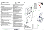
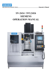
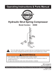
HANDLEIDING
Joy Sport
Concept Air Power
Joy Sport Importeur
Fitness-Import
Timmermannsweg 46
5813 AP Ysselsteyn (LB)
[email protected]
www.joysport.nl
Geachte klant,
Wij feliciteren u met de aankoop van dit JOY SPORT product.
Tevens wensen wij u veel sportplezier toe met uw goede keuze.
Volg aandachtig de montage handleiding.
Mocht u nog vragen hebben dan helpen wij u graag verder.
Garantie,
Deze garantie geldt gedurende 12 maanden voor elke fabricagefout aan uw JOY
SPORT product die door een JOY SPORT dealer werd verkocht.
Wanneer u garantie claimt bied JOY SPORT de mogelijkheid om naar eigen
goeddunken het defecte apparaat of het betreffende onderdeel te herstellen of te
vervangen.
De transportkosten van en naar onze werkplaats worden uitgesloten van deze
garantie, en zijn dus voor rekening van de bezitter van het product.
Wanneer u aanspraak wenst te maken op garantie gaat u met het aankoopbewijs
naar de dealer waar u uw product heeft gekocht.
De dealer zal uw claim dan verder afhandelen.
Garantie uitsluitingen,
De garantie geldt niet voor: de normale slijtage, de gevolgen van een ondeskundige
handeling, of beschadiging door de koper of door derden zelf, en defecten die aan
extreme omstandigheden te wijten zijn.
De garantie kan ook niet worden geclaimd wanneer de originele constructie of
uitrusting werd gewijzigd, of wanneer geen originele JOY SPORT onderdelen voor
de reparatie werden gebruikt.
De fabrikant kan niet verantwoordelijk gesteld worden voor schade, verlies of kosten,
direct of indirect ten gevolg van gebruik van dit apparaat.
Fitness-Import
Timmermannsweg 46
5813 AP Ysselsteyn (LB)
[email protected]
www.joysport.nl
2
Montage
Het monteren van Uw roeier
Volg deze instructies aandachting bij het monteren van Uw concept II.
Gereedschap wat nodig is bij het afmonteren van UW roeier (Niet inbegrepen).
Verstelbare sleutel
Hamer
Schroevendraaier
Tang
Plaats de bouten en
schroeven naast de
liniaal om tezienwelke
U nodig heeft.
Onderdelen overzicht
Inbusbout
Parker
Kruiskop bout
Slotbout
Borgmoer
Ring
3
Moer
Controle lijst
4
Montage instructies
Stap 1
Montage van de voor stabilisator
a). Monteer de voor stabilisator (2) op het hoofdframe (1) En zet het vast met twee bouten (60),twee
ringen (6) ,twee veerringen (65) en twee moeren (66).
BELANGRIJK: Zorg er voor dat U alle bouten en moeren goed vast zet.
5
Stap 2
Montage van de zitting geleider.
a)
b)
Monteer de zitting geleider (29) op de houder (32) aan het hoofdframe (1) gebruik hiervoor
bout (34) , ring (6) en borgmoer. (5) om dit vast te zetten.
Doe nu de zitting geleider omhoog (29) en maak het elastiek koord vast (19) aan het nylon koord
(50) let wel op wikkel het nylon koord maar 1 keer om het wiel, en doe daarna de zitting geleider
(29) weer omlaag.
.
6
Stap 3
Montage van de achter stabilisator
a). Monteer de achter satbilisator (3) op de zitting geleider (29) Gebruik bout (9), ring (6) ,
borgmoer (5) om dit vast te zetten,draai hierna de knop (7) vast.
7
Stap 4
Montage van de pedalen
a)
b)
c)
Monteer de pedal as door het mainframe (1).
Monteer de pedalen (37) en de pedal busjes (36) op de pedal as (42) (pedal busjes en pedalen)
vast zetten met ringen (36) en borgmoeren (35).
Plaats kabeltje (72) in de computer (71), druk nu de computer (71) in de daarvoor bestemde
houder (73).
Stap 5
Montage van de zitting.
a)
b)
c)
Monteer de zitting (28) op de zitting geleider (29).
Monteer de aanslag dopjes (13) in het einde van de zitting geleider (29).
Monteer de beschermkap (12) in de achterkant van de zitting geleider (29).
8
Onderdelen overzicht
9
Opklapbaar maken
10
Onderdelen lijst
NR
1
2
3
4
5
6
7
8
9
10
11
12
13
14
15
16
17
18
19
20
21
22
23
24
25
26
27
28
29
30
31
32
33
34
35
36
37
38
39
40
41
42
43
44
45
46
47
Beschrijving
Hoofdframe
Voor stabilisator
Achter stabilisator
Achter stabilisator kapje
Borgmoer M8x1.25Px8H
Ring φ16xφ8.4x1.0t
Knop M8
Achter stabilisator houder
Slotbout M8x1.25Px72L
Afstand busje φ13xφ8.4x20H
Elastiek geleider
Beschermkap
Aanslag dopjes φ25xM8x13L
Moer M8x1.25Px6H
Bout M8x1.25Px60L
Borgmoer M8x1.25Px6H
Kruisschroef M6x1.0Px12L
Elastiek koord
Elastiek koord
Haak
Moer M6x1.0Px4H
Kruisschroef M6x1.0Px20L
Afstands busje φ12xφ8.4x8H
PU wieltje
Lager
Kruisschroef M6x1.0Px12L
Zitting houder
Zitting
Zitting geleider
Houder
Borgmoer M10x1.5px7H
Houder
Bout M8x1.25Px15L
Bout M8x1.25Px135L
Borgmoer 3/8"x16Wx12H
Ring φ21xφ11x2.5t
Pedaal
Pedaalband
Plastic busje
Afstandsbusje
Pen
Pedaal as
Busje
As
Schroef
Crank
Ketting
Aantal
NR
1
1
1
2
10
5
2
1
1
2
1
1
3
3
1
3
3
1
1
1
2
1
6
6
6
4
1
1
1
2
1
1
4
2
2
2
2
2
2
2
1
1
3
1
4
1
1
48
49
50
51
52
53
54
55
56
57
58
59
60
61R/L
62
63
64
65
66
67
68
69
70
71
72
73
74
75
76
77
78
79
80
81
82
83
84
85
86
87
88
89
90
91
92
93
11
Beschrijving
Pulley
Borgmoer M6x1.0px6H
Nylon koord
Koord geleider
Moer 3/8"x26Wx17.6H
Ring φ26x11x2.0t
Schroef M5x15L
Beschermkap
Trektouw
Afdichtdopje
Foam
Stuur
Bout M8x1.25Px55L
Voor stabilisator kapje
Afdichtdop
Voor stabilisator wieltje
Asje
Veerring M8
Moer M8x1.25Px15.5H
Dopje
Bout M4x16L
Beschermkap
Grote beschermkap
Computer
Sensor
Computer beschermkap
Moer 3/8"x26wx9H
Vliegwiel versteller
Afstandsbusje φ16xφ10x7t
Magneet
Busje
Vliegwiel
Busje
Lager
As 3/8"x26Wx145L
Moer 3/8"x26wx4H
GUIDER
Vliegwiel beschermkap
Afstandsbusjes φ15xφ8.2x45L
Schroef M5x75L
Afstandsbusje
Boet M10x1.5Px55L
Afstandsbusje φ16xφ10x11L
Druk wiel
Pulley beschermkap
Bout M4x12L
Aantal
1
4
1
1
2
2
7
1
1
2
2
1
2
2
2
2
2
2
3
1
4
2
2
1
1
1
4
2sets
1
1
1
1
1
1
1
1
1
3
5
6
1
1
1
1
1
4
Computer handleiding
Het gebruik van Uw computer.
De computer geeft de volgende 5 functies weer. (Tijd, Snelheid, afstand, calorieverbruik en
scan).
1) Snelheid kan weergegeven worden in miles of kilometers per uur.
2) Afstand kan weergegeven worden van 0.1 tot 9999 miles of kilometers.
3) Tijd wordt weergegeven in uren: minuten: seconden met een maximum van 23 uur: 59
minuten: 59 seconden.
4) Calorieverbruik wordt weergegeven van 1-9999 calorieën.
5) SCAN is de functie die om de 4 seconde U de gegevens zal tonen zoals tijd, afstand,
snelhied en calorieverbruik.
6) De computer zal automatisch na 4 minuten uitschakelen als U de roeier niet gebruikt, ook
zal de computer weer automatisch inschakelen als U de roeier weer in gebruik neemt.
1) Houdt de knop 4 seconde vast om de computer te resetten.
2) Als U de batterijen de eerste keer installeert zal de computer opstarten in scan mode.
12
Bereken zelf uw maximale hartslag:
De computer kan ingesteld worden van minimaal 60 hartslagen tot maximaal 220 hartslagen
per minuut.
220 minus uw leeftijd is uw maximale hartslag.
60% tot 70% van uw maximale hartslag is de beste vetverbranding zone.
70% tot 90% van uw maximale hartslag is voor conditie verbetering.
Bijvoorbeeld: Iemand is 40 jaar en wil trainen voor vetverbranding (afvallen).
Dan is dit 220 minus 40 is 180 MAXIMALE HARTSLAG.
180 X 60% is 108 en 180 X 70% is 126.
Ideale vetverbranding voor deze persoon ligt dus tussen de 108 en 126
hartslagen per minuut.
Pakt U met de palmen van de handen beide hartslag sensoren vast en begint u met fietsen.
De computer zal een alarm geven als U boven uw maximale hartslag komt en het alarm zal
pas weer stoppen als uw hartslag weer op het gewenste niveau zit.
(Optioneel)
Ook verkrijgbaar is de draadloze hartslagband van JOY SPORT.
Wanneer U deze band draagt tijdens Uw training hoeft U de handgrepen niet vast te
houden.
De draadloze hartslagband zal Uw hartslag doorgeven aan de computer.
Informeer bij Uw JOY SPORT dealer naar deze hartslagband.
USER MANUAL
Joy Sport
Concept Air Power
Joy Sport Importer
Fitness-Import
Timmermannsweg 46
5813 AP Ysselsteyn (LB)
[email protected]
www.joysport.nl
Dear customer,
We want to thank you for having chosen a JOY SPORT product, and wish you a lot
of fun and success during training with your JOY SPORT exercisers.
Please note and follow the enclosed safety and assembly instructions carefully.
If you have questions please do not hesitate to contact us.
Guarantee,
This guarantee covers all manufacturing and material flaws on JOY SPORT products
purchased from an authorized JOY SPORT dealer for a period of 12 months from
purchase.
If you wish to make a claim under the guarantee, JOY SPORT shall be entitled to
repair or replace the defective unit or part at its discretion.
The owner of the unit must pay for the transport costs and any dealer's workshop
costs.
To make a claim under the guarantee, take your guarantee card to your dealer.
The dealer will then take the necessary action.
If this is not possible, contact your national JOY SPORT importer.
The following are not covered by the guarantee : normal wear and tear and the
consequences of improper treatment or damage caused by the purchaser or third
persons and faults which are due to other circumstances.
Claims may not be made under the guarantee if modifications have been made to
the original construction or equipment or if JOY SPORT original parts were not used
to repair the unit.
In no event the manufacturer shall be liable for incidental or
consequential losses, damages or expenses in connection with exercise products.
Fitness-Import
Timmermannsweg 46
5813 AP Ysselsteyn (LB)
[email protected]
www.joysport.nl
2
ASSEMBLY
Assembling Your Air Bike
GENERAL
Remove all the parts of your rower from the carton
and place them on the floor carefully.
Assembling your rower is simple!
Follow these instructions carefully and it should take
you around 20-25 minites.
TOOLS REQUIRED FOR ASSEMBLY (NOT SUPPLIED)
Adjustable Wrench
Hammer
Phillips Screwdriver
INCHES
Pliers
Place bolt or screw on
ruler to find length in
inches or millimeters.
Place washer, end of
bolt, or screw on circles
to find size in inches or
millimeters.
MILLIMETERS
HARDWARE ILLUSTRATIONS
3
Check-List
4
ASSEMBLY INSTRUCTIONS
Step 1
ATTACH THE FRONT STABILIZER
a). Attach the Front Stabilizer (2) to the Main Frame (1) and secure, using two carriage bolts
(60), two flat washers (6) ,two spring washers (65) and two capnuts (66) and tighten.
NOTE: Make sure our fasten the stabilizer with built in wheel.
5
Step 2
ATTACH THE ALUMINUM TRACK
a)
b)
Attach the Aluminum Track (29) with bracket (32) to the Main Frame (1) bracket and secure,
using allen head bolt (34) , washer (6) and locknut. (5).
Raise up the Aluminum Track (29) and connect the elastic cord (19) from the inside of the
track (29) to the front strap (50) through the Main Frame (1) bracket with hook (20) then put
the track (29) down.
.
6
Step 3
ATTACH THE REAR STABILIZER
a). Attach the Rear Stabilizer (3) to the Rear Stabilizer Bracket (8) and secure, using allen
head bolt (9), washer (6) , locknuts (5) and rear adjustment knob (7) and tighten.
7
Step 4
ATTACH THE PEDALS
a)
b)
c)
Thread the pedal rod through the tube on the main frame (1).
Slide the pedals (37) and spacers (36) onto the pedal axle (42) (spacer inside, the pedal) and
fasten with washers (36) and locknuts (35).
Connect the socket of sensor (72) to the plug of computer (71), then press the Computer (71)
into position on the console (73).
Step 5
ATTACH THE SEAT TO THE SEAT CARRIAGE
a)
b)
c)
Attach the Seat (28) onto the aluminum track (29) for both sides.
Insert the end stoppers (13) to the end holes of track (29).
Attach the track end cap (12) to the rear end of the aluminum track (29).
8
Explosion Drawing
9
Assembly Instruction
10
Part List
NO
1
2
3
4
5
6
7
8
9
10
11
12
13
14
15
16
17
18
19
20
21
22
23
24
25
26
27
28
29
30
31
32
33
34
35
36
37
38
39
40
41
42
43
44
45
46
47
Description
FRAME
FRONT STABILIZER
REAR STABILIZER
END CAP
LOCK NUT M8x1.25Px8H
FLAT WASHERφ16xφ8.4x1.0t
KNOB M8
REAR STABILIZER FIXER
ALLEN SCREW M8x1.25Px72L
SPACERφ13xφ8.4x20H
ELASTIC CORD FIXING WHEEL
END CAP
STOPPERφ25xM8x13L
NUT M8x1.25Px6H
ALLEN BOLT M8x1.25Px60L
LOCK NUT M8x1.25Px6H
PHILIPS SCREW M6x1.0Px12L
ELASTIC CORD
ELASTIC CORD
C HOOK
NUT M6x1.0Px4H
PHILIPS SCREW M6x1.0Px20L
SPACERφ12xφ8.4x8H
PU WHEEL
BEARING
PHILIPS SCREW M6x1.0Px12L
SEAT CARRIAGE
SEAT
ALUMINUM TRACK
BRACKET
LOCK NUT M10x1.5px7H
CONNECTER
ALLEN SCREW M8x1.25Px15L
ALLEN BOLT M8x1.25Px135L
LOCK NUT3/8"x16Wx12H
FLAT WASHERφ21xφ11x2.5t
PEDAL
PEDAL STRAP
PLASTIC SLEEVE
SPACER
PIN
PEDAL AXLE
BUSHING
AXLE
SCREW M6x1.0Px30L
CRANK
CHAIN
Q’ty
1
1
1
2
10
5
2
1
1
2
1
1
3
3
1
3
3
1
1
1
2
1
6
6
6
4
1
1
1
2
1
1
4
2
2
2
2
2
2
2
1
1
3
1
4
1
1
NO
48
49
50
51
52
53
54
55
56
57
58
59
60
61R/L
62
63
64
65
66
67
68
69
70
71
72
73
74
75
76
77
78
79
80
81
82
83
84
85
86
87
88
89
90
91
92
93
Description
PULLEY
LOCK NUT M6x1.0px6H
STRAP
BELT FIXER
CAP NUT3/8"x26Wx17.6H
FLAT WASHERφ26x11x2.0t
MACHING SCREW M5x15L
DECORATION COVER
ROPE
END CAPφ1"
FOAM
HANDLEBAR
CARRIAGE BOLT M8x1.25Px55L
FOOT-CAP
FOOT-CAP
FOOT-CAP WHEEL
FOOT-CAP WHEEL AXLE
SPRING WASHER M8
CAP NUT M8x1.25Px15.5H
FIXING PLUG
ROUND MACHINE SCREW M4x16L
FAN COVER CAP
FAB COVER
MONITOR
SENSOR
FRAME PROTECTING CAP
NUT3/8"x26wx9H
FAN WHEEL ADJUSTOR M6x50L
SPACERφ16xφ10x7t
MAGNET
BUSHING
FAN WHEEL
BUSHING
ONE-WAY BEARING
AXLE3/8"x26Wx145L
NUT3/8"x26wx4H
GUIDER
FAN COVER SLEEVE
PLASTIC SPACERφ15xφ8.2x45L
ROUND MACHINE SCREW M5x75L
ELASTIC CORD SPACER
ALLEN BOLT M10x1.5Px55L
SPACERφ16xφ10x11L
PRESSING WHEEL
PULLEY COVER
PHILIPS SCREW M4x12L
Q’ty
1
4
1
1
2
2
7
1
1
2
2
1
2
2
2
2
2
2
3
1
4
2
2
1
1
1
4
2sets
1
1
1
1
1
1
1
1
1
3
5
6
1
1
1
1
1
4
COMPUTER MONITOR INSTRUCTIONS
11
Using Your Monitor:
Your MONIOR is designed to provide five functions (Tune, Speed, Distance, Calories and Scan).
1) SPEED can be displayed in either “Miles” or “KM” per hour.
2) DISTANCE is displayed from 0.1-9999 miles or km.
3) TIME is displayed in hours: minutes: seconds up to 23 hours: 59 minutes: 59 seconds.
4) CALORIES is displayed 1-9999 KCAL.
5) SCAN sequentially displays Times, Distance and Calories to help you monitor each function.
6) The monitor will shut off itself. If no movement is detected for 4 minutes.
To turn the monitor “ON”
1) Press the ‘Mide/Reset’ button for 2 seconds to clear the monitor.
2) The monitor will automatically turn on as your begin to pedal.
3) Initial start up will be in SCAN mode.
To Set Miles or Kilometers
1) Flip to switch on back of the monitor to desired setting.
2) Take one battery out from the case.
3) Now replace the battery back into the case.
4) Your monitor will be in the mode of measurement selected.
To View “Time” Only
1) Selectively press the “Mode/Reset” button until “D” appears in the display.
2) You are now in “Time” function. The “SCAN” function has ben disengaged.
To View “SPEED”
1) Speed is automatically displayed as you begin to pedal.
To View “Distance” Only
1) Selectively press the “Mode/Select” button until “D” appears in the display.
2) You are now in “Distance” funtion. The “SCAN” function has been disengaged.
To view “CALOEIES” Only
1) Selectively press the “Mode/Reset” button until “C” appears in the display.
2) You are now in “DISTANCE” function. The “SCAN” function has been disengaged.
3) Caloris are calculated based on the speed of pedaling and the duration of the time-Calories
burned will automatically stop when you stop pedaling.
To View by Using “SCAN”
1) Selectively press the “Mode/Reset” button until “{}” appears in the display.
2) You are now in “SCAN” MODE.
3) You may also reset your monitor at any time by pressing and holding the “Mode/Reset”
button. This will automatically place you in “SCAN” mode.
To Reset your Monitor
1) To reset or clear your monitor, simply press and hold the “Mode/Reset” button for 2
seconds.
2) Your monitor is now reset and all functions will appear as zero until you begin your
workout.
12