1
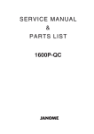
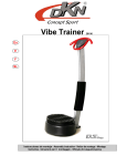
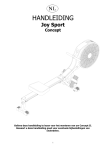
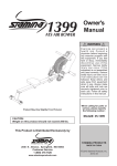
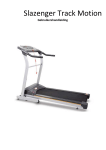
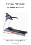
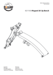
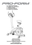
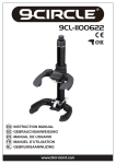
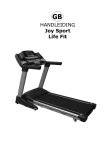
HANDLEIDING
Joy Sport
Concept Air Power
Joy Sport Importeur
Fitness-Import
Timmermannsweg 46
5813 AP Ysselsteyn (LB)
[email protected]
www.joysport.nl
Geachte klant,
Wij feliciteren u met de aankoop van dit JOY SPORT product.
Tevens wensen wij u veel sportplezier toe met uw goede keuze.
Volg aandachtig de montage handleiding.
Mocht u nog vragen hebben dan helpen wij u graag verder.
Garantie,
Deze garantie geldt gedurende 24 maanden voor elke fabricagefout aan uw JOY
SPORT product die door een JOY SPORT dealer werd verkocht.
Wanneer u garantie claimt bied JOY SPORT de mogelijkheid om naar eigen
goeddunken het defecte apparaat of het betreffende onderdeel te herstellen of te
vervangen.
De transportkosten van en naar onze werkplaats worden uitgesloten van deze
garantie, en zijn dus voor rekening van de bezitter van het product.
Wanneer u aanspraak wenst te maken op garantie gaat u met het aankoopbewijs
naar de dealer waar u uw product heeft gekocht.
De dealer zal uw claim dan verder afhandelen.
Garantie uitsluitingen,
De garantie geldt niet voor: de normale slijtage, de gevolgen van een ondeskundige
handeling, of beschadiging door de koper of door derden zelf, en defecten die aan
extreme omstandigheden te wijten zijn.
De garantie kan ook niet worden geclaimd wanneer de originele constructie of
uitrusting werd gewijzigd, of wanneer geen originele JOY SPORT onderdelen voor
de reparatie werden gebruikt.
De fabrikant kan niet verantwoordelijk gesteld worden voor schade, verlies of kosten,
direct of indirect ten gevolg van gebruik van dit apparaat.
Fitness-Import
Timmermannsweg 46
5813 AP Ysselsteyn (LB)
[email protected]
www.joysport.nl
2
Montage instructies
STAP 1
Verwijder de kartonnen rol die aan de roeier is gemonteerd door de bouten en moeren te
demonteren.
STAP 2
Er is een buckle bevestigd aan het trekkoord (24), om te voorkomen dat tijdens het transport
Het trekkoord in de roeier schiet.
Verwijder de buckle door onderstaande stappen te volgen.
Volg de stappen in de tekeningen om de buckle te verwijderen.
STAP 3
Zorg er voor dat de transportwieltjes van de voorsteun (7) naar de voorkant wijzen.
Monteer de voorsteun (7) aan het hoofdframe (1) met Slotbouten (M8x1.25x65mm) (71),
gebogen ringen (M8) (35), Veerringen (M8) (34), en dopmoeren (M8x1.25)(33).
STEP 4
Monteer de C clip (48) Op de voetpedaal buis (6). Monteer het lange gedeelte van de voetpedaal buis (6)
door het hoofdframe (1). Verzeker de voetpedaal buis (6) in de positie met de clip (46).
STEP 5
De linker voetplaat is gemarkeerd met de letter L (43L), en de rechter voetplaat met de letter R (43R).
Monteer de voetplaathouder (45) door de gaten in het hoofdframe (1).
Plaats de linker voetplaat (43L) aan de linkerkant op de voetplaathouder (45) en plaats de rechter voetplaat
(43R) op de rechterkant van de voetplaathouden (45), en schuif deze tegen het hoofdframe (1) aan.
Zet de voetplaten (43L, 43R) vast met ringen (M8) (42), veerringen (M8) (34), en dopmoeren
(M8x1.25x15mm) (41) aan beide kanten van de voetplaathouder (45). TIP: U heeft twee sleutes nodig om
de dopmoeren (M8x1.25x15mm) (41) vast te zetten aan beide kanten omdat deze anders meedraaien.
STEP 6
Schuif de zitting (66) Op de rails (2). Monteer de stop bumper (56) op de rails (2)
met de inbusbouten (M8x1.25x25mm) (22).
Controleer ook of de stop bumper (56) die al vanaf de fabriek is voor gemonteerd vast zit.
Mocht deze stop bumper er onverhoopt niet opzitten monteer deze dan zelf.
STEP 7
Monteer de achter standaard (3) aan de rails (2) met bout (M8x1.25x15mm) (59)
en veerring (M8)(34) aan de binnenkant van de rails (2) en twee inbusbouten (M8x1.25x15mm) (57) van de
onderkant.
Zet alle bouten pas vast als ze allemaal gemonteerd zijn.
Druk nu het rail kapje (53) in de achterkant van de rails (2).
STEP 8
Monteer de rails (2) aan het hoofdframe (1) met inbusbouten (M10x1.5x100mm) (55), Ringen (M10) (52),
en dopmoeren (M10x1.5) (51). Vergrendel de rails (2) in de positie met de twee pinnen (54).
STEP 9
Monteer de twee AA batterijen in de computer (67), de batterijen worden niet bijgeleverd.
Bevestig de sensor kabel (68) in de computer (67).
Monteer de computer (67) in de opening van de kappen (10, 84).
Computer handleiding
Het gebruik van Uw computer.
De computer geeft de volgende 5 functies weer. (Tijd, Snelheid, afstand, calorieverbruik en
scan).
1) Snelheid kan weergegeven worden in miles of kilometers per uur.
2) Afstand kan weergegeven worden van 0.1 tot 9999 miles of kilometers.
3) Tijd wordt weergegeven in uren: minuten: seconden met een maximum van 23 uur: 59
minuten: 59 seconden.
4) Calorieverbruik wordt weergegeven van 1-9999 calorieën.
5) SCAN is de functie die om de 4 seconde U de gegevens zal tonen zoals tijd, afstand,
snelhied en calorieverbruik.
6) De computer zal automatisch na 4 minuten uitschakelen als U de roeier niet gebruikt, ook
zal de computer weer automatisch inschakelen als U de roeier weer in gebruik neemt.
1) Houdt de knop 4 seconde vast om de computer te resetten.
2) Als U de batterijen de eerste keer installeert zal de computer opstarten in scan mode.
Onderdelen diagram
Onderdelenlijst
Onderdeel Nr.
1
2
3
4
5
6
7
8
9
10
11
12
13
14
15
16
17
18
19
20
21
22
23
24
25
26
27
28
29
30
31
32
33
34
35
36
37
38
39
40
41
42
43
44
45
46
47
48
49
50
51
52
53
54
Beschrijving
Hoofdframe
Rails
Achter standard
Zitting houder
Foam afstandshouder
Stopper
Voor standaard
Eindkapje
Schroef (M4 x 12mm)
Linker kap
Schroef (M5 x 15mm)
Schroef (M5 x 25mm)
Schroef (M5 x 70mm)
Foam
Rond eindkapje
Stuur
Busje
Borgmoer (M8 x 1.25mm)
Lager (698z)
Trekkoord roller
Afstandsbusje (8.2 x 10.5 x 26.2mm)
Inbusbout (M8 x 1.25 x 25mm)
Inbusbout M8 x 1.25 X 57mm)
Trekkoord
Multiriem
Lager (6000z)
Pulley
Schroef (M5 x 0.8 x 12mm)
Busje
Vliegwielafdekking
Vliegwiel
Borgmoer (M5 x 0.5)
Dopmoer (M8 x 1.25)
Veerring (M8)
Gebogen ring (M8)
Lager (6903z)
Meeneemlager (HF1716)
Lager behuizing
Binnen C ring (30mm)
As
Inbusbout (M8 x 1.25 x 15mm)
Ring (M8)
Voetplaat (L+R)
Voetplaat strap
Voetplaathouder
Veerclip
Busje
C ring (12.7mm)
C ring (10mm)
Foam
Dopmoer
Ring (M10)
Eindkapje
Pin
Aantal
1
1
1
1
3
1
1
2
6
1
6
1
1
2
2
1
1
1
2
1
1
4
1
1
1
3
1
12
1
1
1
8
2
5
2
2
2
1
1
1
2
2
2
2
1
1
2
1
2
1
1
1
1
2
55
56
57
58
59
60
61
62
63
64
65
66
67
68
69
70
71
72
73
74
75
76
77
78
79
80
81
82
83
84
85
86
87
88
89
90
91
92
93
94
95
96
97
98
99
100
101
102
103
104
105
106
107
108
109
Inbusbout (M10 x 1.5 x 100mm)
Stop bumper
Bout (M8 x 1.25 x 15mm)
Ovaal eindkapje (30mm x 60mm)
Bout (M8 x 1.25 x 15mm)
Afstansbusje
Wieltje
Asje
Borgmoer (M10 x 1.5 x 7mm)
Bout (M10 x 1.5 x 105mm)
Bout (M6 x 1 x 15mm)
Zitting
Computer
Sensorkabel
Schroef (M5 x 8mm)
Magneet
Slotbout (M8 x 1.25 x 65mm)
Moer (3/8’’-26 x 7mm)
Rubber voetje
Ring (M6)
Schroef (M5 x 12mm)
Foam
Borgmoer
Ring
Nylon ring
Plaatje
C rinf (17mm)
Nylon ring
Beschermkapje
Rechter kap
Sensor clip
Moer
Bout (M6 x 1 x 35mm)
Spanner
Moer (M6 x 1)
Schroef (M3 x 12mm)
Afdekplaat veerpakket
Moer
Veerhouder
Veerbus
Schroef (M4 x 0.7 x 6mm)
Veer
Pulley as
Veerbox
Multiriem Pulley
C ring (9mm)
Ring
Schroef (M5 x 0.8 x 12mm)
Disk
Ring
Waarschuwings label
Sleutel
Inbussleutel (5mm)
Inbussleutel (6mm) met schroevendraaier
Handleiding
1
2
2
2
1
6
6
3
3
3
4
1
1
1
1
1
2
5
2
2
2
2
2
4
2
1
1
1
2
1
1
2
2
2
2
2
1
2
1
1
1
1
1
1
1
1
1
2
1
2
1
1
1
2
1
USER MANUAL
Joy Sport
Concept Air Power
Joy Sport Importer
Fitness-Import
Timmermannsweg 46
5813 AP Ysselsteyn (LB)
[email protected]
www.joysport.nl
Dear customer,
We want to thank you for having chosen a JOY SPORT product, and wish you a lot
of fun and success during training with your JOY SPORT exercisers.
Please note and follow the enclosed safety and assembly instructions carefully.
If you have questions please do not hesitate to contact us.
Guarantee,
This guarantee covers all manufacturing and material flaws on JOY SPORT products
purchased from an authorized JOY SPORT dealer for a period of 24 months from
purchase.
If you wish to make a claim under the guarantee, JOY SPORT shall be entitled to
repair or replace the defective unit or part at its discretion.
The owner of the unit must pay for the transport costs and any dealer's workshop
costs.
To make a claim under the guarantee, take your guarantee card to your dealer.
The dealer will then take the necessary action.
If this is not possible, contact your national JOY SPORT importer.
The following are not covered by the guarantee : normal wear and tear and the
consequences of improper treatment or damage caused by the purchaser or third
persons and faults which are due to other circumstances.
Claims may not be made under the guarantee if modifications have been made to
the original construction or equipment or if JOY SPORT original parts were not used
to repair the unit.
In no event the manufacturer shall be liable for incidental or
consequential losses, damages or expenses in connection with exercise products.
Fitness-Import
Timmermannsweg 46
5813 AP Ysselsteyn (LB)
[email protected]
www.joysport.nl
BEFORE YOU BEGIN
Thank you for choosing the Air Rower
. We
take great pride in producing this quality product
and hope it will provide many hours of quality
exercise to make you feel better, look better, and
enjoy life to its fullest.
It's a proven fact that a regular exercise program
can improve your physical and mental health.
Too often, our busy lifestyles limit our time and
opportunity to exercise. The Air Rower
provides a convenient and simple method to begin
your assault on getting your body in shape and
achieving a happier and healthier lifestyle.
Before reading further, please review the
drawing below and familiarize yourself with the
parts that are labeled.
Read this manual carefully before using the
Air Rower
.
Although ZH construct its products with
the finest materials and uses the highest standards
of manufacturing and quality control, there can
sometimes be missing parts or incorrectly sized
parts. If you have any questions or problems with
the parts included with your Air Rower please
do not return the product. Contact us FIRST!
Be sure to have the name and model number of
the product available when you contact us.
Meter
Handlebar
Left Cover
Right Cover
Pedal Cap
Front Stabilizer
Seat
Rail
Pedal Strap
Pedal Cap
Warning Label
Pull Pins
Seat Carriage
Oval Endcap
Rear Stand
THE FOLLOWING TOOLS ARE INCLUDED FOR ASSEMBLY :
Wrench
Allen Wrench (5mm)
4
Allen Wrench (6mm)
HARDWARE IDENTIFICATION CHART
This chart is provided to help identify the hardware used in the assembly process. Place the washers or
the ends of the bolts or screws on the circles to check for the correct diameter. Use the small scale to
check the length of the bolts and screws.
3/16"
1/4"
5/16"
3/8"
1/2"
INCHES
0
0
1/2
10
1
20
1/2
30
40
2
50
1/2
60
3
70
1/2
80
4
1/2
5
1/2
90 100 110 120 130 140 150
MILLIMETERS
6
8
10
6
in.
mm.
length
12
NOTICE: The length of all bolts and screws, except those with flat
heads, is measured from below the head to the end of the bolt
or screw. Flat head bolts and screws are measured from the
top of the head to the end of the bolt or screw.
length
After unpacking the unit, open the hardware bag and make sure that you have all the following items.
Some hardware may be already attached to the part.
Part Number and Description
Qty
22
41
Bolt, Button Head (M8 x 1.25 x 25mm)
Bolt, Button Head (M8 x 1.25 x 15mm)
2
2
33
51
Acorn Nut (M8 x 1.25)
Acorn Nut (M10 x 1.5)
2
1
34
Lock Washer (M8)
5
35
Arc Washer (M8)
2
42
52
Washer (M8)
Washer (M10)
2
1
55
Bolt, Button Head (M10 x 1.5 x 100mm)
1
57
Bolt, Flat Head (M8 x 1.25 x 15mm)
2
59
Bolt, Hex Head (M8 x 1.25 x 15mm)
1
71
Carriage Bolt (M8 x 1.25 x 65mm)
2
6
ASSEMBLY INSTRUCTIONS
Place all parts from the box in a cleared area and position them on the floor in front of you. Remove
all packing materials from your area and place them back into the box. Do not dispose of the
packing materials until assembly is completed. Read each step carefully before beginning.
NOTE: There are some packing parts attached on the Air Rower. Please follow the steps below
to remove them before any assembly. These parts are only for packing, do not dispose of the
packing materials until assembly is completed.
STEP 1
Remove the CARDBOARD ROLLER from the front of the MAIN FRAME(1) by removing the SCREWS
and WASHERS.
STEP 2
A BUCKLE has been attached to the STRAP(24) to prevent the STRAP(24) from returning into the main
body of the 1399 Air Rower during shipping. Remove the BUCKLE by following these steps:
1. Refer to detail view 1. Pull the STRAP(24) away from the main body about 8 inches. Use one hand to
hold the STRAP(24) at position A while using the other hand to pull the STRAP(24) loop on the top of
the BUCKLE to the position as shown in detail view 2.
2. Refer to detail view 2. Continue to hold the STRAP(24) at position A. Pull the STRAP(24) from
position B until the STRAP(24) is completely removed from the BUCKLE. Make sure the STRAP(24)
isn't twisted and let it return into the main body of the 1399 Air Rower. The STRAP(24) will hold the
HANDLEBAR(16) taut against the MAIN FRAME(1).
1.
2.
Buckle
A
Buckle
A
B
Cardboard Roller
Buckle
Screws
7
Washers
ASSEMBLY INSTRUCTIONS
STEP 3
Make sure the Wheels on the FRONT STABILIZER(7) face the front. Attach the FRONT STABILIZER(7)
to the MAIN FRAME(1) with CARRIAGE BOLTS(M8x1.25x65mm)(71), ARC WASHERS(M8)(35), LOCK
WASHERS(M8)(34), and ACORN NUTS(M8x1.25)(33).
Wheel
Wheel
8
ASSEMBLY INSTRUCTIONS
STEP 4
Locate the C Ring(48) on the STOPPER BAR(6). Insert the longer end of the STOPPER BAR(6) through
the MAIN FRAME(1). Secure the STOPPER BAR(6) in position with the SPRING CLIP(46).
STEP 5
There is an “L” decal on the LEFT PEDAL CAP(43L), and an “R” decal on the RIGHT PEDAL CAP(43R).
Insert the PEDAL SHAFT(45) through the holes on the MAIN FRAME(1). Place the LEFT PEDAL
CAP(43L) onto the left end of the PEDAL SHAFT(45) and place the RIGHT PEDAL CAP(43R) onto
the right end of the PEDAL SHAFT(45), and slide them toward the MAIN FRAME(1). Then secure the
PEDAL CAPS(43L, 43R) with WASHERS(M8)(42), LOCK WASHERS(M8)(34), and BUTTON HEAD
BOLTS(M8x1.25x15mm)(41) at both sides of the PEDAL SHAFT(45).
NOTE: You need to use two Allen wrenches to tighten the BUTTON HEAD BOLTS(M8x1.25x15mm)(41)
at both ends of the PEDAL SHAFT(45) at the same time.
L
R
9
ASSEMBLY INSTRUCTIONS
STEP 6
Slide the SEAT(66) onto the RAIL(2). Attach the STOPPER BUMPER(56) to the RAIL(2) with BUTTON
HEAD BOLTS(M8x1.25x25mm)(22). Also, please verify that the other STOPPER BUMPER(56) have already
been assembled at the factory. If it has not been pre-assembled, then please assemble at this time.
STEP 7
Attach the REAR STAND(3) to the RAIL(2) with a HEX BOLT(M8x1.25x15mm)(59) and a LOCK
WASHER(M8)(34) from inside the RAIL(2) and two FLAT HEAD BOLTS(M8x1.25x15mm)(57) from
underneath. Tighten all three bolts only after all three have been started. Press the RAIL CAP(53) into the
back end of the RAIL(2).
(Assembled at the factory)
10
ASSEMBLY INSTRUCTIONS
STEP 8
Attach the RAIL(2) to the MAIN FRAME(1) with BUTTON HEAD BOLT(M10x1.5x100mm)(55),
WASHER(M10)(52), and ACORN NUT(M10x1.5)(51). Lock the RAIL(2) in position with the two LOCKING
PINS(54).
STEP 9
Install two AA batteries into the METER(67), the batteries are not included. See page 12 for detailed battery
installation instructions. Connect the SENSOR WIRE(68) to the METER(67). Press the METER(67) into
the opening in the COVERS(10, 84).
11
OPERATIONAL INSTRUCTIONS
USING THE FITNESS METER
POWER ON : Pull the HANDLEBAR(16) or push the
button.
POWER OFF : Automatic shut off after four minutes of
inactivity.
DIST
TIME
CAL
FUNCTION BUTTON:
Press to select the function value displays of DISTANCE, TIME,
and CALORIES.
Reset all functions to zero by pressing the button and holding
it down for four seconds.
MODE
FUNCTIONS:
SPEED: Displays the current speed on upper display from zero to 999.9 miles per hour.
SCAN: Lower display automatically scans each function of DISTANCE, TIME, and CALORIES
in sequence every six seconds.
DISTANCE: Displays the distance from zero to 99.9 miles.
TIME: Displays the time from one second up to 99:59 minutes.
CALORIES: Displays the calorie consumption from zero to 999.9 Kcal.
The calorie readout is an estimate for an average user. It should be used only as a
comparison between workouts on this unit.
NOTE: The meter will shut off automatically after four minutes of inactivity. All function values will
be kept. Press the MODE button and hold it down for four seconds to reset all functions
to zero.
AA Batteries
HOW TO INSTALL AND REPLACE BATTERIES:
1. Use your hand or a simple tool to pry the METER(67) from the side
covers.
2. The meter operates with two AA batteries, the batteries are not
included. Refer to the illustration to install or replace the batteries.
NOTE:
1. Do not mix a new battery with an old battery.
2. Use the same type of battery. Do not mix an alkaline battery with
another type of battery.
3. Rechargeable batteries are not recommended.
12
FRONT
16
PRODUCT PARTS DRAWING
BACK
PARTS LIST
PART#
1
2
3
4
5
6
7
8
9
10
11
12
13
14
15
16
17
18
19
20
21
22
23
24
25
26
27
28
29
30
31
32
33
34
35
36
37
38
39
40
41
42
43
44
45
46
47
48
49
50
51
52
53
54
55
PART NAME
Main Frame
Rail
Rear Stand
Seat Carriage
Foam Spacer
Stopper Bar
Front Stabilizer
Front Endcap
Screw, Round Head (M4 x 12mm)
Left Cover
Screw, Round Head (M5 x 15mm)
Screw, Round Head (M5 x 25mm)
Screw, Round Head (M5 x 70mm)
Foam Grip
Round Plug (25.4mm)
Handlebar
Sleeve (ø16 x 80mm)
Nylock Nut (M8 x 1.25)
Bearing (698z)
Strap Roller
Spacer Sleeve (ø8.2 x ø10.5 x 26.2mm)
Bolt, Button Head (M8 x 1.25 x 25mm)
Bolt, Button Head (M8 x 1.25 x 57mm)
Strap
V Belt
Bearing (6000z)
Small Belt Pulley
Screw, Round Head (M5 x 0.8 x 12mm)
Strap Bushing
Fan Plate
Fan Wheel
Nylock Nut (M5 x 0.5)
Acorn Nut (M8 x 1.25)
Lock Washer (M8)
Arc Washer (M8)
Bearing (6903z)
One Way Bearing (HF1716)
Bearing Housing
Inner C Ring (30mm)
Fan Axle
Bolt, Button Head (M8 x 1.25 x 15mm)
Washer (M8 x ø22 x 2mm thick)
Pedal Cap
Pedal Strap
Pedal Shaft
Spring Clip
Bushing (ø13 x ø25.4 x 20mm)
C Ring (12.7mm)
C Ring (10mm)
Foam Pad
Acorn Nut (M10 x 1.5)
Washer (M10)
Rail Cap
Pull Pin
Bolt, Button Head (M10 x 1.5 x 100mm)
17
QTY
1
1
1
1
3
1
1
2
6
1
6
1
1
2
2
1
1
1
2
1
1
4
1
1
1
3
1
12
1
1
1
8
2
5
2
2
2
1
1
1
2
2
2
2
1
1
2
1
2
1
1
1
1
2
1
PARTS LIST
PART#
56
57
58
59
60
61
62
63
64
65
66
67
68
69
70
71
72
73
74
75
76
77
78
79
80
81
82
83
84
85
86
87
88
89
90
91
92
93
94
95
96
97
98
99
100
101
102
103
104
105
106
107
108
109
PART NAME
Stopper Bumper
Bolt, Flat Head (M8 x 1.25 x 15mm)
Oval Endcap (30mm x 60mm)
Bolt, Hex Head (M8 x 1.25 x 15mm)
Roller Spacer (ø10.2 x ø16 x 5.5mm)
Roller
Spacer Tube (ø10.2 x ø12 x 66mm)
Nylock Nut (M10 x 1.5 x 7mm Thick)
Bolt, Button Head (M10 x 1.5 x 105mm)
Bolt, Round Head (M6 x 1 x 15mm)
Seat
Meter
Sensor Wire
Screw, Round Head (M5 x 8mm)
Magnet
Carriage Bolt (M8 x 1.25 x 65mm)
Nut (3/8"-26 x 7mm thick)
Rubber Stand
Washer (M6)
Screw, Round Head (M5 x 12mm)
Foam Pad (25 x 25 x 5mm thick)
Nylon Washer (ø17.5 x ø25 x 1 mm thick)
Washer (ø17.2 x ø21 x 1 mm thick)
Nylon Washer (ø10.2 x ø16.5 x 1 mm thick)
Support Plate
C Ring (17mm)
Nylon Washer (ø10.2 x ø16 x 0.5 mm thick)
Protection Cap
Right Cover
Sensor Clip
Flange Nut (3/8"-26)
Eyelet Bolt (M6 x 1 x 35mm)
Tension Bracket
Nut (M6 x 1)
Screw, Round Head (M3 x 12mm)
Spring Box Cover
Thin Nut (3/8"-26, 0.16" thick)
Spring Holder
Spring Core
Set screw (M4 x 0.7 x 6mm)
Spring
Pulley Axle
Spring Box
Belt Pulley
C Ring (9mm)
Washer (ø10.2 x ø13 x 0.5 mm thick)
Screw, Flat Head (M5 x 0.8 x 12mm)
Rubbing Disc
Washer (ø5 x ø11 x 1 mm thick)
Warning Label
Wrench
Allen Wrench (5mm)
Allen Wrench (6mm) w/ Screwdriver
Manual
18
QTY
2
2
2
1
6
6
3
3
3
4
1
1
1
1
1
2
5
2
2
2
2
2
4
2
1
1
1
2
1
1
2
2
2
2
2
1
2
1
1
1
1
1
1
1
1
1
2
1
2
1
1
1
2
1