1
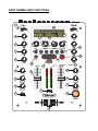
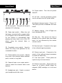
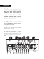
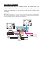
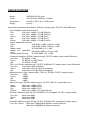
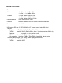
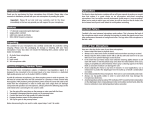
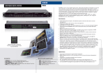
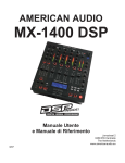
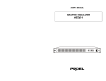
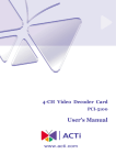
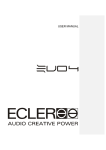
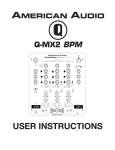
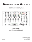
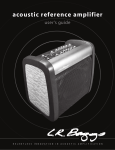
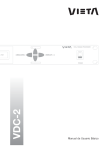
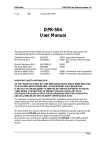
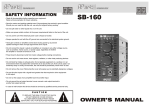
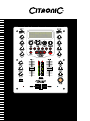
IMPORTANT SAFETY INSTRUCTIONS
1. Read these Instructions.
2. Keep these Instructions.
3. Heed all Warnings.
4. Follow all Instructions.
5. Do not use this apparatus near water.
6. Clean only with a dry cloth.
7. Do not block any of the ventilation openings. Install in accordance with the manufacture’s
instructions.
8. Do not install near nay heat sources such as radiators, heat registers, stoves, or other apparatus
(including amplifiers) that produce heat.
9. Do not defeat the safety purpose of the polarized plug. The wide blade is provided for your safety. If
the provided plug does not fit into your outlet, consult an electrician for replacement of the obsolete
outlet.
10. Protect the power cord from being walked on or pinched particularly at plug, convenience
receptacles, and point where they exit from the apparatus.
11. Only use attachments/accessories specified by the manufacturer.
12. Use only with a cart, stand, tripod, bracket, or table specified by the manufacturer, or
sold with the apparatus. When a cart is used, use caution when moving the
cart/apparatus combination to avoid injury from tip-over
13. Unplug this apparatus during lighting storms or when unused for long periods of time.
14. Refer all servicing to qualified service personnel. Serving is required when the apparatus has been
damaged in any way, such as power-supply cord or plug is damaged, liquid has been spilled or
objects have fallen into the apparatus, the apparatus has been exposed to rain or moisture, does not
operate normally, or has been dropped.
WARNING
To reduce the risk of the fire or electric shock, do not expose this apparatus to rain or moisture. The
apparatus shall not be exposed to dripping or splashing and that no objects filled with liquids, such
as vases, shall be placed on the apparatus.
CAUTION
CAUTION: To reduce the risk of electric shock, do not
remove any cover. No user-serviceable parts inside.
Refer servicing to qualified service personnel only.
The lightning flash with arrowhead symbol within the equilateral triangle is intended to alert
the use to the presence of un-insulated “dangerous voltage” within the product’s enclosure
that may be of sufficient magnitude to constitute a risk of electric shock.
IMPORTANT SAFETY INSTRUCTIONS
The exclamation point within the equilateral triangle is intended to alert the user to the
presence of important operation and maintenance (servicing) instructions in the literature
accompanying this appliance.
CAUTION
To prevent electric shock, do not use this polarized plug with an extension cord, receptacle or other
outlet unless the blades can be fully inserted to prevent blade exposure
FEATURES
• 8 digital effects, 3 digital effects for crossfader
• 3 Kind of channel fader Curve mode
• Big LCD with Back light
• Channel and Crossfader Start function
• Send/Return function
• 3 Band Kill EQ for each channel
• 2 USB Jacks for PC Playback and Recording
• VCA Controlled channel and crossfader
PART NAMES AND FUNCTIONS
1
24
25
2
3
27
26
20
21
23
22
19
3
18
3
15
16
14
17
4
13
6
12
5
11
5
8
10
7
9
PART NAMES AND FUNCTIONS
1. Source input selector switch - These
switches are used to select the input
source assigned to each channel. Each
channel may only be assigned one input
source at a time.
2. Input gain - These knobs are used to
adjust the audio source signal input gain
for a channel. Never use the gain control
to adjust a channels output volume.
Setting the gain level properly will ensure
a clean output signal.
3. Channel EQ control - These knobs are
used to adjust the high, mid and low
range levels of a channel allowing for a
maximum midrange gain of 10dB or
maximum decrease of -35dB. Turning
the knob in a counterclockwise direction
will decrease the amount of high/mid/low
range applied to a channel signal, turning
the knob in a clockwise direction will
increase the amount of high/mid/low
applied to a channel signal.
4. Mic Ievel - Adjusts microphone level.
5. Mic treble/bass EQ - These knobs are
used to adjust the treble (or bass) levels
of the microphone with a maximum
signal gain of 12dB or maximum signal
decrease of -12dB. Turning the knob in a
counterclockwise direction will decrease
the amount of treble (or bass) applied to
the microphone signal, turning the knob
in a clockwise direction will increase the
amount of treble (or bass) applied to
microphone signal.
6. Channel fader - Adjusts the volume for
CH1 and CH2.
7. Mic ON/OFF/Talkover switch - To set
mic on and off, when switch at the
talkover position, the mic on, the sound
level for everything other than mic will
decrease to around 14dB.
8. PFL/Master switch - The position of
this switch will determine the level meter
mode. In the “Master” position, the meter
will detail the out level of the left and right
channels. In the “PFL” position, the left
side of the meter will indicate monaural
level of the PGM.
9. Crossfader - Used to mix the signals
from the 2 channels.
10. FX ON button - This button functions
as an effect Master on/off button and is
used to activate and deactivate the
effects.
11. Cue mixing - Used to preview
channel audio to your headphones.
Listen here before bringing up channel
faders or moving the crossfader.
12. Cue level - This knob is used to
adjust the headphone output level.
13. Master knob - Adjust the level of the
master output.
14. Level meter - The dual LED's
indicators are used to detail either the
master output level, a combination of the
master output level or the PGM monaural
level.
15. Effect select knobs - Used to select
the type of effect mix desired, 3 functions
(Echo, Zip and Roll) can be choosed.
16. Effects cue - Used to select the beat
effects to be monitored with headphones.
17. Effects mode switch - Used to select
the desired crossover effect mode.
• Fader : In this mode you can use the
crossfader to control the crossover
effects and perform start/stop (recue)
functions.
• Off : Crossover effects are disabled.
• Auto : In this mode you don’t have to
use the crossfader : simply push one of
the buttons and the mix will be done
automatically in full beat sync!
18. TAP/BPM button - Tap this button to
switch TAP/BPM function.
19. Effect beat selector buttons - To
select different beat (also change the
time parameter) accoding to the
measured BPM of the effector.
20. Depth feedback (parameter Y) - Used
to adjust the value of the parameter Y
(mix ratio or resonance or feedback) of
the effector.
21. Time array (parameter X) - Used to
adjust the value of the parameter X (time)
of the effector.
22. Effects selector - Used to select
desired effects.
23. Input selector - Used to select the
source to be effected.
24. Effects indicator - When any of the
effects are in use, these indicators will
grow to match any of the effects that may
be functioning.
25. Depth feedback display - The depth
feedback digital display will indicate the
parameter ratio percentage.
26. Time array display - This display will
signify the pitch percentage speed. Any
adjustments will be based on this default
setting.
27. BPM display - This meter will display
the source BPMs to be effected.
Rear Panel
Front Panel
34. Power switch - Turn this unit power
ON/OFF.
35. AC inlet - Use the accessory power
cord to connect to an AC power outlet.
28
29
30
31
32
29
33
28. Mic input jack - This jack will accept a
standard 1/4” male plug.
29. Fader start switch - When the unit
has been connected with a control cable
to a CD player, this is the ON/OFF switch
for the function to automatically start
playing and stop (back cue) of the CD
player using the channel fader or
crossfader.
30. Crossfader curve switch - Used to
select the rising curve patterns for the
crossfader function.
31. Channel fader curve control - Adjusts
the curve of the channel faders between
quick, normal, or long fade.
32. Channel fader curve mode switch Used to select the channel fader curve
desired.
33. Headphones jack - Used to connect
your headphones to the mixer.
36. Master balanced output - These 1/4”
TRS jacks provide a balanced line level
output.
37. Master outputs - Left & Right line
level unbalanced RCA.
38. Rec out - The record out level is
dictated by the channel and cross fader
level, it is not influenced by the master
volume control.
39. Send out jack - Connects to the input
of an outboard signal processor.
40. Return input jack - Connects to the
output of the outboard signal processor
to create an effect loop.
41. Line input jacks - These jacks are
inputs for any line level device.
42. Ph/Aux input jacks - These jacks are
inputs for a phono (RIAA) stage for
magnetic (MM) cartridge or a line level
device.
Rear Panel
43. Aux/Phono selector switches - These
switches are used to change the mode of
phono input jacks. When connecting
turntable to these jacks be sure the
switch is in the phono position, and when
using line level input devices select AUX.
Always be sure main power is shut off
before change the position of the
Aux/Phone selector switch.
44. GND terminals - Connect each of
your turntable ground leads to either of
the two ground terminals.
45. USB socket - Use the accessory USB
cord to connect to a PC.
46. Fader start control jacks - Connect
these jacks to the fader input jacks of the
CD player using the 3.5mm stereo mini
cord.
45
46
44
34
35
36
37 38 39 40 41 42 43
QUICK SETUP DIAGRAM
Study this setup diagram. Make sure all faders are at "zero" and all devices are off. First,
connect all input sources and processors. Next, connect your microphone and monitor
headphones. Finally, connect the stereo outputs to the power amplifier(s) and/or audio
receivers such as tape decks. Plug your mixer into AC power. Now you are ready to switch
everything on.
IMPORTANT: Always switch on your audio input sources such as turntables or CD players first,
then your mixer, and finally any amplifiers. When turning off, always reverse this operation by
turning off amplifiers, then your mixer, and then input devices.
Turntable
Turntable
Power
Supply
Power Amp.
CD Player
Sound system
Tape Deck
Effector
SPECIFICATIONS
Model
SMFX200 2ch DJ mixer
Power
AC 100~240V, 60/50Hz, 14 Watts
Dimensions
223 (W) x 296.7 (D) x 105.9 (H)mm
Weight
ca.6 kg
Input/output impedance & sensitivity: (EQ flat, maximum gain, FX OFF, load=100K ohm)
Input impedance and reference level:
Line
10K ohm /-14dBV +/-0.1dB (200mV)
Aux
47K ohm /-14dBV +/-0.1dB (200mV)
Phono
47K ohm /-50dBV +/-0.1dB (2mV)
Mic
10K ohm /-54dBV +/-0.1dB (2mV)
Return
20K ohm /-10dBV +/-0.1dB (316mV)
Output impedance and level:
Send
2.2K OHM /-10dBV (316mV) +/-2dB
Rec
2.4K OHM /-10dBV (316mV) +/-2dB
Master unbal.
1K OHM /0dB (1V) +/-2dB
Master bal. (load=600
600 OHM /+4dBm (1.23V) +/-2dB
ohm)
Phones (load=32 ohm)
33 OHM /0dBV (1V) +/-2dB
Frequency response: (EQ flat, maximum gain, FX OFF, master output, load=100K ohm)
Line, Aux
25-20KHz +/-2dB
Phono
25-20KHz +2/-3dB (RIAA)
Mic
25-20KHz +2/-3dB
THD + N: (EQ flat, maximum gain, FX OFF, W/20KHz LPF, master output, load=100K ohm)
Line, Aux
Less than 0.04% 20-20KHz
Phono
Less than 0.15% @ 1KHz (A-weighted)
Mic
Less than 0.15% @ 1KHz (A-weighted)
Maximum input: (1KHz, master output, THD=1%, EQ flat, FX OFF, maximum gain)
Line, Aux
+4dBV
Phono
-36dBV
Mic
-36dBV
Return
+8dBV
Maximum output: (EQ flat, maximum gain, FX OFF, THD=1%, load=100K ohm)
Send
More than +8dBV (2.5V)
Master
More than +18dBV (8.0V)
Rec
More than +8dBV (2.5V)
Phones
More than +4dBV (1.6V) load=32 ohm
S/N ratio: (Maximum gain EQ Flat, W/20KHz LPF, A-weighted, FX OFF, master output)
Line, Aux
More than 80dB
Phono
More than 69dB
Mic
More than 64dB
Crosstalk: (Maximum gain, EQ flat, FX OFF, W/20KHz LPF, A-weighted, master output)
Line, Aux, Phono: More than 70dB @1KHz between L and R channel
More than 70dB @1KHz between channels
SPECIFICATIONS
EQ
Mic
Channel
12 +/-2dB, -12 +/-2dB at 100Hz
12 +/-2dB, -12 +/-2dB at 10KHz
Channel balance
10 +/-2dB, below -32dB at 70Hz
10 +/-2dB, below -32dB at 1KHz
10 +/-2dB, below -32dB at 13KHz
Within 3dB from 0 to -40dB
Fader kill
More than 80dB at 1KHz for channel fader and crossfader
Mic talkover
-14 +/-2dB
USB section: (EQ flat, FX OFF, W/20KHz LPF, master output, load=100K ohm)
Playback
Output
0dBV (1V) +/-2dB (-20dBfs, 1KHz, Maximum gain)
THD+N
Less than 0.04% (0dBfs, 1KHz, gain at 3 position, master= 0dBV out)
Frequency
31-20KHz +/- 2dB (Gain at center)
response
S/N ratio
More than 80dB (A-weighted, gain at center)
CH separation More than 70dB at 1KHz (0dBfs, A-weighted, gain at center)
Recording and playback: (Line 1KHz,-14dBV input, gain maximum)
Output
4dBV (1.6V) +/-2dB
THD+N
Less than 0.15%