1
User’s Manual
Part B - Advanced Functions and Features
SIMPROCESS
Release 5
Copyright © 2002-2015 CACI, INC.-FEDERAL.
All rights reserved. No part of this publication may be reproduced by any
means without written permission from CACI.
The information in document is believed to be accurate in all respects.
However, CACI cannot assume the responsibility for any consequences
resulting from the use thereof. The information contained herein is subject
to change. Revisions to this publication or new editions of it may be issued
to incorporate such change.
SIMPROCESS is a registered trademark of CACI, INC.-FEDERAL.
Table of Contents
Organization of the SIMPROCESS Documentation Set ......................... 5
CHAPTER 1
Reusable Templates and Libraries................................................. 8
Library Concepts .......................................................................... 9
Defining and Editing Templates ................................................ 10
Editing Templates ....................................................................... 20
Advantage of Templates Over Copy/Paste ............................... 22
CHAPTER 2
Customizing a Model with Attributes and Expressions .............. 23
Introduction to Attributes and Expressions ............................. 25
Using Attributes in SIMPROCESS........................................... 27
User Defined Attributes.............................................................. 28
Assign Activity............................................................................. 35
Variable Resource Usage............................................................ 37
Writing Expressions ................................................................... 42
Evaluate (Evl) Function.............................................................. 54
Expression Activation Events .................................................... 55
Attribute Value Initialization .................................................... 59
Example: Batching Entities Based on Weight.......................... 60
Getting and Freeing Resources Using Expressions ................. 71
Creating Resources Using Expressions..................................... 74
Changing Resource Capacity With Expressions...................... 81
Setting Maximum Resource Wait With Expressions .............. 82
User-Defined Functions .............................................................. 83
Dynamic Labels........................................................................... 84
Interfacing With A Database ..................................................... 86
Interfacing With A Spreadsheet ................................................ 92
Accessing Statistics During Simulation..................................... 97
Creating and Controlling Plots With Expressions................. 105
Summary.................................................................................... 109
SIMPROCESS User’s Manual
3
Table of Contents
CHAPTER 3
More Advanced Model Building.................................................110
Defining a More Complex Generate Activity......................... 111
Resource Downtime .................................................................. 148
Resource Shifts .......................................................................... 168
Event Logs ................................................................................. 170
CHAPTER 4
Exporting Results ....................................................................... 174
Defining and Executing Database Exports ............................. 175
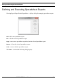
Defining and Executing Spreadsheet Exports........................ 190
SIMPROCESS User’s Manual
4
Organization of the SIMPROCESS
Documentation Set
The SIMPROCESS documentation set consists of four manuals:
•
•
•
•
Getting Started With SIMPROCESS
SIMPROCESS User’s Manual
SIMPROCESS Metadata Manual
SIMPROCESS OrgModel Manual
All of the manuals can be opened directly from the Help/SIMPROCESS Manuals menu. Also,
each manual includes this section which provides links to the chapters in every manual. Press
the Control key when clicking any link to open the linked file in a new window. For Windows
systems, in order for links between manuals to work properly, Adobe Acrobat or Acrobat
Reader must be used to view the manuals.
Getting Started
The Getting Started With SIMPROCESS manual is a must for first time SIMPROCESS users.
This manual can also be used for evaluation purposes. The chapters are
•
•
Business Process Modeling With SIMPROCESS
Installation
6
•
•
•
Building Your First Model With SIMPROCESS
Evaluating Alternatives With SIMPROCESS
Demonstration and Reference Models
User’s Manual
The User’s Manual is divided into four parts with each part being a separate file. Part A is an excellent
reference for beginners and casual users. This part contains detailed documentation of the basic and
intermediate functions of SIMPROCESS. The chapters are
•
•
•
•
•
•
•
•
Process Modeling and Analysis with SIMPROCESS
SIMPROCESS Basics
Statistical Modeling Constructs
Activity Modeling Constructs
Resource Modeling Constructs
Graphical Modeling Constructs
Activity-Based Costing
Statistical Output Reports
Part B is a reference intended for advanced users of SIMPROCESS. This part contains detailed
documentation of the programming and library management functions in SIMPROCESS Professional
Edition. The chapters are
•
•
•
•
Reusable Templates and Libraries
Customizing a Model with Attributes and Expressions
More Advanced Model Building
Exporting Results
Part C describes the integrated tools included with SIMPROCESS Professional. The chapters are
•
•
•
•
•
•
•
•
Advanced Data Analysis
SIMPROCESS Database
Experiment Manager
OptQuest for SIMPROCESS
SIMPROCESS Dashboards
Model Bundles
Custom Reports
Scenarios
7
The Appendices are
•
•
•
•
•
•
•
•
•
•
•
Importing Version 2.2.1 Models
Activity Summary Table
SIMPROCESS File Structure
Statistical Distributions
Statistical Tools Glossary
SIMPROCESS System Attributes and Methods
External Event Files
Simulation Results File
UML Interfaces
Running Models Without GUI
SIMPROCESS and External Java Classes
Metadata Manual
The Metadata Manual describes how to build and edit SIMPROCESS metamodels, assign metamodels
to a SIMPROCESS model, and enter metadata in a SIMPROCESS model. The chapters are
•
•
•
•
•
SIMPROCESS Metadata
SIMPROCESS Metamodel Editor
Assigning Metamodels
Entering Metadata
BPEL Metadata
OrgModel Manual
The OrgModel Manual describes how to build and edit SIMPROCESS Organization and Resource
Models (OrgModels) and assign OrgModels to a SIMPROCESS model. The chapters are
•
•
•
•
SIMPROCESS Organization and Resource Models
SIMPROCESS OrgModel Editor
Assigning OrgModels
Using OrgModels with SIMPROCESS
8
CHAPTER 1
Reusable Templates and Libraries
One of the most powerful features of SIMPROCESS is the reusable Template. A Template is an
Activity, hierarchical Process, Resource, Resource Downtime, or Resource Shift that is defined and
reused over and over. A Library is a collection of templates that can be saved and loaded during a
modeling session. SIMPROCESS provides a standard set of templates, such as Activities, Processes,
Resources, Resource Downtimes, and Resource Shifts. Templates provide the ability to set default
parameters for SIMPROCESS-provided items. For example, specialized Resources such as Tellers,
Loan Officers, Branch Managers can be defined in the Resource Library for Business Process Modeling
in a financial services business. A Library could also contain templates that may represent competing
models of the Business Processes that are being compared.
Many different Templates can be created and loaded into the system when they are needed. Customized
Processes/Activities can be added to the Library Toolbar (for easy reuse) and/or added to the Create
pull-down menu.
SIMPROCESS User’s Manual
8
Library Concepts
Library Concepts
The SIMPROCESS Template and Library feature supports the reuse and organization of the various
constructs used in building models.
The development of specialized objects organized into Libraries is encouraged. Over time, the Libraries
of objects will grow. With a large set of Libraries of reusable model building blocks, new models can
be built faster. For example, a set of Processes (Warehouse, Manufacture, Transport) and Resources
(Trucks, People, etc.) relevant to the Distribution domain can be created and saved to a Library named
Distribution. These can then be used to quickly build distribution models.
Libraries built can be saved and loaded during the modeling session as they are needed. The import
and export features enable the sharing of Libraries with colleagues and increases the building blocks
available for model construction.
In addition to providing a repository for storing categories of modeling constructs, the Library
Management facilities can be used to customize defaults for model elements that are built into
SIMPROCESS (statistical distributions, Activity parameters, etc.). Processes and Activities that are
used frequently can be kept on the Library Toolbar for quick access. Processes and Activities that are
used less frequently can be accessed through the Create pull-down menu.
See “File Menu” for information on using a model’s Group ID with templates.
In summary, Libraries:
•
•
•
•
•
Are repositories for model building constructs created by the user
Facilitate reuse of Processes, Activities, Resources, and Resource Downtimes
Allow placement of Processes and Activities on the Library Toolbar and the Create menu
Allow the grouping of Processes and Activities in user-defined templates
Facilitate importing and exporting of customized model elements for use in other models or
by colleagues.
SIMPROCESS User’s Manual
9
Defining and Editing Templates
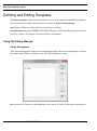
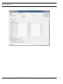
Defining and Editing Templates
The Define/Templates pull-down menu provides access to various options for manipulating templates.
The two functions available under this pull down menu are Add and Library Manager.
Add
displays a dialog for adding a Process or Activity to a Library.
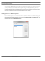
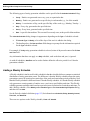
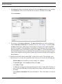
Library Manager brings up the SIMPROCESS Library Manager. The Library Manager is used to create,
load, save, remove, edit, import, and export Libraries of templates
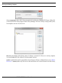
Using The Library Manager
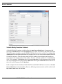
Library Management
The Library Manager is the primary tool for managing templates. Before creating templates, a Library
should be created. When no Libraries exist, the Library Manager is empty.
New
creates a new Library in which templates can be stored. A dialog for entering a name appears.
SIMPROCESS User’s Manual
10
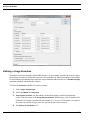
Defining and Editing Templates
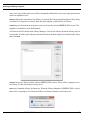
Select Load at Start to have this Library automatically loaded when SIMPROCESS starts. When OK
is selected, the new Library appears in the Library Manager. This new Library is empty at this point,
but templates can now be stored in it.
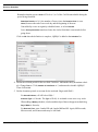
Edit allows the editing of the Library name if a Library is selected. If a Process or Activity template
is selected, Edit allows the editing of certain template options.
Update is enabled if a model is open and the selected item in a Library is a Master Process (see “Master
Processes”). Update updates any Processes in the model that were created from the selected Library
SIMPROCESS User’s Manual
11
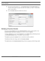
Defining and Editing Templates
item. Also, if any of these Processes still are designated as Master Processes, any copies pasted in the
model are updated as well.
Remove deletes the selected item. If a Library is selected, the Library and all templates in the Library
are deleted. If a template is selected, then only that template is deleted from its Library.
brings a Library that has been previously saved into the current SIMPROCESS session. The
templates can then be used to build models.
Load
All Libraries will be shown in the Library Manager. A dot by the Library means the Library has not
been loaded. A folder by the Library means that it has been loaded. Simply select the desired Library
and click Load.
Unload removes a Library from the current SIMPROCESS session. There will be a prompt to save
the Library if it has not been previously saved.
Save saves a template Library for future use. When the Library Manager or SIMPROCESS is closed,
there will be a prompt to save Libraries if there are Libraries that have not been saved.
SIMPROCESS User’s Manual
12
Defining and Editing Templates
Import
imports a Library file that was exported by another SIMPROCESS user.
Export
exports a Library file that another SIMPROCESS user can import.
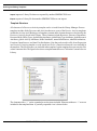
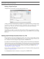
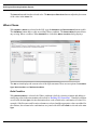
Template Structure
All elements of a Process or Activity template can be viewed from the Library Manager. Process
templates include all the Processes and Activities that were a part of the Process. Activity templates
include the Activity itself. Both types of templates contain other elements that were referenced by the
Process or Activity placed in the Library. These elements include Resources, Resource Downtimes,
Resource Shifts, Entity Types, global Entity Attributes, global Entity Type Attributes, global Resource
Attributes, global Activity Attributes, Model Attributes, named distributions, tabular distributions,
Functions, Input Sources, and Auto Fits distributions. Note that code stored in a file for an Expression
in a Process or Activity template or code stored in a file for a Function referenced is not included in
the template. The file references are included in the template, but the template does not carry the files
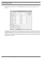
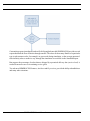
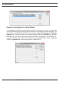
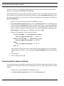
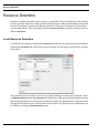
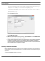
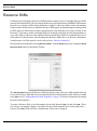
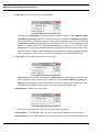
or their content with it. The figure below shows a template named Process Calls in the Customer Service
Library.
The elements with a “+” can be expanded to see the items included. Elements without a “+” were not
included in the templated item. A partially expanded view is shown below.
SIMPROCESS User’s Manual
13
Defining and Editing Templates
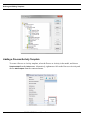
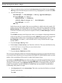
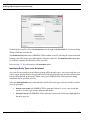
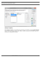
Adding a Process/Activity Template
To create a Process or Activity template, select the Process or Activity in the model, and choose
Templates/Add from the Define menu. Alternatively, right mouse click on the Process or Activity and
choose Add Template from the contextual menu.
SIMPROCESS User’s Manual
14
Defining and Editing Templates
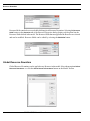
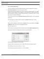
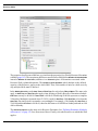
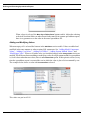
This brings up a dialog where the template options can be set.
Label
is the name of the template that will be stored in the selected Library.
Layout Icon
is the icon that will display when the template is used in a model.
Library Toolbar Parameters determine the Library Toolbar settings. If On is checked, the template will
appear on the Library Toolbar. The Library Toolbar is on the right side of the screen. If Custom Toolbar
Icon is selected the Toolbar Icon list is active.
The icon for the template on the Library Toolbar is selected from the Toolbar Icon list. The Toolbar Label
is the tool tip that will appear when the mouse is over the icon.
Menu Parameters determine the menu placement of the template. If On is selected, the template will
appear on one of the Create sub-menus with the name from the Label field. Menu Owner sets the submenu for the template. One of the current sub-menus can be used or a custom menu name can be entered.
As shown above, On can be selected for both Library Toolbar Parameters and Menu Parameters. However,
must be selected for at least one of the two.
On
The Library that this template should be added to is selected from the Add to Library list. If no Library
has been created, then the template will be added to a Library named Default (which can be renamed).
Adding Resource Templates
Resource templates are created from the Resource list. The Resource list displays all the resources
SIMPROCESS User’s Manual
15
Defining and Editing Templates
defined in the model. It is accessed from Resources on the Define menu. The Resource list has an Add
Template button.
Select the Resource and click the Add Template button. This brings up the properties of the template.
The template properties are simply the Resource properties with the Add to Library option added. As
with the other template types, if there has not been a Library defined, the Resource template will go
SIMPROCESS User’s Manual
16
Defining and Editing Templates
into the Default Library. Resource templates display in the Type combo box on the Resource list dialog
as long as the Library in which the Resource templates reside is loaded.
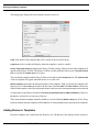
Adding Resource Downtime Templates
Resource Downtime templates are created from the Resource Downtime list. The Resource Downtime
list displays all the resource downtimes defined in the model. It is accessed from Resource Downtimes
on the Define menu. The Resource Downtime list has an Add Template button.
Select the Service Downtime and click the Add Template button. This brings up the properties of the
template.
The template properties are the Resource Downtime properties with the Resource assignments
SIMPROCESS User’s Manual
17
Defining and Editing Templates
removed and the Add to Library option added. As with the other template types, if there has not been
a Library defined, the Resource Downtime template will go into the Default Library. Resource
Downtime templates display in the Type combo box on the Resource Downtime list dialog as long as
the Library in which the Resource Downtime templates reside is loaded.
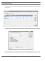
Adding Resource Shift Templates
Resource Shift templates are created from the Resource Shift list. The Resource Shift list displays all
the resource shifts defined in the model. It is accessed from Resource Shifts on the Define menu. The
Resource Shift list has an Add Template button.
SIMPROCESS User’s Manual
18
Defining and Editing Templates
Select the Resource Shift and click the Add Template button. This brings up the properties of the
template.
The template properties are the Resource Shift properties with the Resource assignments removed and
the Add to Library option added. As with the other template types, if there has not been a Library defined,
the Resource Shift template will go into the Default Library. Resource Shift templates display in the
Type combo box on the Resource Shift list dialog as long as the Library in which the Resource Shift
templates reside is loaded.
SIMPROCESS User’s Manual
19
Editing Templates
Editing Templates
Templates cannot be edited directly from the Library Manager. However, template Library parameters
can be edited from the Library Manager.
Editing Templates
Templates can only be edited within a model. Thus, the way to change a template is to open the original
model from which the template was created, make the necessary changes to the original Process or
Activity, then add the changed item to the Library. If it is added with the same name, it replaces the
original. If the item changed is a Master Process, the Update button can be used to update models that
use the template. Alternatively, the template can be added to a model, modified, and then added to
the Library. In this instance, the original template is not replaced even if the same name is used.
Therefore, Update will not change any Processes created from the original template.
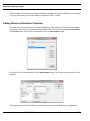
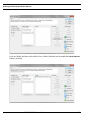
Editing Library Parameters
To change the Library options for a template, select the template in the Library Manager and click
the Edit button. This will bring up the same properties dialog that appeared when the template was
added to its Library. The only difference is that the Library for the template cannot be changed.
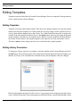
Below are the template properties for Sales Process. Any property can be changed except the Library
owner. That field is missing. To place the template in a different Library, it must be added to that Library.
SIMPROCESS User’s Manual
20
Editing Templates
SIMPROCESS User’s Manual
21
Advantage of Templates Over Copy/Paste
Advantage of Templates Over Copy/Paste
Portions of models can be copied from one model and pasted into another model. However, the copy
action only copies the Activity/Connector structure. References to Entities, Resources, Resource
Downtimes, user defined distributions, Input Sources, Functions, or Attributes within the Activities
are not carried because those items may or may not exist in the model in which the paste occurs. This
means all those references must be redefined in the new model. When this occurs, a dialog will appear
after the paste that lists the items that have invalid references. Those items can be edited from the list.
Note that, by definition, Input Sources refer to files that are external to SIMPROCESS. External files
are not included in templates. Thus, additional files must be included separately, and any Input Sources
created by adding a templated item to a model may need to be modified to ensure the locations of the
external sources are correct in the Input Source definitions.
Templates also allow portions of one model to be used in another model. However, since templates
carry references to the Entities, Resources, and Attributes used, those items remain referenced in the
Activities. Those references do not have to be redefined in the new model.
SIMPROCESS User’s Manual
22
CHAPTER 2
Customizing a Model with Attributes and
Expressions
SIMPROCESS provides a wide range of predefined model elements and statistical options, but every
business Process is unique in some way. There will be times when flexibility is needed to model complex
situations, and the built-in functions of SIMPROCESS may be inadequate. In those cases, Attributes
and Expressions can be defined.
For example, a typical SIMPROCESS model for an appliance manufacturer’s distribution Process
might include a batch Activity where customer orders are collected for shipment. Products may be
shipped on a predetermined schedule, or when the total number of pending orders reaches a certain
number. The SIMPROCESS Batch Activity readily handles these scenarios with the Quantity to Batch
and Release Threshold options.
But suppose the dispatching of a shipment depends on the total weight of the appliances that have been
accumulated. How is this situation modeled?
SIMPROCESS User’s Manual
23
Customizing reports is another area where flexibility might be needed. SIMPROCESS provides several
reports that track the flow of Entities through a model. The values for how many Entities of a particular
type (each customer order, for example) are processed during simulation, or the average amount of
time an Entity takes to make its way through the simulation are available in the Standard Report.
But suppose the percentage of orders that are shipped by a promised delivery date (service level) is
needed to measure success in attaining service goals.
Two advanced SIMPROCESS features, Attributes and Expressions, provide the ability to handle these
and many other situations.
SIMPROCESS User’s Manual
24
Introduction to Attributes and Expressions
Introduction to Attributes and Expressions
Attributes
Attributes are user-defined and built-in variables of model elements whose values can change during
the course of a simulation run. For example, for a Batch Process where Entity release depends on the
weight of the Entities received, an Attribute is the total weight of the items accumulated in the Batch
Activity.
To determine the percentage of orders processed within a specified period of time, Attributes need
to track the processing time for each order, the number of orders that meet the promised delivery date,
and the total number of orders processed.
Attributes may be used to:
•
•
•
Alter the behavior of a Process by changing the value of an Attribute during a simulation
Communicate information (such as Attribute values) between two Processes in a model
Store data collected during a simulation run.
There are two categories of SIMPROCESS Attributes: built-in System Attributes, which
SIMPROCESS automatically creates and updates, and User Defined Attributes, which the user creates.
For example, the number of Entities generated for each Entity type (e.g., number of orders) is
automatically tracked and stored in a built-in System Attribute named NumberCreated. To track
an Attribute such as weight, which SIMPROCESS does not know about, an Attribute called
applianceWeight could be created.
Some System Attributes can be modified by users. These are called “Get-Set” type System Attributes.
Generally, these are variables that control Process parameters such as the number of Entities to batch
or amount of time of the next delay. By modifying these System Attributes, the behavior of the
simulation can be affected.
System Attributes that cannot be changed include those that monitor statistics, such as the number of
Entities generated during the simulation. These are called “Get-Only” type System Attributes.
Information on the status of a simulation, such as which Activity is processing an Entity or what type
of Entity is being processed, is also available through “Get-Only” System Attributes.
See “SIMPROCESS System Attributes and Methods” for a complete list of System Attributes.
Expressions
Attributes are a powerful simulation feature when used in conjunction with SIMPROCESS
SIMPROCESS User’s Manual
25
Introduction to Attributes and Expressions
Expressions. Expressions are user-written statements that SIMPROCESS executes during a simulation
run. Expressions are defined at the point at which the Expression is to be evaluated; for example, at
the beginning of the simulation, or at the moment an Entity (e.g., a customer order) is received by an
Activity (e.g., order distribution).
In the case of the model where releasing of shipments depends on the total weight of orders such as
appliances, the following could be done:
1. Define an Attribute called applianceWeight and set its value whenever an applianceorder Entity is generated by SIMPROCESS. The value to assign applianceWeight would
be determined by checking the name of the Entity type (e.g., dishwasher-order, televisionorder). This information is available from the System Attribute Name.
2. When an Entity is received at the Batch Activity, the Entity’s applianceWeight value
would be added to the total weight of all orders waiting to be shipped (another User Attribute).
The total weight would then be checked. If it exceeds a certain value, the Batch Activity would
be forced to release a shipment.
One way to force a shipment to be released is to change the batch size to a value equal to the current
number of Entities in the Batch Activity. These values are available in System Attributes.
This chapter describes:
• Built-in System Attributes
• User-Defined Attributes
• How to write an Expression which uses User-Defined Attributes and System Attributes.
SIMPROCESS User’s Manual
26
Using Attributes in SIMPROCESS
Using Attributes in SIMPROCESS
This section contains a closer look at Attributes and how they can be used in SIMPROCESS. It starts
with a look at the System Attributes built into SIMPROCESS and then goes on to a detailed discussion
of User-Defined Attributes.
System Attributes
SIMPROCESS provides access to the state of a simulation through a set of built-in variables. These
System Attributes provide information such as:
• The type of Entity currently in an Activity
• The number of Entities of a particular type that have been generated thus far in the simulation
• The name of the Activity holding a particular Entity
• The type of Entity being generated by a Generate Activity.
A complete list of System Attributes is given in “SIMPROCESS System Attributes and Methods”.
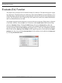
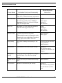
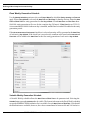
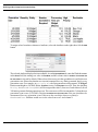
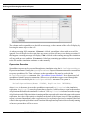
The table entries below show the Attributes accessible from Batch Activities:
Object
Name
Type
Get/
Set
Batch MaxBatchSize INTEGER Both
Activities MinBatchSize INTEGER Both
MaxWaitTime
REAL
Both
Description
Number of Entities to batch.
Number of Entities must be in a batch
before it can be released.
Time to wait before releasing an
undersized batch.
1. The MaxBatchSize Attribute is an integer value representing the maximum number of Entities
to batch at a Batch Activity. The current value of the Attribute can be retrieved and changed.
2. The MinBatchSize Attribute is an integer value containing the minimum number of Entities
a Batch Activity must hold before it can release a batched Entity.
3. The Attribute MaxWaitTime specifies the maximum amount of time to wait before releasing
the batched Entities that have met the Activity’s MinBatchSize. The value is a real number
(e.g., 1.0, 7.5, etc.) representing the time unit selected for the maximum wait time. The value
of this Attribute can be retrieved and changed.
SIMPROCESS User’s Manual
27
User Defined Attributes
User Defined Attributes
Customizing a model begins with defining Attributes. These Attributes can represent model element
Attributes that are not built into SIMPROCESS, such as Entity weight and size or skill level of a
Resource.
Attributes can be defined in association with:
•
•
•
•
Entity types or Entity instances
Processes or Activities
Resources
The Model itself.
How an Attribute is defined tells SIMPROCESS whether to create an instance of that Attribute for every
model element of the same type (e.g., Entities, Resources), or to just create the Attribute for a particular
type of model element (customer order Entities, truck Resources). In SIMPROCESS terminology,
Attributes are either globally-defined or locally-defined. Model Attributes are only globally-defined.
When an Attribute is defined globally, an instance of that Attribute is automatically created for each
model element of that class. For example, if the model contains Entities of different types of appliances
(refrigerators, televisions, toasters, etc.) and a weight value needs to be assigned to each Entity, a global
Entity Attribute could be defined (applianceWeight). SIMPROCESS creates an instance of that
Attribute for every Entity in the model, so every Entity has an appliance weight Attribute which can
be referenced.
The only Activity concerned with weight is the Activity where Entities are batched. In this case, it makes
sense to locally define an Attribute for that particular Activity. When it’s done this way no other Activity
will have a weight Attribute automatically created for it.
Note that Attributes for different model elements can have the same name. For example, a global
Attribute called applianceWeight could be defined for Resources. It can have a completely different
meaning and data type. Global and local Attributes for the same model element cannot have the same
name.
All attributes (global or local) are managed using a table similar to Entities and Resources. Changes
to global attribute definitions from the table cannot be canceled. Each table can be sorted by a particular
column by clicking the column header. Holding the Shift key while clicking the column header causes
the sort to be in reverse order.
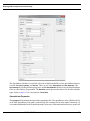
Creating a User Defined Attribute
Global Attributes can be defined from the SIMPROCESS menu or from the dialog of a model element.
SIMPROCESS User’s Manual
28
User Defined Attributes
Local Attributes can only be defined from the dialog of a model element.
Globally Defining an Attribute from the Menu
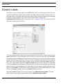
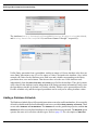
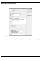
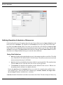
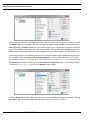
To globally define an Attribute from the SIMPROCESS menu select Global Attributes... from the Define
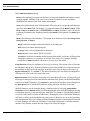
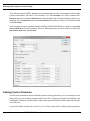
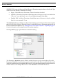
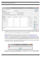
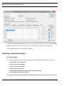
menu or click the Define Global Attributes button on the Model Toolbar. The following dialog appears:
The Global Attribute Definitions dialog is used to add a new Attribute or to change, copy, or delete existing
Attributes. There are five tabs: Entity, Entity Type, Resource, Activity, and Model. Each tab represents
model elements for which global Attributes can be defined. Note that the Entity tab defines Attributes
for each Entity instance created by the simulation. The originating Entity Type for the Entity instance
is not considered. So every Entity instance created by the simulation will have an instance of each
Attribute listed on the Entity tab. Attributes defined from the Entity Type tab are assigned to each Entity
Type. That is, for all Attributes listed on the Entity Type tab, there is one of each Attribute created for
each Entity Type that all Entity instances originating from that type can reference. Each tab shows
the names of all Attributes of that type previously defined. If no Attributes have been defined, the list
in each tab will be empty and the Edit, Copy, and Remove buttons will be inactive. The Undo button
activates when an Attribute is removed. Select the Entity tab and click on Add to create a new Attribute.
SIMPROCESS User’s Manual
29
User Defined Attributes
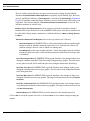
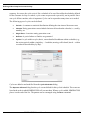
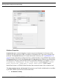
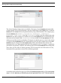
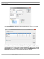
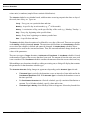
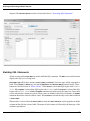
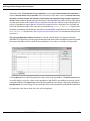
In the Attribute Properties dialog:
Name can be anything (except as noted below), as long as the name has not been previously
used for another Attribute of the same class of model element. For new Attributes,
SIMPROCESS initializes the field with a default name.
Value is the default initial value of this Attribute. The value must correspond to the data type
specified in the Mode field. For instance, 1.0 cannot be entered if the Mode is Integer. If the
Mode is Object, the Default value is UNDEFINED. An Object Attribute’s value can only be
set during a simulation run. Anything entered in the Default field is ignored. (See Mode types
below.)
Mode is the data type of the Attribute. Click on the arrow button to select either Integer, Real,
String, Boolean,
Integer
Real
or Object:
values are numbers without fractional or decimal parts.
values can contain fractional parts.
A String is any series of alphanumeric characters.
Boolean
values can be either TRUE or FALSE.
An Object is a reference to another model element in the model, a reference for Expression
Language constructs, or a reference to external Java classes. For example, during a
simulation an Object Attribute can point to an Activity in the model.
Array Dimension allows for Attributes to be set up as an array. The default value of 0 means
the Attribute is not an array. If an array dimension is provided and the user wishes to reference
the Attribute in the Expression language, it must be done using an integer subscript (e.g.,
myattribute[2]:= value;). The subscripted arrays are zero-based, meaning that a
subscript of 0 refers to the first item in the array.
Model Parameter, when checked, means that every time the model is run, a dialog will open
allowing new initial values to be entered for the Attribute. Only global, user-defined Attributes
can be set as Model Parameters. If a Comment is entered for the Attribute, this will appear in
the Description field of the Model Parameters dialog when the Attribute is selected.
Model Parameters can be changed during a simulation run by selecting Change Model
Parameters from the Simulate menu. Note that changing the value of Model Parameters during
a simulation run may or may not affect the simulation. For instance, if the Model Parameter
is used to set the number of units of a Resource, changing the value of the Model Parameter
will have no affect on the simulation since the units of a Resource are set at the beginning
of a simulation run. However, changes to Model Parameters used to control entity flow or used
for time durations will affect the simulation. If the Model Parameter is an Entity instance
attribute, only Entities created after the change will reflect the change.
SIMPROCESS User’s Manual
30
User Defined Attributes
There is another option that does not appear on the properties dialog for global Entity
Attributes. Do Not Reset Before Each Replication is a property of global Entity Type, Resource,
Activity, and Model Attributes. If Reset System is selected on the Run Settings (Simulation
Period), all Attributes (other than Entity Attributes) are reset to their initial value before each
replication. This does not happen if Do Not Reset Before Each Replication is selected. The
Attribute maintains its current value.
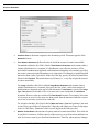
and Report Requests refer to statistics collected for Attributes during a
simulation run. These statistics are used in SIMPROCESS reports. Note that no statistics can
be collected for Entity instance Attributes or Attributes that have a Mode of String, Boolean,
or Object.
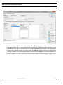
Statistics Types
Observation Based and Time-Weighted
refer to the way statistics are collected:
Observation Based tells SIMPROCESS to collect statistical data without considering the
amount of time an Attribute maintains a particular level. Each time the value of an
Attribute changes, the new value is added to a running total.
Time-Weighted provides time-weighted statistics. That is, the length of time an Attribute
remains at a particular value is factored into the statistical data when the average value
is calculated.
Real-Time Histogram Plot tells SIMPROCESS to plot the Attribute value changes as they occur
during the simulation run (Real Time Plot) using a Histogram-type graphic. The plots can be
saved, printed, resized, and re-read from prior saves using the menu on the Plot dialog.
Real-Time Trace Plot tells SIMPROCESS to plot the Attribute value changes as they occur
during the simulation run to a trace type graphic. The trace plots can be manipulated similar
to the Histogram Plots.
tells SIMPROCESS to plot the Attribute value changes as they occur
during the simulation to meter type graphic. The range for the meter must be set with Set Plot
Properties.
Real-Time Meter Plot
Real-Time Thermometer Plot tells SIMPROCESS to plot the Attribute value changes as they
occur during the simulation to thermometer type graphic. The range for the meter must be set
with Set Plot Properties.
Standard Report tells SIMPROCESS to write the statistics to the standard report file.
Click on OK to accept the options selected, or click on Cancel to exit without setting/resetting any
options.
SIMPROCESS User’s Manual
31
User Defined Attributes
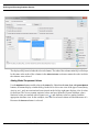
An existing user Attribute can be copied by selecting the Attribute in the table and then clicking on
the Copy button. The Global Attribute Properties dialog is displayed with the options and defaults set
to the values of the copied Attribute.
To remove an existing user Attribute, select the Attribute from the table, and then click on the Remove
button. The Undo button will restore an Attribute definition that was removed.
The Local button is on every tab except the Model tab (Model Attributes are only global). Selecting
Local brings up a dialog that displays all model elements of the same type that have local Attributes.
For example, the Local button on the Activity tab shows all Activities that have local Attributes defined.
Selecting an item on the left displays the local Attributes for that item on the right. An item on the
left can be edited by double clicking or by selecting the Edit... button. Note that from this dialog local
Attributes cannot be defined for items that do not already have local Attributes.
Click on Close when finished defining or modifying global Attributes.
Globally Defining Attributes from Dialogs
All global Attributes (other than Model Attributes) can also be accessed from the properties dialog
of the appropriate model element (Entity, Resource, or Activity). For example, assume a model has
three Entities defined (refrigerator-order, television-order, and toaster-order). Selecting Entities... from
SIMPROCESS User’s Manual
32
User Defined Attributes
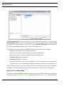
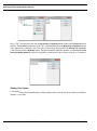
the Define menu, brings up the list of defined Entities.
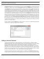
Editing the refrigerator-order brings up the properties dialog. The image below shows the Entity
tab selected.
Attributes
There are no local Entity Attributes defined for this Entity. The Global button brings up the Global
Attribute Definitions dialog with the appropriate tab active. Since the Entity Attribute tab is selected
on the Entity properties dialog, the Entity tab will be active on the Global Attribute Definitions dialog.
Note that the Local button is missing since the Global Attribute Definitions dialog was opened from
the properties dialog of a model element.
SIMPROCESS User’s Manual
33
User Defined Attributes
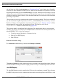
Defining a Local Attribute for a Model Element
A local Attribute is defined for a single model element (Entity, Resource, or Activity). Local Attributes
are defined from the properties dialog of the model element. Note that Entity instance and Entity Type
local Attributes are both defined from the Entity properties dialog (Entity Attributes and Entity Type
Attributes tabs). The Resource and Activity properties dialog each have an Attributes tab. Attributes
defined locally exist only for the model element in which they were defined. Local Attributes are
managed in the same manner as the Global Attributes by using the Add..., Edit..., Copy..., and Remove
buttons. The Attributes tab for Resource properties is shown below.
SIMPROCESS User’s Manual
34
Assign Activity
Assign Activity
The Assign Activity can be used to assign values to globally defined Attributes and local Entity instance
and Entity Type Attributes. The Assign can also change the priority of an Entity.
Changing an Attribute Value with the Assign Activity
The Set Attribute list box of the Assign Activity is used to change the value of any global Attribute
(except globally-defined Resource Attributes) and local Entity instance and Entity Type Attributes.
Once an Attribute has been selected, clicking on the Add button will open up the Assign Attribute
Properties dialog.
The combo box in the Set Attributes field contains the names of all the Attributes that the Assign Activity
can access. Selecting an Attribute from the pull down list and then clicking on the Add button will open
the Attribute Assignment dialog where the Attribute value is specified. Likewise, by selecting an Attribute
from the left side of the Set Attributes list and clicking on the Remove or Edit buttons an Attribute
assignment can be removed or changed.
The Operation field contains the operators that can be used to change the value of the selected
Attribute. The supported operators are; =, +, -, *, and / (equals, addition, subtraction,
multiplication, and division).
SIMPROCESS User’s Manual
35
Assign Activity
The Value field contains the value to be used with the Operation. This can take the form of
a constant, a Statistical Distribution, a User-defined Function, or an Evaluate (Evl) Function.
User-defined Functions can be found on page 83 of this chapter. The Evaluate Function is
covered on page 54.
Each time an Entity enters the Assign Activity, the Set Attribute commands are performed.
Important: If the Attribute selected for assignment is a local Entity or Entity Type Attribute,
a run time error will occur if an Entity enters the Activity that does not have the selected
Attribute defined.
SIMPROCESS User’s Manual
36
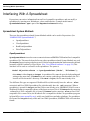
Variable Resource Usage
Variable Resource Usage
The most flexible way to vary Resource usage is through the GetResource and FreeResource
expression statements (see “Getting and Freeing Resources Using Expressions” on page 71). However,
Resource usage can also be varied by parameterizing the Resource requests on the Resources tab of
Activity property dialogs. The number of units, the Resource requested, or both can be parameterized.
Varying Resource Units
User-defined Attributes can be used to request units of Resources. Using an Attribute allows the units
of Resource required by each Entity to vary. For instance, in the example from Chapter 5 of Part A
(Adding Resource Requirements to Activities) an Entity needed one unit of the Service Rep Resource
for that Activity.
Thus, every Entity will get one and only one unit of the Resource. However, there may be instances
where the amount of Resources needed would be different for each Entity. This is true many times
when using consumable Resources (such as fuel). Any type of Attribute may be used to set these levels
(Entity, Entity.Type, Resource, Activity, or Model). When Attributes are used, they must be provided
in the Evl distribution function such as “Evl(Model.myattribute).” The Evl function gives added
flexibility since mathematical functions can be used with the Attributes. “Evl(Model.myattribute +
(Entity.myEntityattribute * SQRT(Activity.myActivityattribute))” is an example.
In addition to Attributes, any statistical distribution may be used. Use Edit to modify the existing
requirement definition and then enter the Attribute that will have the unit information. The Attribute
SIMPROCESS User’s Manual
37
Variable Resource Usage
must be a real or integer type Attribute.
During the simulation run, if the units of Resource requested is larger than the Resource capacity, the
Entity will not proceed since there will never be more units available than capacity. This will not occur
when using consumable Resources. If the Resource is consumable, the Entity will continue when more
Resource units are available. Also, if a fractional number of units is requested and fractional usage
was not selected for the Resource, an error will occur.
Varying Resources
There may also be times when it is useful to vary the Resources assigned to an Activity. While the
units requested can change from Entity to Entity within a simulation run, the actual Resources assigned
can only change from run to run. Resources can be varied on the Resources tab by using Model
Attributes. Under the Requirements list are a Model Attributes label, a combo box, and an Add Model
Parameter button. These are normally disabled but are enabled when the model contains Model
Attributes of type String that are also designated as Model Parameters. (See “Creating a User Defined
Attribute” on page 28 for information on creating Model Attributes.)
SIMPROCESS User’s Manual
38
Variable Resource Usage
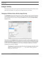
To illustrate, consider the model created from the tutorial in the SIMPROCESS Getting Started Manual,
As-Is.spm (located in the models/Demos directory). There are two Resources defined in the
model, Sales Rep and Service Rep. The Sales Rep Resource is used for the Sales Delay Activity, and
the Service Rep Resource is used for the Customer Service Delay Activity. The tutorial also has an
alternative. Instead of two different Resources for Sales and Customer Service, the alternative uses
one Resource called Customer Rep. To run the alternative a Customer Rep resource must be defined
(as seen in To-Be.spm in the models/Demos directory). Also, either the model has to be edited
to remove the assignment of Service Rep and include the assignment of Customer Rep, or a new
alternative for Process Calls must be created that uses Customer Rep instead of Service Rep and Sales
Rep. (See “Alternative Sub-Processes” for information on Process alternatives.) Another way to run
the two alternatives is to vary the Resource requests by creating Model Attributes for each Resource.
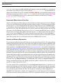
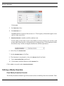
For example, see the Attribute definition below. The Attribute is named SalesRepType. The Mode
is String, and the default Value is "Sales Rep", which is the name of one of the Resources. Note that
Model Parameter is checked.
Another Model Attribute is created called ServiceRepType with a default value of Service Rep. As
shown above in “Varying Resource Units” on page 37, the Service Rep Resource was specified as the
Resource needed for the Customer Service Activity. Instead of changing the model or creating a Process
alternative, a Model Attribute can be used to specify the Resource request. In the image below the Model
Attributes section of the Resource tab is enabled. This is because the two Model Attributes described
above (SalesRepType and ServiceRepType) were added to the model. Both have a Mode of String
and each was designated as a Model Parameter.
SIMPROCESS User’s Manual
39
Variable Resource Usage
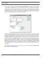
To add a Model Attribute to the Requirements list, select the desired Attribute from the combo box
then click Add Model Attribute.
Now the Activity has one Resource request represented by the Model Attribute SalesRepType. Note
that the icon in front of the Attribute name indicates that this is a Model Attribute instead of a Resource.
When the simulation is run, the value of SalesRepType is taken to be the Resource requested. Since
SalesRepType is a Model Parameter, the value can be changed before the start of the simulation (see
SIMPROCESS User’s Manual
40
Variable Resource Usage
“Running a Simulation with Model Parameters”). Thus, the value of SalesRepType must be the name
of a Resource defined in the model or a run time error will occur. The units can be varied in the same
way as a Resource in the Requirements list by clicking the Edit button. The Remove button removes
the Attribute from the Requirements list and places the Attribute back in the combo box.
Note, the same Model Attributes that are available to specify Resource usage are also available in Free
Resource Activities to specify which Resource to release. The Model Attributes are listed with the
Resources but include "Model." along with the Attribute name. See “Free Resource Activity” for more
information on using the Free Resource Activity.
SIMPROCESS User’s Manual
41
Writing Expressions
Writing Expressions
The previous section discussed how to define user Attributes. This section discusses how to use them.
For Attributes to be useful, they must be able to be accessed and changed during a simulation run.
SIMPROCESS provides opportunities to do this at many points during a simulation. The instructions
written to process Attributes and SIMPROCESS model elements are called Expressions.
An Expression is a user-defined routine that runs within the larger SIMPROCESS program. In effect,
SIMPROCESS checks at various points during a simulation run to see if there are any special
instructions for it. If so, it runs the code. Expressions accomplish simulation and modeling requirements
for which standard SIMPROCESS processing does not support.
The SIMPROCESS Expression language is introduced first, then how Expressions are implemented
is explained.
SIMPROCESS Expression Language Basics
The SIMPROCESS Expression language contains the basic features of any programming language.
Complex Expressions can be written in this language.
In the definitions that follow, the word expression with a lower case “e” refers to a mathematical
expression. Expression with a capital “E” refers to the SIMPROCESS Expressions feature.
Types
SIMPROCESS supports a limited set of data types. The supported types are as follows:
• BOOLEAN
A variable that contains the binary values of TRUE or FALSE
• REAL
A variable that contains a real number
• INTEGER
A variable that contains an integer number
• STRING
A variable that contains an array of characters
Types are specified in either one of two ways: by declaring a variable local to the Expression such
as the variables myReal and myString:
SIMPROCESS User’s Manual
42
Writing Expressions
myReal : REAL;
myString : STRING;
or by selecting the Attribute type from the Attribute definition dialogs. The Attribute definition dialogs
support the same types that can be declared locally in the Expression. However, the data type of Object
is not supported in the Expressions. ANYOBJ is used instead of Object.
Operators
•
Assignment Operator
The assignment operator is used to assign a value to an Attribute:
:=
For example:
x := 15;
assignWeight := 1000;
The colon (:) preceding the equal sign (=) is required. An error will occur if it is omitted.
String values can be concatenated using the + operator:
For example:
mystring1:= "hello ";
mystring2:= "dolly";
mystring3:= mystring1 + mystring2;
The string mystring3 now contains the value “hello dolly”. String concatenation can also
be used on functions that return string values such as the SUBSTR function.
For example:
mystring1:= SUBSTR(1,5,mystring3) + " dude";
The variable mystring1 will now contain “hello dude”.
•
Compare Operator
An equal sign without a preceding colon is used when comparing two values. Thus, the
statement beginning:
IF assignWeight = 1000...
SIMPROCESS User’s Manual
43
Writing Expressions
compares the value of Attribute assignWeight to the number 1000.
•
Arithmetic Operators used in the SIMPROCESS Expression language are + (addition), (subtraction), * (multiplication), / (division), DIV (integer division), and MOD (modulus).
•
•
Relational Operators include =, <> (not equal), <, <=, >, >=.
Logical Operators are AND, OR, and NOT. Logical operators may only be used with
expressions that return a Boolean value. For example
IF x < 10.0 AND y >= 20.0
Note that parentheses must be used with the NOT operator if NOT is modifying any expression.
IF NOT (z = "End")
The above example could also be written as
IF z <> "End"
Literals
•
A string of printable characters on a single line is enclosed in quotation marks:
"The plain in Spain looks lovely in the rain.";
•
A boolean literal is entered as uppercase TRUE or FALSE:
myBool := TRUE;
•
An integer literal is entered as a whole number:
myInteger := 67;
•
A real literal is entered as a whole number plus a decimal, fraction, or whole number plus
a fraction:
myReal1 := 67.;
myReal2 := 67.133;
myReal3 := 0.345;
Type Checking
•
The use of variables (both those defined locally in the Expression and those defined as
Attributes) in Expressions will be checked for correct type on assignment statements. For
example, the following code will produce a type mismatch by the Expression interpreter.
myReal : REAL;
myString : STRING;
myString := "Hello Dolly";
myReal := myReal + myString;
SIMPROCESS User’s Manual
44
Writing Expressions
System Methods
•
System methods are commands which result in a system action or return a value from the
underlying system. One commonly-used function is SimTime, which returns a Real number
containing the current simulation time.
•
For a list of System Methods available in SIMPROCESS, refer to “SIMPROCESS System
Methods”.
Expression Language Statements
•
IF condition
{ELSIF condition}
{ELSE condition}
END IF;
•
WHILE condition
END WHILE;
•
FOR expression TO|DOWN TO expression [BY expression]
END FOR;
•
•
•
RETURN (possible return value)
EXIT (with WHILE or FOR loops)
OUTPUT
SIMPROCESS Expression language syntax:
1. The SIMPROCESS Expression language is case sensitive. An Attribute named
Applianceweight is not the same Attribute as the Attribute referred to as
applianceWeight.
2. All built-in language elements are in capital letters (IF, END,WHILE, etc.).
3. Each Expression language statement ends with a semicolon (;). The exceptions to this are
lines that begin with IF, ELSIF, ELSE, WHILE, and FOR.
4. Comments can be included in Expressions by enclosing them in curly brackets ({ }). For
example:
{This is a comment}
SIMPROCESS User’s Manual
45
Writing Expressions
Do not end a comment line with a semicolon.
5. Basic conditional logic has the form:
IF a < b
x := c;
ELSIF a < c
x := d;
END IF;
For example:
IF batchweight > 2000
MaxBatchSize := 100;
batchWeight := 0;
ELSIF batchweight > 1800
MaxBatchSize := 110;
END IF;
Messages can be displayed in the SIMPROCESS Expression Output Dialog with the OUTPUT
statement. This is useful for tracking the value of Attributes as a simulation proceeds. The OUTPUT
statement has the form:
OUTPUT(expression);
For example:
OUTPUT("Just assigned a weight to Entity");
OUTPUT("Current batch weight ",
batchWeight);
In the second example, the value of Attribute batchWeight is displayed following the text
"Current batch weight ". The literal string and Attribute name are separated by a comma so the
actual batchWeight value will appear next to the string.
SIMPROCESS User’s Manual
46
Writing Expressions
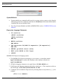
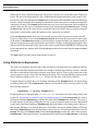
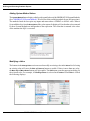
Expression Editor
Editing any Expression activation event brings up the Expression Editor, shown below. On the right
is the text area for entering the Expression. The dialog contains two menus: Edit and Define.
The Edit menu includes the traditional Undo, Redo, Cut, Copy, Paste and Select All items. It also includes
Find..., Replace... and Go To... items, any of which display a dialog containing Find, Replace and Go To
Line tabs. The Find and Replace features include matching case, whole word searching, search up/down
direction selection, and a Replace All command. The Go To Line tab allows movement directly to any
given line number of the expression text, which can be useful when a validation error message includes
a line number. Entering a very large number goes to the last line; entering zero or a negative value
goes to the first line; entering a non-numeric value causes an error message to be displayed. Note that
the current position of the cursor is displayed in the lower right corner of the dialog, just to the right
of the Save button. The first number is the line number, and the second number is the position within
the line. The last two items on the Edit menu are Expression Assistant and Validate Attributes (both
described below). Expression Assistant turns the SIMPROCESS Expression Assistant on or off. When
Validate Attributes is selected, global Attributes in the Expression are checked to determine if they have
been defined in the model. The status of both will persist across SIMPROCESS sessions.
The Define menu is used to create, delete, or modify global Attributes. The menu items are Entity
Attributes..., Entity Type Attributes..., Resource Attributes..., Activity Attributes..., and Model Attributes....
Selecting an item displays the same Global Attribute Definitions dialog as the Define/Global Attributes
menu item with the appropriate tab selected (see page 29). Once the dialog is displayed any tab can
be selected. When the dialog is closed, the User Defined Attributes tab (described below) is updated
to reflect any changes. Note that changes to global Attribute definitions are not reflected in the
Expression text.
The Validate button below the text area checks the syntax of the Expression without closing the editor.
The Done button checks the syntax of the Expression and, if there are no errors, closes the Expression
Editor.
SIMPROCESS User’s Manual
47
Writing Expressions
Expression Editor Reference Tabs
On the left are four tabs (Expression Language, System Methods, System Attributes, and User Defined
Attributes) listing the items that can be included in the Expression. The Expression Language tab lists
data types, operators, and constructs of the SIMPROCESS Expression Language along with a
description of the selected item. The System Methods tab lists the System Methods available for
SIMPROCESS along with the Arguments, the type the system method Returns, and a Description of
the selected item. The System Attributes tab lists the System Attributes defined for each simulation
object in SIMPROCESS. Included is the Get/Set property of the Attribute, the Type of the Attribute
(e.g., INTEGER, REAL), and a Description of the selected item. (See “SIMPROCESS System
Attributes and Methods” for more information on System Attributes and System Methods.) The User
Defined Attributes tab lists all the global Attributes defined in the model and any local Attributes defined
for the Expression owner including the Type of the selected Attribute. Double clicking an item on any
of the lists causes the item to appear in the Expression text area at the cursor’s location.
Expression Assistant
The SIMPROCESS Expression Assistant displays a list of items that match the current set of characters
being typed. The list can hold any item contained on the four reference tabs (described above). User
Defined Attributes and System Attributes (other than Resource Attributes) will also have the
appropriate qualifiers (Entity., Model., etc.) added. In the example below, "M" was typed. As soon
as "M" was typed the SIMPROCESS Expression Assistant displayed with all items from the four tabs
SIMPROCESS User’s Manual
48
Writing Expressions
that start with "M". The list is in alphabetical order.
If typing continues the list continues to narrow the options to the items that matched what is typed.
The example below shows the beginning of the list once "Model" has been typed.
SIMPROCESS User’s Manual
49
Writing Expressions
If Model.NumInQueue is the item of interest, it can be added to the text either by double clicking
Model.NumInQueue in the list or using the down arrow key to highlight it then pressing the Enter
key. Alternatively, for this example, if "Model.N" is typed, Model.NumInQueue would be the only
item in the list and Enter can be pressed to add it to the Expression text.
The following actions will cause the SIMPROCESS Expression Assistant to disappear.
• Adding an item from the list to the Expression text.
• A point in the typing is reached where there are no matching items.
• Moving the cursor by clicking in another part of the editable area.
• The Edit or Define menu is selected.
• Use Expression in File is selected.
• Scrolling causes the cursor to leave the editable area. (Note that the Expression Assistant will
reappear if the cursor location has not changed and the cursor redisplays in the editable area.)
Simply selecting an item on one of the four tabs will not cause the Expression Assistant to disappear,
but adding an item to the Expression Text from one of the four tabs will cause it to disappear.
Expression Text Highlighting
The Expression Editor highlights certain items in various colors and styles. Data types are displayed
in bold green type (INTEGER, REAL, etc.). Mathematical operators (+, -, etc.), relational operators
SIMPROCESS User’s Manual
50
Writing Expressions
(=, <, etc.), logical operators (AND, OR, NOT), and language constructs (IF, FOR, etc.) are displayed
in bold blue type. Plain green type is used to display "quoted strings". System methods are
displayed in bold dark red type (for example SimTime, OUTPUT), and comments are displayed in
bold, italicized gray type (such as {this is a comment}). The Boolean constants TRUE and
FALSE use bold Magenta type as well as square brackets and the enclosed text (for example
Model.ArrayAttribute[10]).
Expression Editor Size and Font Size
The size of the Expression Editor dialog as well as the font size of the Expression text can be changed.
Click on any side of the Expression Editor and drag to enlarge or reduce. The Expression text defaults
to a font size of 12. This is displayed below the text area in the field to the left of the Done button.
Clicking the up or down arrows changes the font size by two. Thus, clicking the up arrow once changes
the font size to 14. If an odd numbered font size is desired, that value can be typed into the field, but
the arrows will still change the font size by two. So if 11 is entered and the down arrow is clicked,
the new font size will be 9. The smallest allowable font size is 8, and the largest allowable font size
is 36. For the current SIMPROCESS session, when the Expression Editor is closed (with Done or
Cancel), the current size of the Expression Editor will be used when the Expression Editor is opened
again. The selected font size is saved and reused across SIMPROCESS sessions.
Internal and External Expressions
Expressions entered into the Expression Editor are saved as a part of the model file. This is the preferred
method of storing Expressions since copies made of the model file (either external to SIMPROCESS
or with Save As) will automatically have any Expressions that were defined in the original model file,
all the capabilities of the Expression Search feature (Expression Search...) are available, and templates
defined (Defining and Editing Templates) will also have any Expressions included in the original item
being templated. However, Expressions can also be stored in external files. This can be useful if the
same Expression is used multiple places, or if there is a need to change an Expression without opening
the model. The same Expression file can be used with multiple models, but this is discouraged since
it is best if the Expression file is stored in the model’s directory. Storing an Expression file in the model’s
directory shows clear linkage between an Expression file and a model. An Expression file must be
an ASCII file. If a word processor is used to create the file, make sure the file is saved in text format.
Note that when using Expression Search, if the Search For field is empty, the Expression Search will
find any item that has an Expression whether stored in the model or stored in a file, but searches for
specific text ignore Expressions in files.
To use an external file for an Expression select the Use Expression in File check box, and enter a file
name in the adjoining text field. If the file name does not have a path included, the file is assumed
to be in the model’s directory. If a path is included, it must be a complete path. SIMPROCESS will
not create the file entered in the text field. The file must be created by an editor independent of
SIMPROCESS. When there is already a file assigned, the text of the Expression file is loaded into
the Expression Editor when the editor opens. If the file is assigned after the editor opens, the Refresh
SIMPROCESS User’s Manual
51
Writing Expressions
button can be used to load the Expression. Expressions from files are not editable in the Expression
Editor. The text of an Expression in a file is loaded into the Expression Editor so the syntax of the
Expression can be checked using the Validate button. Expressions edited in another editor should always
have the syntax checked before running the simulation. If the syntax error is caught at run time the
simulation will stop. If the Validate button shows there are errors, the Expression can be modified in
another editor, the file re-saved, and then the Expression reloaded using the Refresh button. Clicking
the Done button checks the syntax before closing the Expression Editor. However, unlike when the
expression is stored in the model, the option to close with errors is available.
If the Use Expression in File check box is deselected, the text of the Expression becomes editable.
However, if the editor is closed with Use Expression in File deselected, the Expression becomes a part
of the model. If Use Expression in File is reselected before closing the editor, any changes made are
lost since Expressions are only read from the specified file. Changes to the Expression must be done
and saved to the file in another editor. Expressions can be copied from the SIMPROCESS Expression
Editor and pasted into another editor by highlighting the desired text and using the Copy and Paste
commands.
The Save button saves the current Expression to a text file.
Using Attributes in Expressions
The value of an Attribute may be useful in the calculation of an Expression for a different construct
than that for which the Attribute was defined. For instance, the duration of a Delay Activity could take
the value of an Attribute of the Entity currently at the Delay Activity. To do so, the Expression on the
Activity must access the value of the Attribute on the Entity. This is accomplished by referring to the
Entity Attribute with the prefix “Entity.” followed by the name of the Entity Attribute.
Using the duration example above, for an Entity Attribute called “TimeFactor”, the duration that
each Entity (that carries the TimeFactor Attribute) will spend at a Delay Activity can be set with
the following statement:
NextDelay := Entity.TimeFactor;
By placing the above statement in the “Accept Entity” activation event (for a listing of activation
events, see “Expression Activation Events,” beginning on page 55) on the Delay Activity, the value of
the System Attribute, NextDelay, will take the value of the TimeFactor Attribute. The result is,
for each instance of an Entity reaching this Activity, its processing time at that Activity is determined
by the value of the Entity Attribute, TimeFactor, that each instance of the Entity carries. However,
this assumes that there is no wait for Resources. If an Entity has to wait, another Entity could enter
and change NextDelay before the first Entity is able to process. The preferred method is to use the
Evaluate function in the Duration Value field on the Delay Activity to return the value of the Attribute
TimeFactor. This method is better, since the duration of each Entity at the Delay Activity is calculated
SIMPROCESS User’s Manual
52
Writing Expressions
from the TimeFactor Attribute. This is visible on the Properties dialog of the Delay rather than in
an Expression. Also, there is no possibility of another Entity changing the value of the delay. See the
“Evaluate (Evl) Function” on page 54 for more detail.
The format would be similar for an Entity Type Attribute. If the Attribute to be referenced was named
“TypeTime”, it would be used in the Expression of a construct other than an Entity as:
Entity.Type.TypeTime
The same holds true for Attributes of other SIMPROCESS constructs as well. An Activity Attribute
called “ActivAttr” that is referenced in an Expression on a construct other than an Activity, would
be referred to as:
Activity.ActivAttr
A Model Attribute called ModAttr would be referred to as:
Model.ModAttr
User-defined Resource Attributes can be accessed by an Expression from any other construct in
SIMPROCESS, and values can be assigned to those Attributes by using the syntax described above.
However, User-defined and System Attributes for Resources must be accessed by using the Resource
System Method.
For instance, to reference the number of units currently busy of the Resource called Resource1, use:
Resource("Resource1").UnitsBusy
These are just some basics of the SIMPROCESS Expression language. See “System Method
Examples” for more detail.
If Validate Attributes (on the Edit menu) is selected, Attributes in Expressions that are prefixed with
Entity., Entity.Type., Activity., Resource("ResourceName")., or Model. are
validated when Validate or Done is selected. If there are validation errors when Done is selected, after
the error dialog is closed another dialog displays offering the option to close the Expression Editor
even though there are potential Attribute errors. This may be necessary if the Expression references
Attributes created using the CreateAttribute statement. Depending on how
CreateAttribute was used, false Attribute validation errors may occur.
SIMPROCESS User’s Manual
53
Evaluate (Evl) Function
Evaluate (Evl) Function
The simplest use of an Expression is with the Evaluate (Evl) function. This function supports a single
line Expression. That Expression can contain any of the System Methods, System Attributes, Userdefined Attributes and Operators that are supported at the Activation Events level described in the next
section. The Evl function can be found on any of the combo boxes where the standard distributions
and User-defined Functions are listed.
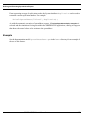
An example using the Evaluate function is a system with a processing time (Delay) that is a function
of an Entity Attribute. Select the Evl(1.0) function on the Duration Value field from the Delay
Activity’s Properties dialog. Clicking the Detail button will open an Evaluate dialog where the
Expression describing the processing time is entered. This example reads the Entity’s processing time
(given by the Entity Attribute ProcTime) and multiplies it by 1.5. This value would then be the delay
time for the Activity. Entity.ProcTime could be typed in directly or selected from the Global
Attributes list. Once selected in the Global Attributes list, the attribute can be added to the Expression
by selecting Add Selection to Evl.
SIMPROCESS User’s Manual
54
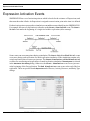
Expression Activation Events
Expression Activation Events
SIMPROCESS has a set of activation points at which it checks for the existence of Expressions, and
then runs those that it finds. An Expression is assigned to an activation point at the time it is defined.
Each activation point corresponds to a simulation event and has a name identifying it to SIMPROCESS.
For example, the start of a replication is referred to as the Start Simulation event. The Start
Trial event marks the beginning of a single trial within a replication (after warmup).
Some events can occur many times during a simulation. The Start Trial and End Trial events
occur once during each replication of a multi-replication simulation. If the simulation contains only
a single replication, these events occur just once. The Start Simulation and End Simulation
events occur once during each replication of a multi-replication simulation if Reset System is selected
in the Simulation Run Setting dialog. Otherwise, the Start Simulation event occurs just once
at the beginning of the first replication. The End Simulation event occurs at the end of the last
replication. These are specified on the Expressions tab of Process, Activity, Resource, and Entity Type
dialogs.
SIMPROCESS User’s Manual
55
Expression Activation Events
Start Run and End Run are Model Expressions only (menu Define/Model Expressions or the Define
Model Expressions button on the Model Toolbar). These Expressions are executed only once no matter
how many replications are run. Start Run is the very first Expression executed, and End Run
is the very last Expression executed. These Expressions are particularly useful for opening and closing
files that are needed throughout the simulation. (See “Methods OpenFile, CloseFile, ReadFromFile,
and WriteToFile” for information on opening and closing files.) The Start Simulation and
Start Trial Model Expressions are executed before the Start Simulation and Start
Trial Expressions of Entity Types, Resources, Activities, and Processes. The End Simulation
and End Trial Model Expressions are executed after the End Simulation and End Trial
Expressions of Entity Types, Resources, Activities, and Processes.
Events related to Entities and Resources can occur numerous times throughout a simulation trial. For
example, an Entity’s arrival at an Activity is a simulation event called Accept Entity (so-called
because the Entity is being accepted into the Activity). This can occur thousands of times during a
long simulation, once for each Entity that arrives at the Activity.
Every Expression is associated with a specific SIMPROCESS model element. Select the model element
that requires customized processing, specify the event at which the processing is to occur, and then
write the Expression to do the processing. “Example: Batching Entities Based on Weight” on page 60,
describes this Process in detail.
Not every event is available as an activation point for every model element. For example, the initial
value of an Attribute for an Entity can be set when the Entity is first generated (Initialize
Entity), or when the Entity is released from a Generate Activity (Release Entity). But the
value of an Entity Attribute cannot be set when the simulation first begins to run (Start
Simulation), because no Entities have been generated at that point.
The table below contains a complete list of activation events. Note that the order of the elements is
the order in which the Expressions are executed.
SIMPROCESS User’s Manual
56
Expression Activation Events
Event Name
Activation Point (and Comments)
Model Elements
Active For:
Start Run
The beginning of a simulation run. Occurs
only once, no matter how many replications.
Model.
Start Simulation
The beginning of the first replication, before
the warm-up period (if any). If Reset
System is selected, it occurs at the beginning of each replication.
Model.
Entity Types.
Resources.
All Activities.
Start Trial
Beginning of a trial within the simulation,
after the warm-up period (if any).
Model.
Resources.
Entity Types.
All Activities.
Initialize Entity
Creation (allocation) of an Entity.
Entity Instances.
Entity Types.
This typically occurs in a Generate Activity,
but may also occur in the Batch, Transform,
Copy, Split, and Assemble Activities.
Accept Entity
Arrival of an Entity at an Activity or Process.
Processes plus all Activities
except Generate.
Entity Instances.
Get Resource
Obtainment of a Resource by an Activity.
Resources.
All Activities except
Generate, Free Resource, &
Dispose.
Interrupt Processing
Entity processing is interrupted by a higher
priority Entity or by a Resource going
down.
Entity Instances.
Resume Processing
Entity processing is resumed after interruption.
Entity Instances.
Free Resource
Release of a Resource by an Activity.
Resources.
All Activities except Generate, Get Resource, & Dispose.
SIMPROCESS User’s Manual
57
Expression Activation Events
Event Name
Activation Point (and Comments)
Model Elements
Active For:
Release Entity
Release of an Entity from an Activity or
Process.
Processes plus all Activities
except Dispose.
Entity Instances.
Dispose of
Entity
Dispose of an Entity.
Entity Instances.
Entity Types.
Start Downtime
Resource initiates a downtime.
Resources.
End Downtime
Resources ends a downtime.
Resources.
End Trial
End of a simulation trial.
Model.
Entity Types.
Resources.
All Activities.
End Simulation
The end of a simulation replication.
Model.
Entity Types.
Resources.
All Activities.
Statistic collection for the replication ends
at this point.
End Run
The end of a simulation run. Occurs only
once at the end of all replications.
SIMPROCESS User’s Manual
Model.
58
Attribute Value Initialization
Attribute Value Initialization
User-defined Attributes can be initialized at several places in a SIMPROCESS model. The following
procedure shows how SIMPROCESS sets Attribute values along the simulation time line.
When the simulation is started, SIMPROCESS will:
1.
2.
Initialize Attributes to the values that are specified in the Attribute Definition dialog
Execute the reset system mechanism if the Reset System option is selected and Do Not Reset
Before Each Replication is not selected (reset Attribute to the values specified in the Attribute
Definition dialog)
3.
Execute any Start Simulation Expressions (Attributes can be set to different values in these
Expressions).
After a replication is complete, SIMPROCESS may reset Attribute values for the next replication. If
the Reset System option is selected in Run Settings, SIMPROCESS will continue on the next replication
starting from item 2, as listed above. Otherwise, it will start from item 3.
SIMPROCESS User’s Manual
59
Example: Batching Entities Based on Weight
Example: Batching Entities Based on Weight
This example describes a method of releasing Entities based on weight, an Attribute that
SIMPROCESS is not inherently aware of. The model depicts the product distribution Process of an
appliance manufacturer. Here is a simplified view of the model:
1.
Appliance orders are received from customers.
This is the Generate Activity. Each appliance order is an Entity.
2.
The orders are processed and eventually make their way to a distribution center in the form
of appliances.
This takes place within a subprocess. The details are not important for this example.
3.
Appliances are shipped to customers from the distribution center. A Batch Activity is used
to ship appliances as a group.
Shipments are released when the total weight of all appliances awaiting delivery reaches 5000
pounds.
In order to accomplish the objective of releasing the batch when a certain weight is accumulated, do
the following:
1.
Define Attributes to represent the weight Attribute of Entities (define global Entity Attribute
applianceWeight).
2.
Assign values to the weight Attributes.
3.
Accumulate and track the weight of Entities received at the Batch Activity (define local
Attribute at Batch Activity named batchWeight).
4.
Trigger the release of Entities if a specified weight is reached, and prevent the release of
Entities otherwise.
Build Process Flow
Open a new model and place a Generate Activity, Process, Batch Activity, and Dispose activity on
the layout. Connect the Activities. Descend into the Process and connect the incoming Input Pad to
the outgoing Output Pad. The details of the Process are not important for this example.
SIMPROCESS User’s Manual
60
Example: Batching Entities Based on Weight
Initializing Entity Attributes
First, assign a value to the applianceWeight of each Entity generated during a simulation. This can
be done as soon as the Entity is created. Then, when the Entity reaches the Batch Activity, add its weight
to a running total and compare this total to the maximum allowable weight. The points in the simulation
where Expressions need to be activated are:
•
•
Entity initialization
Receipt of the Entity by an Activity.
Entities are initialized by SIMPROCESS at the Initialize Entity event. Entities are received
by an Activity at the Accept Entity event.
Initialize Entity
Accept Entity
Defining the Expression at Entity Initialization
To assign an initial value to an Entity’s applianceWeight, define an Expression for each type of
Entity in the model. The Expression is a single assignment statement (e.g., applianceWeight :=
1000.0) to be executed when the Entity is first generated (the Initialize Entity event):
1.
From the Define pull-down menu, select Entities.
SIMPROCESS User’s Manual
61
Example: Batching Entities Based on Weight
2. This model contains three Entity types. An Expression must be defined for each Entity. Start
by selecting the first Entity on the list, and then press Edit.
3. Every refrigerator-order Entity that is generated needs to be initialized, so select the Entity
Expressions tab.
4. Six simulation events are listed on the Entity Expressions tab. These are the points during the
simulation at which SIMPROCESS checks for Expressions which apply to Entity instances.
The event needed is Initialize Entity, which is the point at which an Entity is first
generated (initialized). Highlight Initialize Entity and click on Edit.
5. SIMPROCESS invokes the Expression Editor and opens an Expression script dialog. Add just
one line to the text dialog:
applianceWeight := 1000.0;
This assigns a value of 1000.0 to applianceWeight.
6. Close the editor.
7. Follow the same procedure for each of the Entities in the model, but assign them different
weights. Assign a weight of 100.0 to television-order and 10.0 to toaster-order.
8. Click OK when finished.
Defining the Expression When an Entity Is Released
The method described above works fine to initialize the applianceWeight Attribute of Entities.
It’s fairly simple, too; it requires only a single statement in each Expression. But it is redundant in that
Expressions must be defined for each type of Entity. Defining an Expression for each Entity would
be tedious and time consuming if there are many different types of Entities.
There are other options. A weight does not have to be assigned to the Entities as soon as they are created.
SIMPROCESS User’s Manual
62
Example: Batching Entities Based on Weight
All that is required is the weight be assigned before the Entity reaches the Batch Activity where
appliances are distributed (DISTRIBUTE-ORDERS).
In this model, all Entities are generated by a single Generate Activity. So an Expression can be defined
in the Generate Activity that activates whenever an Entity is released (Release Entity event).
This is the most efficient way to proceed. One Expression handles the initialization of any Entity’s
applianceWeight.
1. Double-click on the Generate (RECEIVE-ORDERS) Activity.
2. In the Generate Activity Properties dialog, click on the Expressions tab. Five simulation events
are listed. The first, Start Simulation, will occur before any Entities are generated. Start Trial
will occur before any Entities are generated if there is no warmup period; otherwise, some
Entities could be generated if Entity generation was scheduled during the warmup period.
Release Entity serves the purpose, so highlight it and click on Edit.
3.
Enter the following lines in the Expression dialog:
IF Entity.Name = "refrigerator-order"
Entity.applianceWeight := 5000.0;
ELSIF Entity.Name = "television-order"
Entity.applianceWeight := 100.0;
ELSE
Entity.applianceWeight := 10.0;
END IF;
These instructions check the name of the Entity being released at the Activity. The name
identifies the type of Entity. A value is assigned to applianceWeight based on the Entity
type.
4. Close the editor.
5. Click on Close, and then OK.
Releasing Entities Based on Weight
Two more Expressions are needed to complete the model. In the first Expression, check the weight
of the Entities received at the batch Activity and trigger their release if the weight reaches a certain
number:
1.
Double-click on the DISTRIBUTE-ORDERS Activity.
2.
In the Batch Activity Properties dialog, click on the Expressions tab.
SIMPROCESS User’s Manual
63
Example: Batching Entities Based on Weight
3.
There are eight activation events listed on the Expressions tab for a Batch Activity. Accept
Entity occurs when an Entity arrives at the Activity, so highlight this event and click on Edit.
4.
Insert the following code:
batchWeight := batchWeight + Entity.applianceWeight;
IF batchWeight >= 5000.0
MaxBatchSize := NumberIn;
OUTPUT("Batch weight is ", batchWeight);
batchWeight := 0.0;
END IF;
In this Expression, the weight of the just-received Entity is added to the total weight of all
Entities received. If the total weight exceeds 5000.0, a batch release is triggered by resetting
MaxBatchSize, the Attribute that sets the maximum number of Entities that can be held
in the batch. With the Activity about to be emptied of Entities, the batchWeight Attribute
is reset to zero.
The OUTPUT statement in the Expression is there as an example of displaying information
in the message dialog. It is not needed by the model. OUTPUT statements can be interspersed
in Expressions in order to trace events during a simulation. Displaying the value of
batchWeight, for instance, verifies that the batch is really released when the weight
exceeds 5000.0.
5. Close the Accept Entity editor.
6. Edit the Start Simulation event. Enter the code below. This causes the Batch Activity
to wait for the logic in Accept Entity to cause a batch release.
MaxBatchSize := 10000;
7. Close the Start Simulation editor.
There is one more thing this model needs. The maximum batch size must be reset again after the Entities
are released. Entities should not be released when the DISTRIBUTE-ORDER batch reaches a certain
number. Only accumulating 5000 pounds of weight should trigger release.
As it stands now, MaxBatchSize is set to the size of the previous batch accumulated at the Activity.
This was done to force a release of Entities when batchWeight reached 5000 pounds. The number
of Entities could reach the current MaxBatchSize again before accumulating 5000 pounds of
weight. To prevent that, reset this Attribute to a number that can not possibly be reached before
accumulating 5000 pounds of weight:
1.
In the Expressions tab, select Release Entity. This is the event where the Entities are released
from the batch Activity.
Press Edit.
SIMPROCESS User’s Manual
64
Example: Batching Entities Based on Weight
2. Enter the following statement:
MaxBatchSize := 100000;
3. Close the editor.
The model should now be ready to run.
An Alternative Method Using Entity Types
This example works fine, but there are alternative approaches (as there often are when building models
in SIMPROCESS).
A couple of alternatives have already been described for initializing the value of the
applianceWeight Attribute (“Defining the Expression at Entity Initialization” on page 61 versus
“Defining the Expression When an Entity Is Released” on page 62). Another alternative involves
defining the applianceWeight Attribute for Entity types instead of Entity instances.
In this example, a weight Attribute was defined for every Entity instance in the model. Every
refrigerator order was assigned a weight of 5000, every television order, 100, etc. The assigned weights
remained unchanged during the course of the simulation.
Another approach would be to define an applianceWeight Attribute for each Entity type and
initialize it at the Start Simulation event. Then, in the Expression defined at Accept Entity
for the DISTRIBUTE-ORDERS Activity, the Entity’s weight would be referenced as:
Entity.Type.applianceWeight
This would work fine for this example. But suppose that the weight of an order could be affected by
some step in the Process being modeled and this needed to be reflected in the model. For example,
a customer order could include accessories for an appliance (e.g., cables and remote control for a
television), adding to the weight of the order. In that case, attaching the applianceWeight Attribute
to each Entity instance allows the weight of each television order to vary, which cannot be done if the
Attribute belongs to the Entity’s type.
Using Object Attributes in Expressions
The code in this example uses an Expression language construct referred to as a qualified reference.
For instance:
Entity.Name
refers to an object, named Entity, and an Attribute, Name.
SIMPROCESS User’s Manual
65
Example: Batching Entities Based on Weight
An object Attribute leads SIMPROCESS to the model element containing the Attributes of interest.
Unlike other Attributes, the value of the object is not of interest, only the values of its system or user
Attributes.
In step 3, the type of Entity being released by the Generate Activity was identified. The System Attribute
Name identifies the Entity type. But a Name Attribute also identifies Resources and Activities. So
referring to Name alone is ambiguous. In fact, SIMPROCESS assumes the reference is to the model
element that called the Expression (the RECEIVE-ORDERS Activity). To avoid confusion in the
Expression, always qualify Attributes with the object name such as (Entity.Name, Self.Name,
Activity.Name, Self.myattribute, etc.).
That is where object Attributes come in. They identify the model element of interest.
•
The Entity object Attribute tells SIMPROCESS to look at the Entity being processed in
the current Activity.
•
An Attribute called Self points at the current model element; that is, the model element the
Expression has been invoked from.
So Entity.Name returns the type name of the Entity instance being processed at the RECEIVEORDERS Activity, while Self.Name returns the name “RECEIVE-ORDERS.”
A qualified reference is also employed to set the User Defined Attribute applianceWeight:
Entity.applianceWeight := 5000.0;
Now, applianceWeight was specifically defined as an Attribute of Entities. However, this does
not mean that any reference to this Attribute would be unmistakable, that it can only refer to one thing.
But in fact, the reference to applianceWeight must be qualified by an object reference. This is
because without specifying a qualifier, SIMPROCESS assumes the reference is to an Attribute of the
current model element. In this case, the current model element is the Generate Activity, RECEIVEORDERS, since it is the model element which invoked the Expression. There is no Attribute named
applianceWeight associated with this Activity, and an unqualified reference to
applianceWeight would result in an error.
Note that an unqualified reference to the Attribute Name refers to the name of the current model element,
RECEIVE-ORDERS. If that is the Attribute of interest, the Attribute does not have to be qualified.
Object references can be stacked to gain access to variables that may not be within the scope of the
current object but may still be of interest in an Expression. For example, the following Expression
snippets are valid uses of object references from within an Activity Expression under the Accept Entity
event.
OUTPUT("In ",Self.Name, " Entity = ", Entity.Name);
SIMPROCESS User’s Manual
66
Example: Batching Entities Based on Weight
{ produces the name of the Activity and the name of the current
Entity }
OUTPUT("In ",Self.Name, " Entity Type = ", Entity.Type.Name);
{ produces the name of the Activity and the name of the current
Entity’s type }
OUTPUT("In ",Self.Activity.Name, " Entity = ",
Activity.Activity.Entity.Name);
{ produces the name of the Activity and the name of the current
Entity }
Notice in the third OUTPUT example, the object reference to the current Activity is stacked. In other
words, the Object Self points to itself, and the Activity object also points to the current Activity. This
is basically a circular reference and does not really do anything other than slow down the simulation
and confuse anyone that may read the Expression (something like
Activity.Activity.Activity.Entity.Name could also have been used which is the same
result but is even more confusing). The Expression language allows this feature so that access can be
gained to certain objects when appropriate. Consider the following example from within a Resource
Expression under the Get Resource event:
OUTPUT("In ",Self.Name, " Activity.Entity.Name
Activity.Entity.Name);
= ",
{ produces the name of the Activity and the name of the current
Entity in that Activity }
The above statement gains access to the Entity in the Activity that is assigning the Resource. When
using the stacked object references, pay close attention to what is the current state of the model. Consider
the following example for an Entity Expression under Initialize Entity event.
OUTPUT("In ",Self.Name, " Activity = ", Activity.Name);
{ produces an error
}
The above OUTPUT statement produces an error since there is no Activity object in scope at the time
an Entity is initialized. An Entity must be accepted into an Activity before the above statement would
work. This is a good example of being aware of the state of the simulation when referencing objects.
Other common mistakes are using the Resource object references (for example,
Resource("myResource").Activity.Name from within an Activity Expression before the
Get Resource event has occurred) or Sibling and Child references without considering the state
of the Siblings and Children (for example, Sibling("Delay6").Entity.Name may produce
an error if there is no Entity current in the Delay6 Activity).
SIMPROCESS User’s Manual
67
Example: Batching Entities Based on Weight
Object references are very powerful but can be confusing. It is recommended that the simplest form
possible of object reference be used in Expressions and that objects be accessed from the most obvious
point of scope (i.e., placing the Expressions behind the appropriate events).
The use of object reference also applies to the Child, Parent, and Sibling references. Any
number of object references can be stacked and return appropriate results unless a Child or Sibling
is referenced that does not exist, or a Parent is referenced from the top-level diagram - all of which
will return an error and terminate the simulation. The following example would work in a Process
Expression as long as it was invoked from a Process that is at least three levels deep, has a Sibling
named "Delay6", and a Child named "Delay7":
OUTPUT("In ",SelfName, " Sibling = ", Sibling("Delay6").Name,
Child("Delay7").Name), " two parents up = ",
Self.Parent.Parent.Name;
{ produces the name of the Activity, the name of Delay6, the name
of Delay7, and the name of the parent’s parent of the current
Process }
There are certain cases where it may be necessary to use object references as variables to gain further
control over what Attributes can be accessed or to provide some flexibility in an Expression. There
are basically two ways to use object references in variables: define local script variables of type
ANYOBJ, or define SIMPROCESS user-defined variables of type Object. Note that both of these
applications allow the variable to be setup as an array (just like any other variable type). Consider the
following examples:
{ this expression is placed in the Accept Entity event of an Activity
that has two local attributes defined - Attribute1 is a String
and Attribute2 is of type Object }
myobj : ANYOBJ;
myobjarray[5] : ANYOBJ;
myobj:=Self;
{ points to the Activity the script is in
}
myobjarray[0]:=Activity.Entity;
{ points to the current Entity in the Activity }
myobjarray[1]:= Sibling("Delay6");
{ points to a sibling Activity called Delay6 }
SIMPROCESS User’s Manual
68
Example: Batching Entities Based on Weight
myobjarray[2]:= Resource("myResource");
{ points to a Resource defined in the model }
Self.Attribute1:="hello dolly";
Self.Attribute2:=myobjarray[0];
{ points to the Activity.Entity object assigned to cell 0 of
myobjarray above }
Self.Attribute2:=myobjarray[1];
{ now points to the sibling Delay6 assiged above}
myobj.Attribute1:="hey mister";
{ replaces the value in attribute1 with the new string "hey mister"
since myobj also points to self - see above }
myobjarray[4]:=myobj.Entity.Type;
{points to the Entity type of the current Entity in the current
Activity }
myobjarry[5]:= myobj;
{ produces an error since myobjarray has only cells 0 - 4 defined
- the subscript is out of bounds ]
Type checking is done on the assignment of variables where possible. This is to prohibit assigning
basic type (REAL, INTEGER, STRING, etc.) variables to Object-type variables. Likewise, it precludes
assigning object references to basic types. The following lines in the same script above would produce
errors, and the simulation would terminate.
myobj := "hello dolly";
{produces an error because myobj is of type ANYOBJ and "hello dolly"
is of type String }
Self.Attribute1:=Entity;
{produces an error because Attribute1 is of type String and Entity
is of type object }
Note (as seen in the examples above) that type checking is not done between object type variables.
For example, if an Entity object is assigned to a variable defined as an object, an Activity or Resource
SIMPROCESS User’s Manual
69
Example: Batching Entities Based on Weight
object can be assigned to that same variable without causing any errors. However, the Expression may
not work properly if the variable should contain an Entity object reference and another object type
has been assigned to it.
There are a few special rules on object references. Self and Model object references can only be used
as the first reference in an Expression statement. Something like
myobj:=Self.Activity.Self;
results in an error, since Self can only appear as the first object reference qualifier for the statement.
SIMPROCESS User’s Manual
70
Getting and Freeing Resources Using Expressions
Getting and Freeing Resources Using Expressions
There are two system methods for getting and freeing Resources: GetResource and
FreeResource. “SIMPROCESS System Methods” summarizes the methods. These system
methods provide the same basic capability as the Get Resource and Free Resource Activities. (See
“Get Resource and Free Resource Activities”.) The main difference is that with the GetResource
system method, the Resource requested can be different for every Entity. The Get Resource Activity
assumes each Entity entering the Activity requires the same Resources. Thus, if different Resources
are needed, the Entity must be routed to a different Get Resource Activity that requests those Resources.
The demonstration model, H2O.spm, which is included in the SIMPROCESS installation, compares
the usual method of obtaining resources with the GetResource system method. The model is
described in Chapter 5 of the SIMPROCESS Getting Started Manual (Demonstration and Reference
Models).
GetResource
GetResource can be used in several Activities that can acquire Resources (Get Resource, Delay,
Branch, Transform, Gate, Synchronize, and Assign Activities). The Expression to get a Resource must
go in the Accept Entity Expression of the Activity. GetResource may not be used in an Entity, Entity
Type, or Resource Expression. The full command is
GetResource("Resource", "Units", "Tag");
The first parameter must be a String and is the Resource name. The second parameter can be a String,
Integer, or Real. This is the number of units of the Resource to acquire. By allowing the second
parameter to be a String, distributions can be used. The third parameter must be a String, but it is
optional. This parameter corresponds to the tag used in the Get Resource Activity. The tag defaults
to any tag! if the third parameter is omitted. If multiple GetResource system methods are used
at an Activity, the Resources are obtained based on the rule set in the Resource usage of that Activity.
The rules are Any One Member, All Members, Reserve As Available, and Number of Members. The default
is Any One Member. Therefore, if multiple GetResource system methods are used, only one of the
Resources will be acquired if the Resource acquisition rule has not been set to All Members. No
Resources have to be listed in the Resource usage dialog for the Resource acquisition rule to be set.
When requesting Resources on the Resources tab of Activity properties, a particular Resource can only
be added to the Requirements once. Thus, the selected acquisition rule always applies to different
Resources. However, since a GetResource system method is equivalent to a Resource listed under
Requirements, if two GetResource system methods in the same Activity reference the same
Resource then each GetResource request is treated in the same manner as if each referenced
different Resources. For example, assume the following statements are in the Accept Entity expression
of an Activity.
SIMPROCESS User’s Manual
71
Getting and Freeing Resources Using Expressions
GetResource("Resource1", 1);
GetResource("Resource1", 1);
If the acquisition rule is Any One Member, then only one unit of Resource1 will be acquired since each
statement is considered a "Member". If All Members is selected, then two units of Resource1 will be
acquired. Note that if Resource1 only has one unit defined, then the above statements will generate
a runtime error if All Members or Reserve As Available (which requires all members) are selected.
FreeResource
FreeResource can be used in several Activities that can release Resources (Free Resource, Delay,
Branch, Transform, Gate, Synchronize, and Assign Activities). Just like GetResource,
FreeResource must be used in the Accept Entity Expression of the Activity, and FreeResource
may not be used in an Entity, Entity Type, or Resource Expression. Both of these methods must go
in the Accept Entity Expression because these methods set up the requests for the events to occur while
the Entity is processing in the Activity. Therefore, order within the Accept Entity Expression does not
matter. A FreeResource system method for a particular Resource can come before the
GetResource, since this is occurring when the Entity is being accepted into the Activity. However,
since these system methods operate like the Activities of the same name, the FreeResource for
a particular Resource can be in a different Activity from the GetResource for that Resource. If the
FreeResource is in a different Activity, the Resource will not be released until the Entity has
completed processing in that Activity, even though the FreeResource system method is in the
Accept Entity Expression. The full command is
FreeResource("Resource", "Tag", TRUE);
The first parameter must be a String. It is the name of the Resource to be released. The second parameter
must be a String as well. This is the tag of the Resource to be released. The third parameter is a Boolean
(thus only TRUE and FALSE are allowed). For consumable Resources, this determines whether the
Resource should be consumed. The third parameter is optional. If omitted, it defaults to TRUE
(meaning the Resource should be consumed). This parameter has no effect on non-consumable
Resources. The second parameter (tag) is also optional. However, if the second parameter is omitted,
the third parameter must also be omitted. The tag defaults to any tag! if the tag parameter is missing.
There are two keywords for this system method: AnyResource and AnyTag. These can be used
in the place of the Resource parameter and the tag parameter. So possible options are (without the last
parameter):
•
•
•
•
•
FreeResource("Resource1", "myTag");
FreeResource("Resource1", "AnyTag");
FreeResource("Resource1"); this operates the same as the previous
FreeResource("AnyResource", "myTag");
FreeResource("AnyResource", "AnyTag");
SIMPROCESS User’s Manual
72
Getting and Freeing Resources Using Expressions
•
FreeResource("AnyResource"); this operates the same as the previous
These are the same combinations that are available in the Free Resource Activity. The following
example shows getting and freeing a Resource at a typical Delay Activity.
GetResource("Sales Rep", 1);
FreeResource("Sales Rep");
Combining Get and Free Expressions With Activities
These system methods can be used with the Get Resource and Free Resource Activities. Any Resource
obtained with the GetResource system method can be released by a Free Resource Activity.
However, it is important to note that tags used in a GetResource system method will not be available
in a Free Resource Activity if those tags have not been used in a Get Resource Activity. Likewise,
any Resource obtained with a Get Resource Activity can be released with a FreeResource system
method.
SIMPROCESS User’s Manual
73
Creating Resources Using Expressions
Creating Resources Using Expressions
For most models, Resources are defined when the model is created using the Define/Resources menu
item. (See “Resource Modeling Constructs”.) This is done because the Resources that are required
by the model are known when the model is created. However, there are times when the design of the
model requires that the model be configured from an outside source (such as a database). In this instance,
the number of resources and their characteristics may not be known until runtime. In this scenario,
the model is typically run without the SIMPROCESS Graphical User Interface (GUI) using the
SIMPROCESS Dispatcher or other methods for running a model apart from the SIMPROCESS GUI.
(See “Running Models Without GUI”.) There are four system methods for creating and configuring
Resources: CreateResource, SetResourceCost, SetResourceDowntime, and
SetResourceExpression. “SIMPROCESS System Methods” summarizes the methods.
SetResourceCost, SetResourceDowntime, and SetResourceExpression can be
used with Resources created using CreateResource or with Resources defined when creating the
model (Define/Resources).
These system methods are not intended for the novice user. The proper use of these system methods
requires indepth knowledge of simulation modeling and SIMPROCESS.
CreateResource
This statement creates a new Resource within a SIMPROCESS model. CreateResource can only
be used in the Start Run Expression (Define/Model Expressions or the Define Model Expressions button
on the Model Toolbar). Resources cannot be created during a trial or between replications. The full
command is
CreateResource(Name:STRING, Units:REAL, Fractional:BOOLEAN,
Consumable:BOOLEAN, ResourceStats:BOOLEAN,
ResourceByActivityStats:BOOLEAN, ResourceByShiftStats:BOOLEAN);
The first parameter is a String and must be a unique Resource name. The second parameter sets the
starting capacity of the Resource. The parameters Fractional, Consumable,
ResourceStats, ResourceByActivityStats, and ResourceByShiftStats must be
TRUE or FALSE. Fractional Resource usage is allowed if the Fractional parameter is TRUE. The
Resource will be consumed when released if the Consumable parameter is TRUE. (Note that
consumable Resources created with CreateResource can only be replenished by using the
IncreaseCapacity system method.) Resources created at runtime will have statistics collected
if Collect Resource Statisitics or Collect Resource by Activity Statistics are selected on the Statistics
Collection dialog (Report/Define Global Statistics Collection, see “Default Performance Measures”).
Statistics will also be collected if ResourceStats, ResourceByActivityStats, and/or
ResourceByShiftStats are set to TRUE. The ResourceByShiftStats parameter is
SIMPROCESS User’s Manual
74
Creating Resources Using Expressions
optional. If omitted FALSE is assumed.
For example, consider a scenario where the Resources for a model are stored in a database. The
following code (in the Start Run Expression) reads the database and creates the Resources. (RunId
and Database are Model Attributes which were previously initialized.)
sql : STRING;
name : STRING;
units : REAL;
sql := "Select Name, Units from Resource_Table where RunId=" +
INTTOSTR(Model.RunId);
ReadFromDatabase(Model.Database, "Set", sql);
WHILE GetNext("Set")
name := GetResult("Set", "Name");
units := GetResult("Set", "Units");
CreateResource(name, units, FALSE, FALSE, FALSE, FALSE, FALSE);
END WHILE;
Once a Resource has been created, other characteristics can be set (Cost, Downtime, and Expressions).
Note that local Resource Attributes cannot be created through Expressions. However, global Resource
Attributes can be used by Resources created using CreateResource. Most likely, other global
Resource Attributes would be created to hold information about the Resource, such as ID or
Description. The value of these Attributes would be obtained from the external source.
SetResourceCost
SetResourceCost is used to set the value of a Resource cost. (See “Activity-Based Costing”.)
A nonconsumble Resource can have four types of cost, three of which are variable and one that is fixed.
A consumable Resource can have two types of cost, both of which are variable. This system method
is not limited to the Start Run Expression. It can be used at any point during a simulation run. However,
changes to cost values made during a run will not take effect until a new cost period begins. The full
command is
SetResourceCost(ResourceName:STRING, Cost:REAL, CostType:STRING,
TimeUnit:STRING);
ResourceName is the name of the Resource to which the Cost applies. The Cost must be greater
than or equal to zero. For a nonconsumable Resource, CostType can be PerEntity, PerUnit,
PerTimeUnit, or Fixed. CostType can only be PerEntity or PerUnit for a consumable
Resource. When the CostType is PerTimeUnit, the TimeUnit must be one of the valid
SIMPROCESS time units (Nanoseconds, Microseconds, Milliseconds, Seconds,
Minutes, Hours, Days, Weeks, Months, Years). When the CostType is Fixed, the
SIMPROCESS User’s Manual
75
Creating Resources Using Expressions
TimeUnit must be Weekly, Monthly, Quarterly, Half-Yearly, or Yearly. If the
CostType is PerEntity or PerUnit, then the TimeUnit parameter can be omitted. If included,
it is ignored.
The example below expands on the previous example. In this example, after the Resources are created,
the costs will be set. The example assumes that the CostTypes retrieved from the database are in the
proper format. If this were not the case other logic would be required. Also, the time unit is retrieved
for every cost type. However, as stated above, this field is ignored by SetResourceCost if it is
not needed.
sql : STRING;
name : STRING;
units : REAL;
cost : REAL;
costType : STRING;
timeUnit : STRING;
sql := "Select Name, Units from Resource_Table where RunId=" +
INTTOSTR(Model.RunId);
ReadFromDatabase(Model.Database, "Set", sql);
WHILE GetNext("Set")
name := GetResult("Set", "Name");
units := GetResult("Set", "Units");
CreateResource(name, units, FALSE, FALSE, FALSE, FALSE, FALSE);
sql := Select Cost, CostType, TimeUnit from Cost_Table where
Resource=’" + name + "’";
ReadFromDatabase(Model.Database, "CostSet", sql);
WHILE GetNext("CostSet")
cost := GetResult("CostSet", "Cost");
costType := GetResult("CostSet", "CostType");
timeUnit := GetResult("CostSet", "TimeUnit");
SetResourceCost(name, cost, costType, timeUnit);
END WHILE;
END WHILE;
SetResourceDowntime
A globally defined Resource Downtime (see “Global Resource Downtime” on page 149) can be
applied to a Resource using the SetResourceDowntime command. As with CreateResource,
SetResourceDowntime can only be used in the Start Run Expression. The full command is
SIMPROCESS User’s Manual
76
Creating Resources Using Expressions
SetResourceDowntime(ResourceName:STRING, DowntimeName:STRING);
The ResourceName parameter is the name of the Resource to which the DowntimeName will apply.
Note that a global Downtime cannot be applied more than once to the same Resource.
The example below expands the previous example to include Downtime.
sql : STRING;
name : STRING;
units : REAL;
cost : REAL;
costType : STRING;
timeUnit : STRING;
downtimeType : INTEGER;
sql := "Select Name, Units from Resource_Table where RunId=" +
INTTOSTR(Model.RunId);
ReadFromDatabase(Model.Database, "Set", sql);
WHILE GetNext("Set")
name := GetResult("Set", "Name");
units := GetResult("Set", "Units");
CreateResource(name, units, FALSE, FALSE, FALSE, FALSE, FALSE);
sql := Select Cost, CostType, TimeUnit from Cost_Table where
Resource=’" + name + "’";
ReadFromDatabase(Model.Database, "CostSet", sql);
WHILE GetNext("CostSet")
cost := GetResult("CostSet", "Cost");
costType := GetResult("CostSet", "CostType");
timeUnit := GetResult("CostSet", "TimeUnit");
SetResourceCost(name, cost, costType, timeUnit);
END WHILE;
sql := Select DowntimeType from Downtime_Table where Resource=’"
+ name + "’";
ReadFromDatabase(Model.Database, "DTSet", sql);
WHILE GetNext("DTSet")
downtimeType := GetResult("DTSet", "DowntimeType");
{DowntimeType of 0 indicates no downtime}
IF downtimeType = 1
SetResourceDowntime(name, "StandardShift");
ELSIF downtimeType = 2
SetResourceDowntime(name, "NightShift");
END IF;
SIMPROCESS User’s Manual
77
Creating Resources Using Expressions
END WHILE;
END WHILE;
SetResourceExpression
Expressions can be assigned to Resources created using CreateResource through the use of text
files. The SIMPROCESS Expression Language code must be in a text file (ASCII) that is located in
the model’s directory. The code should be created and validated in SIMPROCESS before being saved
to a file. The SetResourceExpression statement links a text file to a particular Resource
Expression. The full command is
SetResourceExpression(ResourceName:STRING, ExpressionType:STRING,
ExpressionFile:STRING);
The ResourceName specifies the Resource to use. The ExpressionType must be Start
Simulation, Start Trial, Get Resource, Free Resource, Start Downtime, End
Downtime, End Trial, or End Simulation. ExpressionType is case sensitive.
ExpressionFile is the complete name of the text file that contains the Expression code. No path
is needed since the file must reside in the model’s directory.
The example below expands the previous example to include Expressions. In this example, the
proportion of time that the Resource is fully used needs to be determined. A global Resource Attribute
named MaximumUse of type INTEGER has been defined. Time-weighted statistics were selected
for the Attribute. In getresource.txt is the following code
IF UnitsBusy = Capacity
MaximumUse := 1;
ELSE
MaximumUse := 0;
END IF;
The following code is in freeresource.txt
MaximumUse := 0;
These files are used in the code below.
sql : STRING;
name : STRING;
units : REAL;
cost : REAL;
costType : STRING;
timeUnit : STRING;
SIMPROCESS User’s Manual
78
Creating Resources Using Expressions
downtimeType : INTEGER;
sql := "Select Name, Units from Resource_Table where RunId=" +
INTTOSTR(Model.RunId);
ReadFromDatabase(Model.Database, "Set", sql);
WHILE GetNext("Set")
name := GetResult("Set", "Name");
units := GetResult("Set", "Units");
CreateResource(name, units, FALSE, FALSE, FALSE, FALSE, FALSE);
sql := Select Cost, CostType, TimeUnit from Cost_Table where
Resource=’" + name + "’";
ReadFromDatabase(Model.Database, "CostSet", sql);
WHILE GetNext("CostSet")
cost := GetResult("CostSet", "Cost");
costType := GetResult("CostSet", "CostType");
timeUnit := GetResult("CostSet", "TimeUnit");
SetResourceCost(name, cost, costType, timeUnit);
END WHILE;
sql := Select DowntimeType from Downtime_Table where Resource=’"
+ name + "’";
ReadFromDatabase(Model.Database, "DTSet", sql);
WHILE GetNext("DTSet")
downtimeType := GetResult("DTSet", "DowntimeType");
{DowntimeType of 0 indicates no downtime}
IF downtimeType = 1
SetResourceDowntime(name, "StandardShift");
ELSIF downtimeType = 2
SetResourceDowntime(name, "NightShift");
END IF;
END WHILE;
SetResourceExpression(name, "Get Resource", "getresource.txt");
SetResourceExpression(name, "Free Resource",
"freeresource.txt");
END WHILE;
Resource Usage
Since the Resources required for the model are not defined when the model is created, it is impossible
to assign Resource usage on an Activity’s Resources tab. Thus, the GetResource and
FreeResource system methods must be used (page 71). The modeler must know which Activities
SIMPROCESS User’s Manual
79
Creating Resources Using Expressions
will require Resources, but the modeler does not have to know which Resources will be required or
the quantity of the Resources that will be required. For example the Accept Entity expression of the
Activity could contain
GetResource(Entity.ResName, Entity.ResQuantity);
FreeResource(Entity.ResName);
where ResName is a STRING Entity Attribute containing the name of the Resource, and
ResQuantity is a REAL or INTEGER Entity Attribute containing the number of units required.
Most likely, the values of these Attributes would be set by an outside source.
SIMPROCESS User’s Manual
80
Changing Resource Capacity With Expressions
Changing Resource Capacity With Expressions
IncreaseCapacity and DecreaseCapacity are system methods that will change the capacity
of a Resource during a simulation run. “SIMPROCESS System Methods” summarizes the methods.
The methods apply to all Resources, whether consumable or not. Thus, IncreaseCapacity could
be used to replenish a consumable Resource (however, the replenish to capacity option is not available).
Just as with consumable Resources, the statistics for a Resource will reflect increases or decreases in
capacity.
IncreaseCapacity
IncreaseCapacity can go in any type of Expression. When executed, it immediately increases
the number of units of the Resources. The command is:
IncreaseCapacity("Resource1", 2);
The first parameter must be a String. It is the name of the Resource to increase. The second parameter
must be an Integer or a Real. Even though the second parameter can be a Real, the number of units
to increase cannot be fractional (even if the Resource is a fractional Resource).
DecreaseCapacity
Just like IncreaseCapacity, DecreaseCapacity can go in any type of Expression. When
executed, it decreases the capacity of the Resource as units of the Resource become available. If the
number of units to decrease are less than the number of units idle, then the decrease happens
immediately. If not, then the capacity units are decreased as units go to idle. Note that if the request
for decrease is larger than the current capacity, SIMPROCESS will reduce the capacity to zero.
However, SIMPROCESS will keep track of the number of units not yet decreased. For example, if
Resource1 has a capacity of 3, and the capacity is decreased by 4, then the capacity of Resource1 is
zero. Then, if the capacity of Resource1 is increased by one, the capacity of Resource1 will still be
zero. This is because there was one unit of decrease still not applied to Resource1. The full command is
DecreaseCapacity("Resource1", 2);
The first parameter must be a String. It is the name of the Resource to decrease. The second parameter
must be an Integer or a Real. Even though the second parameter can be a Real, the number of units
to decrease cannot be fractional (even if the Resource is a fractional Resource).
DecreaseCapacity is not a substitute for the consuming of consumable Resources. Consumable
Resources will be consumed when released. It is not necessary to use a system method.
DecreaseCapacity is intended for non-consumable Resources.
SIMPROCESS User’s Manual
81
Setting Maximum Resource Wait With Expressions
Setting Maximum Resource Wait With Expressions
The Resources tab of Activity properties dialogs allows a maximum wait time to be set (see “Adding
Resource Requirements to Activities”). The maximum wait time is the maximum amount of time that
an Entity will wait for the requested Resources to be acquired. The same thing can be accomplished
using the Entity System Attribute MaxWait (see “System Attributes”). If the value for MaxWait is
greater than zero, then the Entity will exit the Activity without processing if Resources have not been
acquired by that time. Note that the time unit that applies to MaxWait is the Simulation Time Unit
specified in the Run Settings (see “Run Settings”). If greater than zero, the MaxWait System Attribute
overrides the Value set in the Maximum Wait for Resource Time section of the Resources tab of the Activity
properties dialog. MaxWait must be set in the Accept Entity Expression. For example putting
Entity.MaxWait := .25;
in the Accept Entity Expression means that the Entity will wait at most .25 time units (if the Simulation
Time Unit is Hours, then .25 represents .25 hours). The value for MaxWait must be reset to zero when
a maximum wait for Resources is no longer needed. MaxWait is not reset automatically. It is best
to set MaxWait to zero in the Release Entity Expression of the Activity where MaxWait was used.
Entity.MaxWait := 0.0;
When an Entity exits an Activity without processing, the Entity System Attribute EndWait is set to
TRUE. Thus, EndWait can be checked to determine whether an Entity exited an Activity without
processing and the Entity can be routed appropriately. Important: As with MaxWait, EndWait is
not automatically reset to FALSE. This must be done in an Expression once the current value of
EndWait is no longer needed for Entity routing.
Entity.EndWait := FALSE;
For Activities that collect statistics, Entity Counts for Entities that exit without processing are displayed
in the Total Not Processed category of the Activity Entity Count statistics (page 254) in the
Standard Report (page 243).
SIMPROCESS User’s Manual
82
User-Defined Functions
User-Defined Functions
A User-defined Function will return the value of an Expression each time it is called from within
the model. This allows re-use of a single function in multiple places in the model. A value must be
returned.
To create a User-defined Function, go to the Define menu, and select Functions or click the Define
button on the Model Toolbar. This opens a list box displaying any previously defined
Functions. The Expression Editor dialog opens for Add, Edit, and Copy. The Name of the function must
be unique across all Functions, Standard distributions, Tabular distributions, and Auto Fits
distributions. (See “User Defined Distributions” for information on defining Standard, Tabular, or Auto
Fits distributions.)
Functions
The final line of the Expression should be a RETURN statement such as:
RETURN (Entity.Time * Activity.Factor);
where Entity.Time and Activity.Factor are Attributes. Each time this Function is called,
it will return the value of the multiple of the two Attributes. Note that REAL, INTEGER, BOOLEAN
or STRING values can be returned. Also, the value received by the caller is always a REAL even if
an INTEGER value followed the RETURN.
The Name entered for the User-defined Function will appear in every combo box in the model where
a statistical distribution can be entered. Also, User-defined Functions can be used in Expressions by
using the Function system method. (See “SIMPROCESS System Methods”.) When a User-defined
Function is called by the Function system method, values can be passed to the Function directly
without using Attributes. Local variables must be defined to accept the incoming values. The local
variables must be named Arg1, Arg2,..., ArgN, and the types of the local variables (INTEGER, REAL,
etc.) must match the incoming values. Also, the local variables must be defined in order. That is, Arg1
must be defined before Arg2 and so on.
The text of a Function can be stored in an external file. See “Expression Editor,” beginning on page 47
for a discussion of that option.
SIMPROCESS User’s Manual
83
Dynamic Labels
Dynamic Labels
There are two types of background text in SIMPROCESS: static text and dynamic labels. Static text
is used for annotating the model layout and does not change during simulation. Dynamic labels, as
their name implies, are updated during simulation and are used to display information about changing
properties of model elements. One way to update dynamic labels is through the
UpdateDynamicLabel method in Expressions. (See “Background Text” for a discussion of the
other way to update dynamic labels.)
To update a dynamic label using Expressions, the dynamic label must have a unique combination of
Name and Id number. Usually, Id number will be 0, unless two dynamic labels have the same Name.
The name typed into the Name text box will not appear on the layout. It will only be used to reference
the label from the Expression builder. The type of value with which the dynamic label will be updated
must also be selected. The choice between String, Integer, and Real is made in the Mode combo box.
If the value of the dynamic label is Real, Width and Precision must be specified in the corresponding
value boxes. Width is the total number of digits that will be shown for the displayed value (including
the decimal point), while Precision specifies the number of digits after the decimal point that will be
displayed. If the Width is greater than the value being displayed, it will be padded with spaces on the
left side. If the Mode is Integer, then only the Width field needs to be set.
Note that the Value field does not have to be empty to use UpdateDynamicLabel. The same
dynamic label can be updated automatically and with UpdateDynamicLabel.
SIMPROCESS User’s Manual
84
Dynamic Labels
Once the dynamic label is defined, it can be updated by making a function call to the
UpdateDynamicLabel method in the Expression builder. This method requires the following five
arguments in this order:
MasterEditor — (typed as shown), reference to the main layout window.
name — a string (in quotes) used to designate the dynamic label in the Name text box of
Background Text dialog. Make sure letter case is the same in both places.
ID number — the integer in the Id box of the Background Text dialog.
text color — a string (in quotes) of the color in which the text is to appear. A list of
color names is found in “SIMPROCESS System Attributes and Methods”. As with name,
letter case must be as shown in the table. This overrides the font color selected in the
properties dialog.
value — integer, real, or string value to display; type must correspond to what was selected
in the Mode combo box of the Background Text dialog.
For example, to display a string showing the name of the Entity leaving a delay Activity, as well as
a real value showing the amount of time this instance of an Entity spent at the Activity, and an integer
showing number of Entities currently at that Activity, enter the following three commands in the
Expression builder of the delay Activity at the Release Entity entry point:
UpdateDynamicLabel(MasterEditor,"num",0,"Orange", NumberIn);
UpdateDynamicLabel(MasterEditor,"name",0,
"Aquamarine",Entity.Name);
UpdateDynamicLabel(MasterEditor,
"lastdelay",0,"IndianRed",LastDelay);
For more information on Expression builder terminology and syntax, see “SIMPROCESS System
Attributes and Methods”.
Note that both dynamic and static text font Attributes can be changed during simulation by selecting
the text and editing its properties. The change will take effect immediately after the Background Text
dialog is closed and the simulation is resumed.
SIMPROCESS User’s Manual
85
Interfacing With A Database
Interfacing With A Database
Expressions can retrieve information from an SQL database, and can modify an SQL database by
inserting into tables, deleting from tables, and updating tables. Knowledge of SQL is required since
all queries to the database are SQL queries. A sample model named DatabaseDemo.spm is part
of the ExpressionDemos directory.
Database System Methods
There are seven database-related System Methods which can be used in Expressions. (See
“SIMPROCESS System Methods”.)
•
•
•
•
•
•
•
OpenDatabase
CloseDatabase
ReadFromDatabase
WriteToDatabase
GetNext
GetResult
DisposeResultSet
OpenDatabase
OpenDatabase is used to create a connection between SIMPROCESS and a database. This must
be done before any other database System Methods are used (the Start Run Expression is a good place
to use it). Before using the method an Attribute must be defined (normally a Model Attribute) of type
Object. (See “User Defined Attributes” on page 28.) This Attribute will be used as a reference to the
database connection. The way to identify the database is through a database properties file. This file
should be similar in content to the sProcDB.properties file in the SPUser directory. This file
is used to connect SIMPROCESS to the database that comes with SIMPROCESS. (Note: Do not modify
sProcDB.properties. Copy the file before making changes.) Below is the contents of
sProcDB.properties.
jdbc.drivers=net.ucanaccess.jdbc.UcanaccessDriver
jdbc.url=jdbc:ucanaccess://SPUser/SimProcDB.mdb
jdbc.username=""
jdbc.password=""
Simply change each of the properties to reflect the protocols needed for the system. When using a
SIMPROCESS User’s Manual
86
Interfacing With A Database
database properties file the syntax is:
Model.ObjectAttribute := OpenDatabase("PropertiesFileName");
where PropertiesFileName is the name of the database properties file. The preferred location for a
properties file is the model’s directory. An alternative location is the SPUser directory. If not in one
of those two locations, the PropertiesFileName must include the complete path to where it can be found.
If the connection is successful, the Attribute will contain a reference to the connection. Note that the
connection is only valid for the model that created the connection. If another model needs to use the
same database, that model must create its own connection.
CloseDatabase
CloseDatabase is used to close a connection to a database and disposes all open Result Sets. This
normally occurs at the end of a simulation (End Simulation or End Run Expression). The syntax is
CloseDatabase(Model.ObjectAttribute);
The only parameter is the Object Attribute that was used in the OpenDatabase system method that
created the connection.
ReadFromDatabase
ReadFromDatabase gets information from a database and places the information into a Result Set.
GetNext and GetResult are used to assign the data from a Result Set to Attributes or local variables
in the model. The syntax is
ReadFromDatabase(Model.ObjectAttribute, "ResultSetName",
"SQLQuery");
Model.ObjectAttribute is the Object Attribute that was used in the OpenDatabase system
method that created the connection. ResultSetName is a unique string identifier for the Result Set
created by the query. SQLQuery is a string and is the query that creates the Result Set. Normally the
query would start with the SELECT command.
WriteToDatabase
WriteToDatabase is used to modify the tables of the database. Nothing is returned. The syntax is
WriteToDatabase(Model.ObjectAttribute, "SQLQuery",
CheckWarnings);
Model.ObjectAttribute is the Object Attribute that was used in the OpenDatabase system
method that created the connection. SQLQuery is a string and is the query that modifies the tables
SIMPROCESS User’s Manual
87
Interfacing With A Database
of the database. This query can start with INSERT, UPDATE, or DELETE. CheckWarnings is an
optional boolean parameter which defaults to TRUE if omitted. When TRUE, the check for SQL
warnings occurs. One or more warnings will cause a SIMPROCESS run time error. CheckWarnings
only needs to be used when SQL warnings should be suppressed (FALSE).
Note that WriteToDatabase can slow the simulation as table sizes increase. Also, be careful when
using WriteToDatabase if there is the possibility the simulation will be stopped early by user
intervention. Updates to the database can lag behind the simulation. Thus, if the simulation is stopped
early there is the potential that the CloseDatabase command would be executed before all the
WriteToDatabase commands have finished. The consequence would be an error that could
possibly crash SIMPROCESS. Omit the CloseDatabase command if this scenario might occur.
If the CloseDatabase command is omitted, SIMPROCESS will not release the database until
SIMPROCESS is closed.
WriteToDatabase can also be used with predefined SQL statements. See “Exporting Results” for
more information on defining SQL statements and executing with WriteToDatabase.
GetNext
GetNext controls the position within a Result Set. Result Sets are simply tables of data. The columns
are the fields requested in the SQL query. For instance, if the query was "SELECT CallTime,
WrapUpTime FROM Times" the columns in the Result Set would be CallTime and WrapUpTime.
GetNext sets the row of the Result Set. So GetNext is used in conjunction with GetResult.
GetResult gets a value from the table (Result Set) once the row has been set. When a Result Set
is first created by a ReadFromDatabase, the row pointer in a Result Set is pointing to before the
first row. Thus, GetNext must be called before GetResult. The syntax is
BooleanVar := GetNext("ResultSetName");
BooleanVar is any Attribute or local variable defined to be a BOOLEAN. TRUE is returned
if the next row exists, FALSE if not (at the end). ResultSetName is the user selected name
given to a Result Set by a ReadFromDatabase.
Note that GetNext only moves forward through the rows. Going backwards is not possible. The only
way to go back to the beginning of a Result Set is to execute again the ReadFromDatabase that
created the Result Set.
GetResult
GetResult assigns a value from a Result Set to an Attribute or local variable in the model. The value
comes from the current row of the Result Set. The current row is set by GetNext. The syntax is
Variable := GetResult("ResultSetName", "Field");
Variable can be an Attribute or a local variable. ResultSetName is the user-selected name
SIMPROCESS User’s Manual
88
Interfacing With A Database
given to a Result Set by a ReadFromDatabase. Field is the field from the database (column
of the Result Set) that has the desired value.
The type of the value returned (INTEGER, REAL, BOOLEAN, or STRING) to Variable must
match with the type of the Variable. Note that only INTEGER, REAL, BOOLEAN, and STRING
values can be placed in a Result Set.
DisposeResultSet
DisposeResultSet disposes of a Result Set created by the ReadFromDatabase statement.
Result Sets are disposed automatically when GetNext returns FALSE. This usually happens when
GetNext is used in a WHILE loop. Result Sets are also automatically disposed when the same Result
Set name is used in another ReadFromDatabase statement. Using GetNext with an IF statement
may leave a Result Set remaining in memory. DisposeResultSet ensures a Result Set is eliminated
from memory.
DisposeResultSet("ResultSetName");
SQL Tips
When writing to or reading from MS Access or MS SQL Server databases, table names should be
enclosed in square brackets ([]). See the examples in the section Database Example. Also, if writing
a date/time string to a Date/Time field in MS Access, the date/time string should be surrounded by
the # character. For example,
SQLString : STRING;
SQLString := "INSERT Into [ModelInfo] (RunDateTime) VALUES (#" +
SystemDateTime + "#)";
(SystemDateTime returns the date and time of the underlying system in the format MM/DD/YYYY
HH:MM:SS.) During execution the SQL would appear like this.
INSERT Into [ModelInfo] (RunDateTime) VALUES (#02/01/2015
10:45:52#)
Also, ensure all string values are surrounded by single quotes.
Database Errors
When an error occurs during any database operation, check the simprocess.log and
simprocess.err files for error information. The information in these files can be useful in finding
solutions. These files are located in the SIMPROCESS working directory (see “SIMPROCESS
SIMPROCESS User’s Manual
89
Interfacing With A Database
Working Directory”).
Database Example
The following are several examples on how to use the database System Methods. They are categorized
by Expression type. The SQL format is for MS Access so the table names are enclosed in square
brackets.
Start Simulation Example
This example assumes two real Model Attributes (CallTime and WrapUpTime) have been defined.
Each of the Model Attributes have an array size that is equal to or larger than the number of values
returned by the query. The values are placed in array Model Attributes because the values need to be
referenced throughout the simulation. Also an object Model Attribute (DatabaseConn) was defined
for the connection. Note that in the SQL query double quotes are required around the table name Times
Table (for MS Access). Double quotes can be placed in strings by using \".
SQLString : STRING;
count : INTEGER;
Model.DatabaseConn := OpenDatabase("MyDatabase");
SQLString := "SELECT CallTime, WrapUpTime FROM [Times Table] WHERE
Month = 12";
ReadFromDatabase(Model.DatabaseConn, "Times", SQLString);
count := 0;
WHILE GetNext("Times")
Model.CallTime[count] := GetResult("Times", "CallTime");
Model.WrapUpTime[count] := GetResult("Times", "WrapUpTime");
count := count + 1;
END WHILE;
End Simulation Example
This example just shows closing a connection.
CloseDatabase(Model.DatabaseConn);
Accept Entity Example
In this example an Entity enters an Activity and gets its delay time from the database. This assumes
the WHILE loop in the Start Simulation example was not performed.
SQLQuery : STRING;
IF GetNext("Times")
SIMPROCESS User’s Manual
90
Interfacing With A Database
Entity.Delaytime := GetResult("Times", "CallTime");
ELSE {will read again to start over if no more times are found}
SQLQuery := "SELECT CallTime, WrapUpTime FROM [Times Table]
WHERE Month = 12";
ReadFromDatabase(Model.DatabaseConn, "Times", SQLQuery);
IF GetNext("Times")
Entity.Delaytime := GetResult("Times", "CallTime");
END IF;
END IF;
Release Entity Example
This example shows writing to a database. The processing time of the Entity for the Process is placed
in the database in a table named ProcessTimes. The simulation time the Entity entered the Process
was stored in an Entity instance Attribute called StartTime.
SQLString : STRING;
time : REAL;
time := SimTime - Entity.StartTime;
SQLString := "INSERT Into [ProcessTimes] (ProcessTime) VALUES ("
+ REALTOSTR(time) + ")";
WriteToDatabase(Model.DatabaseConn, SQLString);
SIMPROCESS User’s Manual
91
Interfacing With A Spreadsheet
Interfacing With A Spreadsheet
Expressions can retrieve information from an Excel compatible spreadsheet, and can modify a
spreadsheet by inserting new Worksheets, values, and formulas. A sample model named
SpreadsheetDemo.spm is part of the ExpressionDemos directory.
Spreadsheet System Methods
There are four spreadsheet-related System Methods which can be used in Expressions. (See
“SIMPROCESS System Methods”.)
•
•
•
•
OpenSpreadsheet
CloseSpreadsheet
ReadFromSpreadsheet
WriteToSpreadsheet
OpenSpreadsheet
OpenSpreadsheet is used to create a connection between SIMPROCESS and an Excel compatible
spreadsheet file. This must be done before any other spreadsheet-related System Methods are used
(the Start Run Expression is a good place to use it). Before using the method an Attribute must be defined
(normally a Model Attribute) of type Object. (See “User Defined Attributes” on page 28.) This
Attribute will be used as a reference to the spreadsheet. The syntax is
Model.ObjectAttribute := OpenSpreadsheet("Mode", "FileName");
where Mode is either Input or Output. A spreadsheet file cannot be open for both reading and
writing at the same time. If FileName does not contain a path (the preferred method), the file’s
location will be the model’s directory. If the Mode is Input, the file must already exist.
Two different file types are supported: Workbook files (which usually have the .xls or .xlsx
extension) and Excel XML Spreadsheet files (which usually have the .xml extension). When a
spreadsheet is opened for Output and the file does not already exist, SIMPROCESS will create a
Workbook file that is compatible with any of the latest versions of Excel. If FileName has the extension
.xls an Excel 2003 compatible file is created. If FileName has the extension .xlsx an Excel 2007
compatible file is created. Also, the Workbook file is compatible with the Calc spreadsheet program
in OpenOffice (www.openoffice.org), widely used with Linux and other platforms. If a spreadsheet
file opened for Output already exists and is an XML Spreadsheet, SIMPROCESS will retain that
format.
SIMPROCESS User’s Manual
92
Interfacing With A Spreadsheet
CloseSpreadsheet
CloseSpreadsheet is used to close a spreadsheet file. (If opened for Output, the file’s contents
will be written at this time.) This normally occurs at the end of a simulation (End Simulation or End
Run Expression). The syntax is
CloseSpreadsheet(Model.ObjectAttribute);
The only parameter is the Object Attribute that was used in the OpenSpreadsheet system method
that created the connection.
IMPORTANT: On Windows, output spreadsheet files are only fully released by
CloseSpreadsheet when the output file was created by OpenSpreadsheet. Thus, if the
spreadsheet is opened in a spreadsheet application like Excel and edited while SIMPROCESS is still
running, the changes made in the spreadsheet application can be saved. However, if
OpenSpreadsheet opened an already existing spreadsheet file, SIMPROCESS must be closed to
allow changes made in the spreadsheet application to be saved.
ReadFromSpreadsheet
ReadFromSpreadsheet gets information from a spreadsheet and places the information into a
local variable or Attribute. The syntax is
ReadFromSpreadsheet(Model.ObjectAttribute, "Worksheet", "Cell
Reference", Variable);
Model.ObjectAttribute is the Object Attribute that was used in the OpenSpreadsheet
system method that created the connection. Worksheet is a string identifying the specific worksheet.
Cell Reference is a STRING that identifies a particular cell of the Worksheet (such as "A1").
Variable represents a local variable or an Attribute that will receive the value read from the
spreadsheet. The Variable type (INTEGER, REAL, STRING, or BOOLEAN) must match the type
of the value returned.
A run-time error will occur if the specified Worksheet does not exist, or if a cell at the specified Cell
Reference does not exist (a cell which contains no data is not considered to exist). Also, if the
spreadsheet is a Workbook and the requested cell contains a formula, the formula is evaluated and the
value returned. Note that not all spreadsheet formula functions are supported. A run-time error will
occur if an attempt is made to read a cell that contains an unsupported formula. In an XML Spreadsheet,
the value calculated by the formula will be returned if it already exists in the file; if not, a run-time
error will result. Thus, in an XML Spreadsheet the formula is not evaluated at run-time.
IMPORTANT: Excel stores dates and times as a number that represents the number of days since
January 1, 1900. (This is only true for .xls and .xlsx spreadsheets. XML spreadsheets contain the actual
date/time string.) Excel returns the number instead of a date and time. The Expression function
ConvertToDateTime can be used to create a date/time String in the format MM/DD/YYYY
SIMPROCESS User’s Manual
93
Interfacing With A Spreadsheet
HH:MM:SS. The time portion is omitted if number only represents a date.
WriteToSpreadsheet
WriteToSpreadsheet is used to modify a spreadsheet. Nothing is returned. The syntax is
WriteToSpreadsheet(Model.ObjectAttribute, "Worksheet", "Cell
Reference", Value);
Model.ObjectAttribute is the Object Attribute that was used in the OpenSpreadsheet
system method. Worksheet is a string identifying the specific worksheet. Cell Reference is
a STRING that identifies a particular cell of the Worksheet (such as "A1"). Value is the value
to be written to the specified cell. Value can have the type INTEGER, REAL, STRING, or BOOLEAN.
If the requested Worksheet and/or cell do not exist, SIMPROCESS will create them. Formulas can
be written to a spreadsheet. For SIMPROCESS to recognize a formula, the Value parameter must
be a STRING and must begin with "=" (e.g., "=SUM(A1:A20)"). Note that formulas written by
SIMPROCESS will not produce a value in the cell until the spreadsheet has been opened in Excel or
another compatible spreadsheet program. However, if the spreadsheet is a Workbook, the formula will
be evaluated if the spreadsheet is opened for Input and the cell is read by SIMPROCESS.
XML Spreadsheet Formula Cell References
As mentioned earlier, WriteToSpreadsheet can write formulas to a spreadsheet. When writing
to an XML Spreadsheet there are two methods of referring to cells in formulas. XML Spreadsheets
can use cell references of the type "RC". The WriteToSpreadsheet statement for placing
=SUM(A1:A25)formula into row 27 and column A using the "RC" format is:
WriteToSpreadsheet(Model.ObjectAttribute, "Worksheet", "A27",
"=SUM(R[-26]C:R[-2]C)");
The R[-26]C portion refers to a cell that is 26 rows above the one in which the formula appears. That
is, its location is relative to that cell (at row 27, in the above example) and its row number can be
discovered by adding the bracketed value [-26]to that row number, thus resulting in a row number
of 1. The C portion refers to a column and is also an offset computed against the column number of
the cell into which the formula is being written. An offset value of zero is usually omitted, but the column
offset in this formula could also be written as C[0]. It is therefore possible to refer to any row and
column by using appropriate offset values. And since this form is relative, the addition of rows and
columns to the worksheet would cause the result of the formula’s calculation to change.
As when using standard cell references, the colon character indicates a range. The cell at the opposite
end of the range is identified in the same manner as the first. In this example, the ending cell’s row
is the formula’s row (27) added to the offset value (-2), or 25. The column number, just as with the
previous reference, is the same as that of the formula (since an offset of zero is omitted).
SIMPROCESS User’s Manual
94
Interfacing With A Spreadsheet
If the resulting XML spreadsheet containing this formula were then opened in Excel, the formula bar
would show the same thing for cell A27 as in the Workbook file: =SUM(A1:A25). And the cell would
display the same numeric result as the Workbook (assuming that both had the same values written into
the cells being summed).
Absolute cell references are much easier to determine than the relative form when writing to XML
spreadsheet files. A formula such as =SUM(R1C1:R25C1)uses absolute row and column number
references, so that it too represents a formula that sums rows 1 through 25 of column 1. The key
difference in this format is the lack of bracketed numbers, so that the values are absolute row or column
number references rather than offset values based on the formula’s cell location. Since absolute row
and column numbers must be used here, each must have a value of one or greater.
As a reminder, when using ReadFromSpreadsheet to read a cell containing a formula from an
XML spreadsheet, its value will be returned if present. However, when a formula is written as described
above using WriteToSpreadsheet, the cell’s new value will not be calculated until Excel or a
compatible spreadsheet program opens the file, recalculates the formula result, and then saves the file
to XML format with this new value in place. Any attempt to reopen the XML spreadsheet file for input
and read from the cell before that has occurred would result in a run-time error.
Additional Spreadsheet XML Information
Much more information on the format of XML spreadsheets, formally known as SpreadsheetML
(Spreadsheet Markup Language), is available from Microsoft. Among the complex topics discussed
in that documentation are matters such as XML namespace usage and the additional capabilities of
this file format. While it is possible to construct and manipulate these files using any tool that is fully
cognizant of the SpreadsheetML format and rules, there are some necessary limitations in what
SIMPROCESS is able to handle. Some of these are listed below.
•
When horizontal cell merging is used, the ReadFromSpreadsheet statement should
correctly recognize this fact and locate a requested cell, if present. However, ReadFromSpreadsheet will not recognize vertically merged cells (i.e., those merged across multiple rows), and WriteToSpreadsheet will not respect any merging of cells. Excel or
a compatible program may be unable to read the resulting XML file.
•
Protection of any kind is not recognized. Using WriteToSpreadsheet will cause new
worksheets or cells to be created if not present, regardless of any protection settings.
•
•
Array formulas are not supported.
Styles cannot be manipulated directly in SIMPROCESS. However, with the exception of
those relating to protection, any styles already present in an existing XML spreadsheet file
should not be affected by writing to the file using WriteToSpreadsheet.
SIMPROCESS User’s Manual
95
Interfacing With A Spreadsheet
•
SIMPROCESS may have difficulty with any XML spreadsheet file that uses namespace
prefixes in a way that differs from what appears in Microsoft’s publicly available SpreadsheetML schema. The schema does not use prefixes on any of the elements of its XML.
And it uses a small set of prefixes in a consistent manner on the attributes found on XML
elements. XML which uses namespace prefixes on elements and uses different prefixes
than those seen in the schema is perfectly valid, provided it is compliant with the schema.
But upon opening any XML spreadsheet, Excel changes its namespace usage to match the
form seen in the SpreadsheetML schema. That form is the only one SIMPROCESS currently supports. Therefore, the safest thing to do before allowing ReadFromSpreadsheet and WriteToSpreadsheet to operate on an XML spreadsheet file (if it may
have been manipulated by any other program) is to open it in Excel and save it again. This
usually has the additional side effect of recalculating any formulas present.
•
The SpreadsheetML schema is complex and likely to continue evolving in the future.
There may be other features which will not function correctly with SIMPROCESS.
SIMPROCESS User’s Manual
96
Accessing Statistics During Simulation
Accessing Statistics During Simulation
There are times when it is useful to obtain the value of statistics during a simulation. For example,
the value of certain statistics can be used to alter simulation flow, values can be placed into a userdefined database, or statistical values can be used in optimization. Any statistic collected during the
simulation run can be accessed. This is done using various System Methods. (See “SIMPROCESS
System Methods”.) There are ten System Methods for accessing statistics:
•
•
•
•
•
•
•
•
•
•
GetActivityStatistic
GetActivityByEntityStatistic
GetAttributeStatistic
GetCostStatistic
GetEntityStatistic
GetResourceStatistic
GetResourceByActivityStatistic
GetResourceByShiftStatistic
GetTimeStampStatistic
GetTotalCostStatistic
The value of the statistic can be obtained for a specific replication, or the average or sum of replications
can be obtained. The value of a specific replication can only be obtained if that replication has been
run or is in the process of running. For example, the value for replication 2 is not available if replication
1 is the replication currently running. Also, the average and sum of replications are not available if
only one replication is run. A value of -1 returns the average of replications, and a value of -2 returns
the sum of replications.
GetActivityStatistic
GetActivityStatistic returns the value of a statistic for an Activity that has Collect Activity
Statistics selected either globally or on the Activity properties. (See “Default Performance Measures”.)
The syntax is
GetActivityStatistic("Activity Name", "Statistic", "Value Type",
Replication);
where Activity Name is the name of the Activity or Process, and Statistic is the statistic type desired.
The key words for the statistics available are found in Appendix G. (See “Statistic Types”.) Value
Type can be "Avg", "StDev", "Min", "Max", "Count", or "RunLength". Replication is the replication
desired or the average or sum of replications.
SIMPROCESS User’s Manual
97
Accessing Statistics During Simulation
Some examples:
GetActivityStatistic("Process4", "tokenlevel", "Avg", 1) returns the
average number of Entities in Process4 for replication 1.
GetActivityStatistic("Process4", "tokendelay", "Max", 1) returns the
maximum Entity cycle time for Process4 for replication 1.
GetActivityStatistic("Sales", "tokenwaitdelay", "Avg", -1) returns the
average across replications of the Entity wait for Resources in the Activity "Sales".
GetActivityByEntityStatistics
GetActivityByEntityStatistic returns the value of a statistic for an Activity and that has
Collect Activity By Entity Statistics selected either globally or on the Activity properties. (See “Default
Performance Measures”.) The syntax is:
GetActivityByEntityStatistic("Activity Name", "Entity Name",
"Statistic", "Value Type", Replication);
where Activity Name is the name of the Activity or Process, Entity Name is the name of the Entity,
and Statistic is the statistic type desired. The key words for the statistics available are found in
Appendix G. (See “Statistic Types”.) All the statistic types for Activity by Entity statistics start
with "by". Value Type can be "Avg", "StDev", "Min", "Max", "Count", or "RunLength". Replication
is the replication desired or the average or sum of replications.
Some examples:
GetActivityByEntityStatistic("Process4", "Sales Calls",
"bytoken.delay", "Avg", -1) returns the average cycle time across replications of the Entity
"Sales Calls" in the Process "Process4".
GetActivityByEntityStatistic("Process4", "Sales Calls",
"bytokenin", "Max", 2) returns the number of "Sales Calls" Entities that entered the Process
"Process4" in replication 2. Although other Value Types are available, the maximum value is the value
of interest since the number of Entities entering are just counted.
GetAttributeStatistic
GetAttributeStatistic returns the value of an Attribute that is being monitored for statistics.
On the Attribute properties either Observation Based or Time-Weighted must be selected for Statistics
Types, and at least one of the Report Requests must be selected. (See “Globally Defining an Attribute
SIMPROCESS User’s Manual
98
Accessing Statistics During Simulation
from the Menu” on page 29.) The value returned will be based on the Statistic Type selected on the
Attribute properties (Observation Based or Time-Weighted). The Attribute name must be unique among
the user-defined Attributes that are being statistically monitored. The syntax is:
GetAttributeStatistic("Attribute Name", "Value Type", Replication);
where Attribute Name is the name of the Attribute. Value Type can be "Avg", "StDev", "Min", "Max",
"Count", or "RunLength". Replication is the replication desired or the average or sum of
replications.
Some examples:
GetAttributeStatistic("ProcessingTime", "Avg", 1) returns average value for
the Attribute "ProcessingTime" for replication 1.
GetAttributeStatistic("ProcessingTime", "Max", -1) returns maximum value
across replications (that is, the maximum of the averages for each replication) for the Attribute
"ProcessingTime".
GetCostStatistic
GetCostStatistic returns the Variable or Absorption cost of a cost period. (See “Setting Up Cost
Periods”.) The syntax is:
GetCostStatistic("Period Name", "Cost Object 1", "Cost Object 2",
"Cost Object 3 (Optional)", "Cost Type", "Value Type", Replication);
where Period Name is the name of the period, Cost Object 1 is the name of the first cost object,
Cost Object 2 is the name of the second cost object. Cost Object 3 is only used when requesting
an Org Node by Resource cost. Cost Object 1 can be the name of a Resource, an Activity, or an
OrgModel. Cost Object 2 can be the name of an Activity, an Entity, or an Org Node. If Cost Object
1 is the name of an OrgModel, Cost Object 3 must be the name of a Resource. Thus, the combination
of Cost Object 1 and Cost Object 2 can be Resource-Entity, Resource-Activity or Activity-Entity.
The combination of Cost Object 1, Cost Object 2, and Cost Object 3 can only be OrgModel-Org NodeResource. Cost Type is either "Variable" or "Absorption". Value Type can be "Avg", "StDev", "Min",
or "Max" for Replication -1. If Replication is 1 or greater, the maximum value is returned no matter
what is entered for Value Type.
Some examples:
GetCostStatistic("Week1", "Sales Rep", "Sales", "Variable", "Max",
-1) returns the maximum Resource by Activity variable cost across replications for the cost period
"Week1". "Sales Rep" is a Resource, and "Sales" is an Activity.
GetCostStatistic("Week1", "Sales Rep", "Sales Calls", "Variable",
SIMPROCESS User’s Manual
99
Accessing Statistics During Simulation
"Min", -1) returns the minimum Resource by Entity variable cost across replications for the cost
period "Week1". "Sales Rep" is a Resource, and "Sales Calls" is an Entity.
GetCostStatistic("Week1", "Sales", "Sales Calls", "Absorption",
"Avg", 1) returns the Activity by Entity absorption cost for replication 1 for the cost period "Week1".
"Sales" is an Activity, and "Sales Calls" is an Entity. Since this is the value for a replication, the
maximum value is returned even though "Avg" is the Value Type.
GetCostStatistic("Week1", "CityOrganization", "Police", "Warrant
Clerk 1", "Variable", "Max", 1) returns the Org Node by Resource variable cost for
replication 1 for the cost period "Week1". "CityOrganization" is an OrgModel, "Police" is an Org Node,
and "Warrant Clerk 1" is a Resource.
GetEntityStatistic
GetEntityStatistic returns the value of a statistic for an Entity that has Collect Entity Statistics
selected either globally or on the Entity type properties. (See “Default Performance Measures”.) The
syntax is
GetEntityStatistic("Entity Name", "Statistic", "Value Type",
Replication);
where Entity Name is the name of the Entity, and Statistic is the statistic type desired. The key words
for the statistics available are found in Appendix G. (See “Statistic Types”.) Value Type can be
"Avg", "StDev", "Min", "Max", "Count", or "RunLength". Replication is the replication desired
or the average or sum of replications.
Some examples:
GetEntityStatistic("Sales Calls", "tokentotalborn", "Max", 1) returns
the total number of "Sales Calls" Entities that were generated in replication 1.
GetEntityStatistic("Sales Calls", "tokendelay", "Avg", -1) returns the
average "Sales Calls" cycle time across replications.
GetEntityStatistic("Sales Calls", "tokenholdlevel", "Max", 1) returns
the maximum number of "Sales Calls" Entities that were in a hold condition for replication 1.
GetResourceStatistic
GetResourceStatistic returns the value of a statistic for a Resource that has Collect Resource
Statistics selected either globally or on the Resource properties. (See “Default Performance
SIMPROCESS User’s Manual
100
Accessing Statistics During Simulation
Measures”.) The syntax is:
GetResourceStatistic("Resource Name", "Statistic", "Value Type",
Replication);
where Resource Name is the name of the Resource, and Statistic is the statistic type desired. The
key words for the statistics available are found in Appendix G. (See “Statistic Types”.) Value Type
can be "Avg", "StDev", "Min", "Max", "Count", or "RunLength". Replication is the replication
desired or the average or sum of replications.
Some examples:
GetResourceStatistic("Sales Rep", "resrcidle", "Avg", -1) returns the
average number of "Sales Rep" units idle across replications.
GetResourceStatistic("Sales Rep", "resrcbusy", "Max", 1) returns the
maximum number of "Sales Rep" units busy for replication 1.
GetResourceByActivityStatistic
GetResourceByActivityStatistic returns the value of a statistic for a Resource that has
Collect Resource By Activity Statistics selected either globally on the Resource properties. (See “Default
Performance Measures”.) The syntax is:
GetResourceByActivityStatistic("Resource Name", "Activity Name",
"Value Type", Replication);
where Resource Name is the name of the Resource, and Activity Name is the name of the Activity.
Value Type can be "Avg", "StDev", "Min", "Max", "Count", or "RunLength". Replication is the
replication desired or the average or sum of replications.
Some examples:
GetResourceByActivityStatistic("Sales Rep", "Sales", "Avg", -1) returns
the average number of "Sales Rep" units busy at Activity "Sales" across replications.
GetResourceByActivityStatistic("Sales Rep", "Sales", "Max", 1) returns
the maximum number of "Sales Rep" units busy at Activity "Sales" for replication 1.
GetResourceByShiftStatistic
GetResourceByShiftStatistic returns the value of a statistic for a Resource that has Collect
selected either globally on the Resource properties. (See “Default
Resource By Shift Statistics
SIMPROCESS User’s Manual
101
Accessing Statistics During Simulation
Performance Measures”.) The syntax is:
GetResourceByShiftStatistic("Resource Name", "Shift Name", "Value
Type", Replication);
where Resource Name is the name of the Resource, and Shift Name is the name of the Resource
Shift. Value Type can be "Avg", "StDev", "Min", "Max", "Count", or "RunLength". Replication is
the replication desired or the average or sum of replications.
Some examples:
GetResourceByShiftStatistic("Sales Rep", "Day Shift", "Avg", -1) returns
the average number of "Sales Rep" units busy for shift "Day Shift" across replications.
GetResourceByShiftStatistic("Sales Rep", "Day Shift", "Max", 1) returns
the maximum number of "Sales Rep" units busy for shift "Day Shift" for replication 1.
GetTimeStampStatistic
GetTimeStampStatistic returns the value of a time stamp that has either Collect Statistics
selected on the time stamp definition or has a real-time plot selected for the time stamp. (See “RealTime Plots”.) The syntax is:
GetTimeStampStatistic("Start Key", "Stop Key", "Value Type",
Replication);
where Start Key is the starting key of the time stamp, and Stop Key is the stopping key of the time
stamp. Value Type can be "Avg", "StDev", "Min", "Max", "Count", or "RunLength". Replication
is the replication desired or the average or sum of replications.
Some examples:
GetTimeStampStatistic("start", "stop", "Avg", -1) returns the average of the
time stamp with the start key "start" and stop key "stop" across replications.
GetTimeStampStatistic("start", "stop", "Count", 1) returns the number of
observations of the time stamp with the start key "start" and stop key "stop" for replication 1.
GetTotalCostStatistic
GetTotalCostStatistic returns the total Variable or Absorption cost of a Resource, Entity, or
Activity. The syntax is:
GetTotalCostStatistic("Name", "Cost Type", "Value Type",
SIMPROCESS User’s Manual
102
Accessing Statistics During Simulation
Replication);
where Name is the name of the Resource, Entity, or Activity. If the Name is "Total", the value
returned is for all Resources. Cost Type is "Variable" or "Absorption". Value Type can be "Avg",
"StDev", "Min", or "Max" for Replication -1. If Replication is 1 or larger, the maximum value is
returned no matter what is entered for Value Type.
Some examples:
GetTotalCostStatistic("Sales Rep", "Absorption", "Max", 1) returns the total
absorption cost of the "Sales Rep" Resource for replication 1.
GetTotalCostStatistic("Customer", "Variable", "Max", 1) returns the total
variable cost of the "Customer" Entity for replication 1.
GetTotalCostStatistic("Total", "Absorption", "Max", 1) returns the total
absorption cost of all Resources for replication 1.
GetTotalCostStatistic("Total", "Variable", "Avg", -1) returns the average
total variable cost of all Resources across replications.
Statistic Errors
If the statistic requested is not found, a run time error will occur. This will occur if a statistic is requested
for which no statistics collection was defined. In the following example no statistics were collected
for the Entity "Sales Calls".
Another common error is to request the average of replication statistics when only one replication was
run or when the first replication is running. The average of replication can be requested during the
simulation of replication 2 or higher, or after all replications have been completed. In the following
example the average of replications (-1) was requested during the simulation of replication 1.
Requesting the statistic for a replication that is not currently running or has not yet run will not cause
SIMPROCESS User’s Manual
103
Accessing Statistics During Simulation
an error. The value zero will be returned.
SIMPROCESS User’s Manual
104
Creating and Controlling Plots With Expressions
Creating and Controlling Plots With Expressions
There are five System Methods for plotting listed in “SIMPROCESS System Methods”:
CreatePlot, AddPlotLegend, ClearPlot, DisplayPlot, and PlotValue. These
methods give the modeler complete control over plots. As with all other plots, plots created through
expressions are saved automatically in the plots directory within the model’s directory. The code
examples show below and the two plots at the end of this section are from the SIMPROCESS
demonstration model SplitJoin.spm. Also, ExpressionPlots.spm is in the
ExpressionDemos directory.
CreatePlot
This method creates a Trace or a Histogram plot. The syntax is
Model.ObjectAttribute := CreatePlot(Type, Title, X Axis Label
(Optional), Y Axis Label (Optional), Bin Width (Optional)); where Type
is "Trace" or "Histogram". Bin Width must be an Integer or Real value and must be greater than
zero. If Bin Width is omitted a Bin Width of 1.0 is assumed.
This method returns the created plot to an Attribute with a Mode of Object. (See “Creating a User
Defined Attribute” on page 28.) All parameters must be of type STRING. Even though the axis labels
are optional, there must be an X Axis Label if there is a Y Axis Label. Use "" for the X Axis
Label to only label the Y axis. Note that this method does not cause the plot to display. Just as with
plots defined from the Report menu, Expression Plots can be populated before being visible. Unlike
menu defined trace plots, the X axis cannot be a date axis.
Model.ProcessTimeTrace := CreatePlot("Trace", "Entity Processing Time
Trace", "Replication", "Time in Minutes");
Model.ProcessTimeHistogram := CreatePlot("Histogram", "Entity
Processing Time Histogram", "Time in Minutes", "Number", 10.0);
AddPlotLegend
This method adds a legend to a plot. The syntax is
AddPlotLegend(Model.ObjectAttribute, Dataset, Label, Color
(Optional));
The first parameter is the Object Attribute that points to the appropriate plot. Dataset is an INTEGER
(beginning with 0) that represents the set of data to which this legend applies.Thus, multiple data sets
SIMPROCESS User’s Manual
105
Creating and Controlling Plots With Expressions
can be plotted on the same graph. Label is a STRING and is the text of the legend. If used, Color
must be a STRING, and the Color must be one of the ones listed in the “SIMPROCESS Color Table”.
If Color is not used, the plot will automatically assign a color to the legend and data set. Note that
legends will appear on the plot in the order in which the AddPlotLegend methods are executed.
AddPlotLegend(Model.ProcessTimeTrace, 0, "Orders", "Blue");
AddPlotLegend(Model.ProcessTimeTrace, 1, "Invoice", "Green");
AddPlotLegend(Model.ProcessTimeHistogram, 0, "Orders", "Blue");
AddPlotLegend(Model.ProcessTimeHistogram, 1, "Invoice", "Green");
ClearPlot
This method removes all data from a plot. The syntax is
ClearPlot(Model.ObjectAttribute); where Model.ObjectAttribute is the Object
Attribute that points to the appropriate plot.
DisplayPlot
This method causes a plot to be visible. The syntax is
DisplayPlot(Model.ObjectAttribute);
The parameter is the Object Attribute that points to the appropriate plot. There is no error if the method
is executed and the plot is already visible. Plots can also be displayed by using the Report menu (Report/
Display Real-Time Plots) or the Display Plots button on the tool bar.
DisplayPlot(Model.ProcessTimeTrace);
DisplayPlot(Model.ProcessTimeHistogram);
PlotValue
The method adds a data point to a plot. The syntax is
PlotValue(Model.ObjectAttribute, Dataset, X Value, Y Value (Trace
only));
The first parameter is the Object Attribute that points to the appropriate plot. Dataset is an INTEGER
(beginning with 0) that represents the set of data to which this data point belongs. X Value and Y
Value can be INTEGER or REAL. Both values are required for Trace plots. Only the X Value is
SIMPROCESS User’s Manual
106
Creating and Controlling Plots With Expressions
used with Histogram plots.
PlotValue(Model.ProcessTimeTrace, 0, Replication, OrderTime);
PlotValue(Model.ProcessTimeTrace, 1, Replication, InvoiceTime);
PlotValue(Model.ProcessTimeHistogram, 0, OrderTime);
PlotValue(Model.ProcessTimeHistogram, 1, InvoiceTime);
SIMPROCESS User’s Manual
107
Creating and Controlling Plots With Expressions
SIMPROCESS User’s Manual
108
Summary
Summary
This chapter described how Attributes are used in SIMPROCESS, and introduced Expression
processing with a step-by-step example. The following was discussed:
•
Attributes are variables of model elements whose value can change during a simulation
run.
•
System Attributes are those built in to SIMPROCESS. User Defined Attributes are custom-defined by users.
•
•
Object Attributes identify the model element whose Attribute is being referenced.
•
Expressions are user-written procedures which are invoked by SIMPROCESS at various
events during a simulation run. An introduction to the basics of this language begins on
page 42.
•
•
Object Attributes are used in Expressions to qualify Attribute references.
Globally-defined user Attributes are created for every model element of the same class
(Activities, Resources, etc.).
Locally-defined Attributes apply only to a single type of a model element.
Numerous System Methods are available to add functions to Expressions.
SIMPROCESS User’s Manual
109
CHAPTER 3
More Advanced Model Building
This chapter discusses the advanced schedules of the Generate activity, Resource downtime, and
Resource shifts. Most real world scenarios do not operate at the same schedule 24 hours per day, 365
days per year. Thus, the ability to vary entity generation and the availability of resources is critical.
SIMPROCESS User’s Manual
110
Defining a More Complex Generate Activity
Defining a More Complex Generate Activity
A Generate Activity generates different types of Entities, or it can vary the schedule of entity generation
for a single entity type.
Specifying the Active Period of Entity Release
The period that the entity release schedule is in effect can be limited by specifying Release Start and
End dates. To do this, click on the Start/End tab and specify the Start and End dates.
If Start and End dates are specified, the Generate Activity will not produce Entities outside of that time
period.
The Start and End dates work in conjunction with the Start Date and End Date of a simulation run.
So keep in mind that, if the simulation run dates are entirely outside of the period defined for the
Generate release schedule, no Entities are generated during that simulation.
If a Generation Start date is not specified, SIMPROCESS sets the Start time to correspond to simulation
start time. Similarly, if Generation End date is blank, it defaults to the simulation end time. So leaving
the Generation Start/End fields blank ensures that the schedule is in effect for the entire simulation run.
Defining Schedules for a Generate Activity
The Generate schedule identifies the entity-generation pattern defined for an Activity. When a new
schedule item is defined, it is added to the Schedule list box:
Each Schedule identifies an entity generation pattern of a specific type:
•
Periodic: A periodic schedule generates a specified quantity of Entities at the end of a specified
time period
•
•
Calendar:
Generates Entities according to a calendar schedule: daily, weekly, monthly, etc.
Weekly: A schedule that allows generation intervals for every day of the week. This schedule
differs from a Calendar Weekly schedule. See description below for details.
•
Cyclical:
A detailed sequence of when Entities are generated
SIMPROCESS User’s Manual
111
Defining a More Complex Generate Activity
•
•
•
•
File:
A schedule defined in an external file
Spreadsheet:
Database:
A schedule defined in an external spreadsheet
A schedule defined in an external database
External: Generates Entities based on inputs from an external source. External schedules are
a plug-in capability that can be licensed separately from CACI.
Schedules are processed in parallel. If there are two schedules that overlap in time, SIMPROCESS
processes both simultaneously.
Click on Add to define a new schedule, or Edit to change the definition of the item highlighted in the
schedules list box. When adding a new schedule, first identify the type of entity generation pattern
by selecting from the Schedule Type combo box.
Copy duplicates the definition of the item highlighted in the Schedule list box. Use this when two or
more similar schedules are needed.
Remove
deletes the highlighted schedule.
Adding a Periodic Schedule
The Periodic schedule defines a constant or statistical distribution of entity generation events per
period:
The Periodic Schedule dialog contains the following items:
Schedule: Assign a meaningful name to the entity generation schedule. The default name assigned
by SIMPROCESS is the same as the schedule type; in this case, Periodic1.
Entity specifies the type of entity to be generated by this schedule. Use default tells SIMPROCESS
to generate the type of entity indicated in the Generate Activity Properties dialog. To specify a
SIMPROCESS User’s Manual
112
Defining a More Complex Generate Activity
different type, click on the pull-down arrow for a list of entity types to choose from.
Quantity is the number of Entities to be produced at each entity generation by this schedule. Again,
use default refers back to the value in the Generate Activity Properties dialog. See “Defining a Basic
Generate Activity” for additional details on this field.
Interval defines
Start/End
the time between entity-generation events for this schedule.
defines the effective period for this schedule.
The times in the Start and End fields apply just to this schedule. The Start and End dates for the schedule
must be within the Start and End dates specified on the Generate Activity Properties dialog. If a date
is not entered for either Start or End, the corresponding value (if any) in the Generate Activity Properties
applies.
Count Limit sets the maximum number of Entities that can be generated by this schedule. A Count Limit
value of 0 indicates that there is no limit.
If the Count Limit is reached, the Generate Activity may stop generating Entities for this schedule. This
depends on the setting of the Both must be reached and Generation End fields.
Both must be reached specifies that both the Count Limit and Release End date must be attained in order
to terminate entity generation for this schedule. If the Both must be reached field is not marked, then
reaching either Generation End or Count Limit terminates the schedule.
Adding a Calendar Schedule
To add a schedule that generates Entities based on the calendar, select Calendar under Schedule Type
on the Generate Activity Properties dialog, and then click on Add:
SIMPROCESS User’s Manual
113
Defining a More Complex Generate Activity
The following types of entity-generation schedules can be specified in the Calendar Schedule dialog:
•
•
•
•
•
•
Yearly
- Entities are generated once every year, on a particular date
Monthly
Weekly
Daily
- Entities are generated on a specific day in each month (e.g., 1st of the month)
- A certain time of day, on the specified day of the week (e.g., Monday, Tuesday...)
- Every day, generated at the specified time
Hourly
- Every hour, generated at the specified time
Date - A specific date and time. This event will occur only once, at the specified date and time.
The Calendar Schedule dialog changes in appearance depending on the Type of schedule selected:
•
•
If Calendar Type is Weekly, a list of the days of the week is added to the dialog.
The heading above the Date and Time field changes to prompt for the information required
for the Type schedule selected.
For example, if a Daily entity generation schedule is selected, a time of day must be entered in the Date
field.
and Time
Any information that does not apply to a Daily schedule, such as the date and year, is ignored.
As with all schedules, Start/End can be used to further define the effective period for a Calendar
generation schedule.
Adding a Weekly Schedule
A Weekly schedule is similar to a Periodic schedule in that the schedule defines a constant or statistical
distribution of entity generation events. The difference is that the Weekly schedule allows the entity
generation events to be restricted to certain days of the week and certain time periods of the day. Note
that this Weekly schedule is different from a Calendar Weekly schedule. A Calendar Weekly schedule
only generates a certain quantity of entities once a week on a specified day and time. This Weekly
schedule generates multiple times based on a periodic interval restricted to certain days and times. To
add a Weekly schedule, select Weekly under Schedule Type on the Generate Activity Properties dialog,
and then click on Add.
See the Periodic schedule definition (page 112) for information on Schedule, Entity, Quantity, Interval,
Time Unit, and Start/End.
There are two options on the Weekly schedule, Fixed and Variable.
SIMPROCESS User’s Manual
114
Defining a More Complex Generate Activity
Fixed Weekly Generation Schedule
Use the Weekly Schedule portion to select each Day of Week for which the Entity, Quantity, and Interval
apply. When a Day of Week is selected, the Start Time and End Time for that day activate. Enter the Start
Time and End Time for entity generation for that Day of Week. If both Start Time and End Time show
00:00:00, entity generation will occur for the complete day (24 hours). If End Time shows 23:59:59,
it is assumed that 00:00:00 for the next day is intended, and the final second will be added to the entity
generation period.
If the Generate at start of first interval check box is selected, an entity will be generated at the Start Time
of each active Day of Week. If the check box is not selected, a random value based on the Interval and
Time Unit will be added to the Start Time for the first entity generation of each active Day of Week.
Variable Weekly Generation Schedule
A Variable Weekly schedule allows the Start Time and End Time to be parameterized. Selecting the
Variable button causes the Variable tab to be visible. The format is the same as the Fixed Weekly schedule
except the SIMPROCESS distribution list is available for each Start Time and End Time. Note that all
the distributions are available; however, the values returned must be between 0.0 and 24.0 inclusive.
SIMPROCESS User’s Manual
115
Defining a More Complex Generate Activity
Thus, the times must be REAL numbers where minutes and seconds are represented as the decimal
portion of the number. The time 12:30:00 would be 12.5. If the End Time is 0.0, 24.0 is assumed. The
End Time cannot be less than the Start Time since the generation times for a particular day cannot cross
midnight. Also, the Start Time cannot equal the End Time unless both are 0.0 (since 24.0 will be assumed
for the End Time).
In the example below the Attributes Model.StartTime and Model.EndTime are used to set the Start
Time and End Time of each selected day. However, different parameters can be used for each selected
Day of Week, Start Time, and End Time.
Defining Cyclical Schedules
Use the cyclical schedule to define a detailed sequence of entity generation cycles. For example, a week
day-by-day, or a year month-by-month could be described. A unique period such as the holiday rush
leading up to Christmas could be defined, where entity generation behavior differs markedly from the
rest of the year.
A cyclical schedule is defined as a series of cycles. Each cycle describes a different entity generation
SIMPROCESS User’s Manual
116
Defining a More Complex Generate Activity
sequence. In a sense, the cycle series is like a schedule of its own. But unlike the schedules defined
for the Generate Activity as a whole, cycle events are processed sequentially, not in parallel. Since
one cycle follows another, order is important. Cycles can be repeated as many times as is needed.
The following types of cycles can be defined:
•
•
•
•
•
Periodic.
A constant or statistical distribution defining the time interval between events
Calendar. Entity generation events scheduled at intervals based on the calendar, i.e., weekly,
monthly, etc.
Single Event.
No Event.
A one-time entity generation event
A period where no Entities are generated
Cyclical. A cycle within a cycle; that is, a more detailed breakdown within a schedule (e.g.,
the various periods within a single day — breakfast, meeting, coffee break, lunch — within
a workweek described day-by-day).
Cycles are added to and modified from the Cyclical Schedule dialog.
The Sequence of Events dialog lists the cycle events defined for this cyclical schedule. The events are
listed in the order in which SIMPROCESS will execute them. When a cycle is added, SIMPROCESS
places it at the end of the list. The pattern can be rearranged using the Move command.
SIMPROCESS User’s Manual
117
Defining a More Complex Generate Activity
For example, here is a list of cycles defined out of sequence:
To move the April cycle to the end of the list, highlight April and click on the Move button three times.
Each click of Move shifts the item down a row.
Cycles can be moved up in the list by checking the Upwards option before clicking the Move button.
Repeat Sequence tells SIMPROCESS how many times to repeat execution of the pattern of cycles.
If Infinite is checked, SIMPROCESS will keep repeating the cycle pattern until Generation End is
reached.
Note about Repeat Sequence
A value of 0 in the Repeat Sequence field tells SIMPROCESS
to run through the list a single time, without repeating it. A
value of 1 results in two passes through the Sequence of Events:
the initial run-through and one repetition.
Do not confuse the number of repetitions with the number of
passes through the list.
Refer to page 113 for a description of the Start/End option.
SIMPROCESS User’s Manual
118
Defining a More Complex Generate Activity
Defining a Periodic Cycle
A periodic cycle defines a constant or statistical distribution of entity generation events. To define a
periodic cycle in a cyclical schedule, select Periodic from the list of Schedule types, and then click on
Add:
Defining a periodic cycle is similar to defining a periodic schedule (see page 112). The major difference
is that duration of the cycle is not defined in terms of start and end dates. That is because the start time
is under the control of the cyclical schedule of which the cycle is a part:
Duration is how long this cycle is in effect. A number can be entered or a value selected from the pull-
down list for this field. Time Units specifies the time unit of the Duration.
The starting time of the event is determined by the following factors:
•
•
•
The Generation Start date of the cyclical schedule
The position of this cycle in the Schedule of Events in the Cyclical Schedule detail dialog
The Duration of the cycles that precede this one.
Count Limit sets a maximum number of Entities that may be generated during this cycle. A value of
0 indicates no limit.
The Both must be reached check box, if marked, specifies that both the Duration and Count Limit must
be reached before the cycle completes.
SIMPROCESS User’s Manual
119
Defining a More Complex Generate Activity
Note that selecting Both must be reached can result in a cycle of unknown duration. This happens if
the Count Limit is not reached before the end of the Duration period. In that event, the cycle continues
until either the Count Limit is attained, or the Generate Activity Generation End is reached.
Repeat Event tells SIMPROCESS how many times to repeat execution of this cycle. If Infinite is selected,
SIMPROCESS will keep repeating the cycle until the schedule’s Generation End date is reached.
•
The Entity, Quantity, and Interval fields are used the same way they are in the Periodic Schedule
detail dialog (see page 112).
Defining a Calendar Cycle
A calendar cycle defines entity generation events for a specific date or that repeat on either an hourly
daily, weekly, monthly, or yearly basis:
The dialog above shows a calendar cycle representing four days leading up to a festive holiday, when
people are rushing to buy gifts for their loved ones. It’s a daily schedule, beginning at 9 a.m. Note that
there is no duration on calendar events. They will operate as long as possible. For the example above,
since it is a Daily schedule, it will generate every day at 9 o’clock. Thus, any events listed after the
Daily event in the Cyclical schedule will not execute, since the Daily event will keep generating.
As with the periodic cycle, the start time of a calendar event is determined by the cyclical schedule
in which the cycle is defined. However, entity generation is not triggered until the time that is indicated
in the Date and Time field. If the trigger point is not reached while the cycle is in effect, no Entities
are generated. For a further explanation, see “SIMPROCESS’ Scheduling of Event Cycles” on
page 121.
The Date and Time needed depends on the Calendar Type schedule selected:
•
Yearly. Enter a date and time of day, but do not specify a year. Entity generation begins if the
simulation reaches the specified date and time during this cycle.
SIMPROCESS User’s Manual
120
Defining a More Complex Generate Activity
•
Monthly. Specify a day of the month and time of day, e.g., the first of the month, at noon. Entity
generation begins if the simulation reaches the specified day and time while the cycle is in
effect.
•
Weekly. Select a day of the week (from a list that appears when Weekly is checked off) and
a time of day. Entity generation begins if the simulation reaches that day and time during the
cycle.
•
Daily.
•
Hourly.
•
Date. Specify a specific date and time. Entities are released if the simulation reaches this date
and time while the cycle is in effect.
Specify a time of day. Entities are released if the simulation reaches this time of day
while the cycle is in effect.
Specify the minutes and seconds of an hour. Entities are released if the simulation
reaches this time of day while the cycle is in effect.
SIMPROCESS’ Scheduling of Event Cycles
Calendar cycles must be carefully placed within the Sequence of Events. If the trigger time specified
in the Date and Time field has already passed when SIMPROCESS invokes a cycle, entity generation
may not occur.
For example, assume a cyclical schedule with a Generation Start date of January 1, 2014, and a
Generation End date of March 31, 2014. The schedule contains the following Schedule of Events cycles:
•
•
A periodic cycle event beginning on January 1, with a duration of 48 hours.
A calendar cycle which is triggered monthly, on the 2nd of the month.
The simulation begins at midnight, January 1. The periodic cycle starts right away and lasts for 48
hours. At this point it is midnight, January 3rd, and the calendar cycle is implemented. What happens
during this period?
No Entities are generated by the calendar event for January. Here is why:
1. On January 3rd of simulation time, SIMPROCESS acts on the calendar cycle. It checks the
nd
Date and Time value (which is set to the 2 of the month, at midnight) and compares it to the
current date. SIMPROCESS determines that the trigger date has already passed and bypasses
entity generation. The next possible trigger point is on February 2nd.
2. The calendar cycle continues until the end of the simulation or until the end of the active
period for the Cyclical schedule.
Note that the Calendar event maintains control of the Cyclical schedule since there is no duration for
the Calendar event.
SIMPROCESS User’s Manual
121
Defining a More Complex Generate Activity
Defining a Single Event Cycle
A Single Event cycle describes a one-time entity generation event:
A single event has the same parameters as a calendar cycle, except that when the event begins cannot
be specified. A single event’s starting date and time is dependent on the cycles that precede it in the
pattern of cycles. Once the event is active, the generation occurs at the end of the duration.
Defining Inactive Time Periods
The No Event cycle defines a period of time during which no Entities are generated (for example, a
holiday or weekend). The period of inactivity begins at whatever time SIMPROCESS invokes the No
Event cycle.
Defining Specific Entity Generation Events in a File
Entity generation events can be specified in an event file. An event file is created with a text editor
or some other means independent of SIMPROCESS (such as a user written program). With an event
file, a simulation can be run using data captured outside of SIMPROCESS.
For example, most mail order businesses use computer systems to track customer sales information.
This information is stored in some kind of database. This information can be extracted from the database
and a series of entity generation events defined that precisely matches customer activity for an actual
day, week, month, etc. (Note that the database can also be read directly by SIMPROCESS. See
“Interfacing With A Database” on page 86.)
Each record in an event file defines one entity generation event. To learn how to define entity generation
events, see “External Event Files”.
Use the External File schedule to identify an event input file to SIMPROCESS:
SIMPROCESS User’s Manual
122
Defining a More Complex Generate Activity
To identify the event file, click on the Browse button to the right of the Event File box. Use the resulting
dialog to find and select the file.
The Read Event File button causes SIMPROCESS to read the event file, checking for syntax errors and
building a list of the entity types and attributes referred to in the file. The Read Event File button must
be clicked to complete the definition of the event file.
Refer to page 113 for a description of the Start/End option.
Identifying Entity Types to be Generated
An event file can contain records referring to many different entity types. An event record can even
refer to a type of entity that has not yet been defined in the model and to entity instance attributes that
have not been defined in the model. Which entity types SIMPROCESS should generate during
simulation can be specified precisely.
Select the Generate Entities option that indicates which of the entity types referenced in the event file
are to be generated:
•
Defined in the model
•
Selected in the list tells SIMPROCESS to generate Entities only for the types highlighted in
the entity type list.
tells SIMPROCESS to generate Entities for every event record that
specifies an entity type already defined in the model.
SIMPROCESS User’s Manual
123
Defining a More Complex Generate Activity
•
If the event file refers to an entity type that is not defined in the model, it flags the type name.
For example:
Van Add(Type)
•
Selecting this type will cause SIMPROCESS to add the entity type to the model.
•
If the entity in the event file refers to entity instance attributes that have not been defined in
the model, this is flagged as well. For example:
Car Add(Type, Attributes);
•
Note that attributes are tied to Entities. Entity instance attributes cannot be added without
adding the entity type.
To select the entity types to be used:
•
Highlight the listed type name. To highlight several types, press and hold the Ctrl key while
clicking on each item.
•
To deselect a type, click on it again while pressing the Ctrl key.
Saving Events
The option Save events in model determines whether the event file is needed for simulation. The option
defaults to not selected. Not being selected means the event file will be read at simulation time. Thus,
the file is required to run the simulation. If the option is selected, then the events are saved as a part
of the model, and the file is not needed for simulation. However, saving events as a part of the model
could significantly increase the size of the model file and increase the amount of time needed to load
the model. If events are saved, the Read Event File button must be exercised if the event file changes.
Otherwise, the simulation will not run with the events from the new file. Note that if the events are
not saved, and the event file changes, the events for the simulation will change. But, doing this without
intentionally reading the event file using the Read Event File button assumes that the Entities and
attributes used in the new file are the same as the previous file.
Adding a Spreadsheet Schedule
The Spreadsheet schedule allows full or partial generation events to be read from a spreadsheet.
SIMPROCESS User’s Manual
124
Defining a More Complex Generate Activity
The Spreadsheet schedule is essentially a Periodic schedule modified to allow spreadsheet entries to
override the Entity, Quantity, and Interval. There are two tabs: Spreadsheet and Set Attributes. The
Spreadsheet tab sets the generation properties, and the Set Attributes tab allows user-defined Attributes
to be set when Entities are generated. The Start/End option operates the same as for all other schedule
types. Refer to page 113 for a description of Start/End.
Spreadsheet Properties
The File Name field contains the name of the spreadsheet file. The spreadsheet can be a Workbook file
or an XML Spreadsheet. If no path is included, the file is assumed to be in the model’s directory. (It
is recommended that the file be located in the model’s directory. If the model and its directory are moved,
SIMPROCESS User’s Manual
125
Defining a More Complex Generate Activity
the File Name field will not need to be changed.) The File Name field must be populated. (Note that
Spreadsheet schedules created in earlier versions of SIMPROCESS do not enforce this requirement.)
A Model Attribute of type STRING that contains the name of the file can be used in the File Name field.
The Entity, Quantity, Interval, and Time Unit fields operate as on a Periodic schedule unless overridden
by the three spreadsheet options below the Periodic fields.
•
•
•
Use Spreadsheet for Entity
Use Spreadsheet for Quantity
Use Spreadsheet for Interval
Selecting any option causes the Sheet, First Row, and Column fields for that option to activate. The Use
Spreadsheet for Interval option also has a check box (Column contains Date/Time) that designates whether
the column contains interarrival times or date and time information (default). All options assume the
information is in a column starting at a particular row. No empty cells are allowed. For any option,
if an empty cell is encountered in the designated column, the schedule stops operation.
Enter the appropriate Worksheet name in the Sheet field. First Row is the starting row for the events.
The row number must be an INTEGER and must be greater than or equal to one. The Column field
contains the column number of the data. As with the row number, the column number must be an
INTEGER greater than or equal to 1. So if the data is in column A starting at row 1, First Row would
be 1 and Column would be 1. Note that the First Row and Column fields contain the distribution list.
Thus, any distribution other than None can be used as long as the above criteria are met. (Spreadsheet
schedules created in earlier versions of SIMPROCESS allow None as the selected distribution for
First Row or Column but will error at runtime.)
Use Spreadsheet for Entity overrides the Entity field. Only Entity names defined in the model should
be in the spreadsheet. If a value read does not correspond to an Entity defined in the model, a runtime
error will occur. Entity names are case sensitive.
Use Spreadsheet for Quantity overrides the Quantity field. The values in the designated column should
be numeric. If the value read is not an INTEGER, the value will be rounded to the nearest INTEGER.
overrides the Interval field. If the values in the designated column are
interarrival times, make sure Column contains Date/Time is not selected. Also, the Time Unit selected
for the default Interval field applies to interarrival times read from a spreadsheet. If the values in the
designated column are date and time values, the Time Unit field is ignored. Note that if the column
contains date and time information, the column is assumed to be sorted in ascending order. An out
of order date and time will cause the schedule to stop. The spreadsheet column that contains the date
and time must be formatted with a Date or Time format.
Use Spreadsheet for Interval
In the example below, arrivals.xls contains the complete generation event information since
all three options are selected. All information is on the same Worksheet (Entity Arrivals), and
all options start on the same row. In the spreadsheet excerpt below, the Generation Date contains no
SIMPROCESS User’s Manual
126
Defining a More Complex Generate Activity
time information. This means the event will occur at midnight of the specified date. Time information
must be included if generation at midnight is not acceptable (such as 1/4/2008 08:00:00).
Note below that the values for each field (Sheet, First Row, and Column) can be different for each option.
Typically Column will be different across options unless different Worksheets are used.
SIMPROCESS User’s Manual
127
Defining a More Complex Generate Activity
Set Attributes Properties
The Set Attributes tab is used to set the values of user-defined Attributes when the Entities are generated.
Attribute values are retrieved from the same spreadsheet specified in the File Name field of the
Spreadsheet tab.
SIMPROCESS User’s Manual
128
Defining a More Complex Generate Activity
The Attribute list on the right will contain all Attributes that can be set from the current Generate
Activity. The list can contain Entity, Entity Type, Activity, and Model Attributes. Resource Attributes
cannot be set here. The Attributes in the list can be INTEGER, REAL, BOOLEAN, or STRING
Attributes. The value read from the spreadsheet must match the mode of the Attribute receiving the
value. Note that INTEGER Attributes can only receive values from XML Spreadsheets (typically.xml
files). Workbooks (.xls or .xlsx files) only return REAL values even if the value in the spreadsheet
is an INTEGER.
The arrivals.xls spreadsheet contains four additional columns that have information required
by the Entities: Number Assemblers Required, Processing Time per Widget
(Hours), High Priority, and Destination.
SIMPROCESS User’s Manual
129
Defining a More Complex Generate Activity
To assign values from these columns to Attributes, select the Attribute on the right, then click the Add
button.
The selected Attribute displays but is not editable. As on the Spreadsheet tab, enter the Worksheet name
in the Sheet field, the starting row value in First Row, and the column value in Column. Increment row
for next value is selected by default. When selected, the next row in the spreadsheet is read for the next
generation event. Please note that the row is not incremented for every Entity generated, but for every
generation event. For example, in arrivals.xls the first generation event generates 30 Widget1
Entities at midnight on 1/4/2008. Below, First Row is set to 2 and Column is set to 4. Thus, the Attribute
Entity.NumAssemblers (REAL) will be assigned the value 2 (from row 2 and column 4) for all
30 Entities generated in that generation event. The current row will be incremented to 3 when the next
generation event occurs (2/18/2008). Deselect Increment row for next value if the row should not be
incremented for every generation event. If this were the case below, then every Entity’s
NumAssemblers Attribute would receive the value from row 2 and column 4.
SIMPROCESS User’s Manual
130
Defining a More Complex Generate Activity
The Attributes Entity.ProcessingTime (REAL), Entity.HighPriority (BOOLEAN),
and Entity.Destination (STRING) read from columns 5 through 7 respectively.
Unlike Entity generation from a spreadsheet, reading an empty cell for an Attribute value does not
cause Entity generation to stop. If a cell is empty, no value is assigned to the Attribute. Also, in this
example, the values for the Attributes were from rows and columns corresponding to the Entity
generation sheet, rows and columns. That does not have to be the case. Each Attribute reads
independently from the Sheet, First Row, and Column specified for the Attribute. Thus, the locations
of the values for the Attributes can be independent of the Entity generation information. Finally, since
the Spreadsheet schedule by default is a Periodic schedule, Entities can be generated based on the
Periodic schedule only, and the assigned spreadsheet can be used just for setting Attribute values.
Adding a Database Schedule
The Database schedule allows full or partial generation events to be read from a database. It is essentially
a Periodic schedule modified to allow database entries to override the Entity, Quantity, and Interval. There
are two tabs: Database and Set Attributes. The Database tab sets the generation properties, and the Set
Attributes tab allows user-defined Attributes to be set when Entities are generated. The Start/End option
operates the same as for all other schedule types. Refer to page 113 for a description of Start/End.
SIMPROCESS User’s Manual
131
Defining a More Complex Generate Activity
Database Properties
must contain the database location/connection information. It is the name of the
properties file that contains the JDBC url and driver information and, if necessary, username and
password. The Properties File must be located in the model’s directory. (See “OpenDatabase” on
page 86 for more information on Properties Files.) A Model Attribute of type STRING that contains
the Properties File can be used in the Properties File field. SQL Query must contain the query that returns
the sample data. The query can be parameterized by using Model Attributes. For example, "SELECT
DateOrdered, NumWidgets, Widget FROM Orders" can be changed to "SELECT
Model.DateColumn, NumWidgets, Widget FROM Orders". In this example,
Model.DateColumn is a STRING Model Attribute that contains the name of the column to read.
Properties File
The Entity, Quantity, Interval, and Time Unit fields operate as on a Periodic schedule unless overridden
by the three database options below the Periodic fields.
•
Use Database for Entity
SIMPROCESS User’s Manual
132
Defining a More Complex Generate Activity
•
•
Use Database for Quantity
Use Database for Interval
Selecting an option causes the associated field (Entity Column Name, Quantity Column Name, or Interval
for that option to activate. The Use Database for Interval option also has a check box
(Column contains Date/Time) that designates whether the column contains interarrival times or date and
time information (default). Valid Date/Time formats are MM/DD/YYYY HH:MM:SS, MM/DD/YY
HH:MM:SS, and YYYY-MM-DD HH:MM:SS. If the last row is encountered before the end of the
simulation, the schedule suspends operation.
Column Name)
Use Database for Entity overrides the Entity field. Enter the appropriate column from the SQL Query in
the Entity Column Name field. Just as in the SQL Query, a Model Attribute can be used in Entity Column
Name to parameterize the field. Only Entity names defined in the model should be in the database. If
a value read does not correspond to an Entity defined in the model, a runtime error will occur. Entity
names are case sensitive.
Use Database for Quantity overrides the Quantity field. Enter the appropriate column from the SQL Query
in the Quantity Column Name field. Again, just as in the SQL Query, a Model Attribute can be used in
parameterize the field. The values in the designated column should be
numeric. If the value read is not an INTEGER, the value will be rounded to the nearest INTEGER.
Quantity Column Name to
Use Database for Interval overrides the Interval field. Enter the appropriate column from the SQL Query
in the Interval Column Name field. As with the other two options, a Model Attribute can be used in Interval
Column Name to parameterize the field. If the values in the designated column are interarrival times,
make sure Column contains Date/Time is not selected. Also, the Time Unit selected for the default Interval
field applies to interarrival times read from a database. If the values in the designated column are date
and time values, the Time Unit field is ignored. If the column contains date and time information, the
column is assumed to be sorted in ascending order. An out of order date and time will cause the schedule
to stop.
Although unlikely, the same database column can be used for quantity and interval as long as the
database is not a Microsoft Access database. Access does not allow a particular row’s value for a column
to be retrieved twice. It is more likely that a database column would be used again for setting an
Attribute. See the discussion below on setting Attributes for more information.
In the example below the database contains the generation time information since the Use Database
option is selected.
for Interval
SIMPROCESS User’s Manual
133
Defining a More Complex Generate Activity
Set Attributes Properties
The Set Attributes tab is used to set the values of user-defined Attributes when the Entities are generated.
Attribute values are retrieved from the same database connection specified in the Properties File field
of the Database tab.
SIMPROCESS User’s Manual
134
Defining a More Complex Generate Activity
The Attribute list on the right will contain all Attributes that can be set from the current Generate
Activity. The list can contain Entity, Entity Type, Activity, and Model Attributes. Resource Attributes
cannot be set here. The Attributes in the list can be REAL, BOOLEAN, or STRING Attributes. The value
read from the database must match the mode of the Attribute receiving the value. Note that INTEGER
Attributes cannot receive values from databases. Databases only return REAL values even if the value
in the database is an INTEGER.
To assign values to Attributes, select the Attribute on the right, then click the Add button.
SIMPROCESS User’s Manual
135
Defining a More Complex Generate Activity
The selected Attribute displays but is not editable. If the query from the Database tab returned the
column required for the selected Attribute, enter the column name in the Column field. As with the
Database tab, the Column field can be parameterized by using a Model Attribute. The example query
from the Database tab is SELECT DateOrdered, NumWidget1, NumWidget2,
NumWidget3 FROM Orders. Since the DateOrdered column is the only column used on the
Database tab, the other columns are available for use on the Set Attributes tab. As mentioned in the
discussion on the schedule fields, DateOrdered is also available for the Set Attributes tab if the
database is not a Microsoft Access database. If using Access and the same row value for the column
is required on the Set Attributes tab, the column must be retrieved with a separate query on the Set
Attributes tab. (See discussion on Use separate query.) Please note that the result set row is not
incremented for every Entity generated, but for every generation event. For example, if a particular
generation event generates 10 Entities, the Attributes specified on the Set Attributes tab would get the
same values for each of the 10 Entities generated. This is because the row of the result set is only
incremented for a generation event, not for each Entity generated.
An Attribute can be set based on a query specified on the Attribute Assignment dialog. When Use separate
query is selected, SQL Query and Execute query for each generation event enable. If Execute query for
SIMPROCESS User’s Manual
136
Defining a More Complex Generate Activity
each generation event is not selected (default), the query specified in SQL Query is executed once against
the database connection specified in the Properties File field on the Database tab. As with the query
on the Database tab, the query for a specific Attribute can be parameterized using Model Attributes.The
column name entered in the Column field must be returned by the query in SQL Query. Again, the value
for the Attribute will be the same for every Entity generated for that generation event. The row of the
result set returned from a query specific to an Attribute is only incremented for each generation event.
(Note that there is no guarantee that the row of the result set on the Database tab will stay in sync with
the rows of results sets for specific Attributes. If the generation event had a quantity of zero, the rows
of Attribute specific result sets will not be incremented since there were no Entities generated for the
generation event.) Select Execute query for each generation event if the query should be executed every
time a generation event occurs (and at least one Entity is generated). This is useful if the same value
is required for the Attribute for every Entity generated, the query is parameterized, or the query includes
functions or stored procedures.
Unlike columns used on the Database tab, when the end of a result set is reached, Entity generation
continues but no values are assigned to the Attributes.
Adding an External Schedule
An external schedule allows a remote application to cause the generation of Entities within a
SIMPROCESS model. This is a plug-in capability that can be purchased separately from CACI. Typical
uses for external schedules include connecting decision support or operational systems to a
SIMPROCESS simulation model to see how a model is affected by the randomness of real work
applications in use rather than just randomness from statistical distribution functions. Other uses may
include custom training software that allows students to interact with the simulation based on things
they see occurring in the model – hence, influencing the remaining simulation.
An external schedule changes the normal operation of a simulation. If SIMPROCESS detects an
external schedule within a model (and the appropriate license has been purchased), then the ending
SIMPROCESS User’s Manual
137
Defining a More Complex Generate Activity
date and time specified in the Run Settings (see “Simulation Period”) is no longer active. Normally,
if there are no more simulation events to process, then the end simulation event (which is based on
the ending date and time specified in the Run Settings) is executed. When an external schedule is present
and there are no more simulation events to process, the simulation suspends execution until an external
schedule is signaled to generate Entities. Note that simulation time does not advance while simulation
processing is suspended.
There are three ways to stop a simulation that contains an external schedule. The first is to manually
stop the simulation using the Stop button, the F9 key, or Simulate/Stop. The second way is to route
Entities to a Dispose Activity that has a maximum entity count set (see “Dispose Activity”). When
the maximum has been reached, the simulation will stop. The final way is to call the
stopSimulation method of SPServerFactory (page 140).
Three actions must be accomplished before the start of the simulation in order to use an external
schedule. The last two can be done before SIMPROCESS is started and can remain operational even
though SIMPROCESS is closed and reopened.
•
•
•
Create the external schedule in a Generate Activity
Start the Java RMI Registry
Start SPServer.
External Schedule Setup
Use the External schedule dialog to set the default Entity and Quantity.
The Entity and Quantity specified on the dialog can be overridden by the external application. Multiple
external schedules can be specified in a single generate Activity or in different generate Activities.
Java RMI Registry
The Java RMI Registry must be started before SPServer or the simulation is started. This is because
Java RMI is the protocol used to communicate between the external application and SPServer, and
SIMPROCESS User’s Manual
138
Defining a More Complex Generate Activity
between SPServer and SIMPROCESS. The RMI Registry program (rmiregistry) is located in
the Java Runtime Environment (JRE) included with SIMPROCESS. To start the RMI Registry locally,
select Tools/Remote/Start RMI Registry. Note that once the RMI Registry has been started, it will remain
active until SIMPROCESS is closed. Alternatively, a batch file or UNIX shell script can be constructed
in the SIMPROCESS directory, because the RMI Registry program is required to have in its classpath
the locations of files referenced by server processes. Here are some examples of what should be
contained in those files:
In a Windows batch file:
set CLASSPATH=SPSYSTEM\simprocess.jar;SPSYSTEM\SPRemote.jar
rmiregistry
In a UNIX shell script using the Bourne shell or a derivative:
CLASSPATH=SPSYSTEM/simprocess.jar:SPSYSTEM/SPRemote.jar
export CLASSPATH
rmiregistry
In a UNIX shell script using the C shell or a derivative:
setenv CLASSPATH SPSYSTEM/simprocess.jar:SPSYSTEM/SPRemote.jar
rmiregistry
Sample batch files and scripts are located in the SPUser\SampleFiles directory. SPUser is
located in the SIMPROCESS working directory (see “SIMPROCESS Working Directory”). The
sample batch and script files are intended to be run from the SIMPROCESS installation directory but
can be modified to run from other locations. Administrator privileges may be required if they are run
from the SIMPROCESS installation directory.
SPServer
SPServer instantiates a single object called SPServerFactory. SPServerFactory creates instances of
a server for each simulation that has an external schedule. SPServerFactory keeps track of which server
instance is associated with which simulation. Thus, the user only needs to interface with
SPServerFactory through a set of public methods. The user is responsible for creating the interface
to SPServerFactory. If RMI Registry is running on the same system as SIMPROCESS, select Tools/
Remote/Start SPServer to start SPServer. To start SPServer from a command line in the directory in
which SIMPROCESS was installed, type the command jre/bin/java -classpath
SPSYSTEM/simprocess.jar:SPSYSTEM/SPRemote.jar
com.caci.remote.SPServer (use backslashes and semicolons on Windows). Once the
command has been executed, SPServerFactory is available through the Java RMI Registry using its
bound name of "SPServer."
To run RMI Registry and SPServer on a host other than the host on which SIMPROCESS is running,
SIMPROCESS User’s Manual
139
Defining a More Complex Generate Activity
and/or to specify a TCP port other than the default (1099), make the appropriate changes in the Run
Settings. The sample files to start RMI Registry and SPServer can be copied from
SPUser\SampleFiles to the appropriate system.
Running The Simulation
With the above steps complete, the simulation can be started. The simulation must be started before
the external application attempts to communicate with SIMPROCESS. If not, an error will occur and
the simulation will be terminated.
SPServerFactory API
When the simulation is running, the external or remote application can begin communicating with
SIMPROCESS. In order to do this, the application must obtain a reference to SPServerFactory.
However, since SPServerFactory is remote to the application, a "Stub" representation of
SPServerFactory must be used instead. Stub classes are provided by RMI and serve as references to
the methods of SPServerFactory that are available remotely. Because SPServerFactory was created
according to RMI conventions, it implements a Java Interface containing the methods that may be
invoked by the remote application. Therefore, the usual way to refer to it is by using the name of that
Interface, SPServerFactoryInterface. That is, cast the item returned from the RMI Registry to the name
of the Interface. The code fragment below is from an example remote application and shows the
SIMPROCESS User’s Manual
140
Defining a More Complex Generate Activity
traditional way to refer to SPServerFactory.
import com.caci.remote.*;
import java.rmi.*;
import java.rmi.server.*;
public class ExternalApp {
public static void main(String args[]) {
SPServerFactoryInterface spServer = null;
boolean goodEvent = false;
try {
spServer =
(SPServerFactoryInterface)Naming.lookup("rmi://localhost/SPServer");
}
catch (Exception e) {
e.printStackTrace(System.out);
}
The name localhost can be replaced with any valid entry that will resolve to the system on which
SPServerFactory is running (including an actual Internet Protocol address). Note that the
Naming.lookup method throws a NotBoundException and a MalformedURLException
so this command must be within a try block.
The class com.caci.remote.SPServerFactoryInterface has these public methods for
communication with SIMPROCESS models:
public double getSimTime(String modelName)
throws RemoteException;
public boolean generateEntity(
String modelName, String generate,
SIMPROCESS User’s Manual
141
Defining a More Complex Generate Activity
String schedule, double time, int quantity, Object[][] attributes)
throws RemoteException;
public boolean stopSimulation(String modelName)
throws RemoteException;
getSimTime returns a double representing the current simulation time. The time unit of this
number is the simulation time unit specified in the Run Settings. Its single parameter, modelName, is
the name of the simulation model (the same as its filename without the .spm extension).
generateEntity returns a boolean indicating success or failure. Its parameters are as follows:
•
modelName is the name of the simulation model (the same as its filename without the .spm
extension)
•
•
•
•
•
•
generate is the name of the Generate Activity
schedule is the name of the External schedule within the Generate Activity
entity is the name of the Entity to create
time is the simulation time at which the generation event should occur
quantity is the number of Entities to generate for this generation event
attributes is a two dimensional array that specifies Entity Attributes and their values
The parameters entity and quantity can default to the Entity and Quantity specified on the external
schedule dialog. A value of null or "" for entity will cause the default to be used. A value of
0 for quantity causes the default quantity to be used. The time parameter can default to the current
simulation time by passing a value of -1.0. The attributes parameter should be null if no Entity
Attributes are included. If Entity Attributes are included the first dimension of the Object array should
be the number of Entity Attributes to be set at time of generation. The second dimension should always
be two. The first value of the second dimension is the name of the Entity Attribute, and the second
value of the second dimension is the value of the Entity Attribute. For example, if one Entity Attribute
named IndexValue (of type Integer) is to be given a value when the Entity is generated, then the
code would include something similar to the following.
Object[][] attributes = new Object[1][2];
attributes[0][0] = "IndexValue";
attributes[0][1] = 45;
stopSimulation returns a boolean indicating success or failure. modelName is the only
parameter.
All methods throw a RemoteException.
SIMPROCESS User’s Manual
142
Defining a More Complex Generate Activity
External Application Example
The code below is a simple example of an external application communicating with SIMPROCESS.
In this example, Remote is the name of the model (Remote.spm). The for loop runs from 1 to 10.
For 1 and 2, the generateEntity method specifies all the parameters except quantity. The
generateEntity method for 3, 4, and 5 specifies all the parameters. The generateEntity
method for 6 through 10 only specifies the model, generate, and schedule parameters. The
remaining parameters are set for defaults. The generateEntity method after the for loop calls
the StopSim schedule. This schedule is set to generate a StopSim entity, which enters a Dispose Activity
with a maximum entity count of 1, thus stopping the simulation. See “Demonstration and Reference
Models” for instructions on running this example. The code (ExternalApp.java) is in the
SPUser\SampleFiles directory. Also, in the SPUser\SampleFiles directory is
ExternalApp2.java. This application is exactly the same as ExternalApp.java, but it uses
stopSimulation to end the simulation. ExternalAttributes.java is the same as
ExternalApp.java, but it sets the value of four Entity Attributes when Entities are generated.
The Attribute values are displayed using OUTPUT statements in the Release Entity Expression
of the Generate Activity in Remote.spm.
package com.caci.demo;
import com.caci.remote.*;
import java.rmi.*;
import java.rmi.server.*;
public class ExternalApp {
public static void main(String args[]) {
SPServerFactoryInterface spServer = null;
boolean goodEvent = false;
try {
spServer =
(SPServerFactoryInterface)Naming.lookup("rmi://localhost/SPServer");
}
catch (Exception e) {
e.printStackTrace(System.out);
}
try {
if (spServer != null) {
for (int i = 1; i < 11; i++) {
double time = spServer.getSimTime("Remote");
SIMPROCESS User’s Manual
143
Defining a More Complex Generate Activity
time = time + 10.0;
if (i < 3) {
goodEvent = spServer.generateEntity("Remote",
"Generate1", "External1", "Entity9", time, 0,
null);
}
else if (i < 6) {
goodEvent = spServer.generateEntity("Remote",
"Generate1", "External1", "Entity6", time, 2,
null);
}
else {
goodEvent = spServer.generateEntity("Remote",
"Generate1", "External1", null, -1, 0, null);
} // end of inner if
if (!goodEvent) {
System.out.println("Generate event failed");
}
try {
Thread.sleep(1000);
}
catch (Exception e) { }
} // end of for loop
goodEvent = spServer.generateEntity("Remote",
"Generate1", "StopSim", null, -1, 0, null);
} // end of outer if
} // end of try block
catch (RemoteException re) {
re.printStackTrace(System.out);
}
} // end of main
} // end of ExternalApp
External Schedule Errors
If the call to getSimTime is not successful, a -1 will be returned. If the call to generateEntity
is not successful, false will be returned. Error messages from SPServerFactory or one of the server
instances will be in the file server.log in the SIMPROCESS working directory. If the error occurred
within SIMPROCESS, the error messages will be in simprocess.log or simprocess.err,
SIMPROCESS User’s Manual
144
Defining a More Complex Generate Activity
also in the SIMPROCESS working directory. (See “SIMPROCESS Working Directory”.)
Multiple Generate Connectors
A Generate Activity can have more than one exiting Connector. When there are multiple Connectors,
one and only one of the Connectors must be designated to carry the Entity that was generated by the
Generate Activity (no matter the type of Entity generated). This is done by selecting Generated Entity
on the Connector properties. Thus, if there is only one Connector leaving from the Generate Activity
it must have Generated Entity selected.
All other Connectors exiting the Generate Activity must have Cloned Entity selected. When this option
is selected Entity Type and Quantity are enabled. Select the Entity Type and Quantity that are to traverse
this connector. The Entities that are created are exact clones of the original Entity that was generated.
The cloned Entities have the same priority and any Attributes that were set during generation are also
copied. This action occurs for every Entity that is generated based on the generation schedules. The
New Entity button can be used to define new Entity Types. All Entities that exit the Generate Activity,
whether created by a generation schedule or cloned based on Connector settings, cause the execution
of the Release Entity Expression. Also, cloned Entities are included in the statistics of the
SIMPROCESS User’s Manual
145
Defining a More Complex Generate Activity
Generate Activity.
When using multiple Connectors, the Generate Activity functions in a similar manner to the Split
Activity. If a value is entered for Family Name on the Generate properties, a Join Activity can be used
later in the flow with that Family Name. See “Split and Join Activities”.
Generate Activity Summary
The Generate Activity generates the Entities that are processed in a SIMPROCESS simulation:
The number of Entities generated at each generation event and the frequency of entity generation events
may be expressed as either constant numbers or statistical distributions.
Schedules of discrete entity generation events can be defined. Schedules are classified as:
•
•
•
Periodic: A constant or statistical distribution of generation events per time unit.
Calendar: Daily, weekly, monthly, etc., events.
Weekly: Schedule for a complete week.
SIMPROCESS User’s Manual
146
Defining a More Complex Generate Activity
•
•
•
•
Cyclical: A detailed sequence of generation events.
File: A schedule defined in an external file.
Spreadsheet: A schedule defined in an external spreadsheet.
External: A schedule that receives generation signals from an external application.
Cyclical schedules are further broken down into cycles, each of which describes a different entity
generation event. Cycle events are processed sequentially. This differs from other Generate schedules,
which are processed in parallel.
SIMPROCESS User’s Manual
147
Resource Downtime
Resource Downtime
Resource Downtime determines when a resource is unavailable. Resource Downtime can be defined
locally or globally. A Resource can have multiple global and one local Resource Downtime. Each global
Resource Downtime for a particular Resource and the local Resource Downtime for the Resource
operate independently. Thus, each can have different Start and End dates and times, and each can have
different Schedules.
Local Resource Downtime
Local Resource Downtime is defined on the Downtime tab of the Resource properties dialog. Downtime
defined on the Downtime tab of a Resource properties dialog will only apply to the Resource currently
being edited.
The global Resource Downtimes can be accessed while defining a local Resource Downtime. There
is a Global Downtimes button on the Downtime tab of the Resource Properties dialog that displays a dialog
that lists the global Resource Downtimes defined in the model. The global Resource Downtimes that
are applied to the Resource are selected and can be modified. The global Resource Downtimes can
be edited by selecting the Edit Downtimes button.
SIMPROCESS User’s Manual
148
Resource Downtime
Resource Shifts can also be accessed while defining a local Resource Downtime. Selecting the Resource
button on the Downtime tab of the Resource Properties dialog displays a dialog that lists the
Resource Shifts defined in the model. The Resource Shifts that are applied to the Resource are selected
and can be modified. Resource Shifts can be edited by selecting the Edit Shifts button.
Shifts
Global Resource Downtime
Global Resource Downtimes can be applied to any Resource in the model. Select the menu item Define/
click the Define Resource Downtimes button on the Model Toolbar.
Resource Downtimes...or
SIMPROCESS User’s Manual
149
Resource Downtime
SIMPROCESS comes with three predefined Resource Downtime templates that are listed in the Type
combo box on the Resource Downtime list dialog:
•
•
Empty - Default Resource Downtime, with no Downtime scheduled.
•
Standard Shift - Includes a Downtime schedule that causes a Resource to only be available
from 8 a.m. to noon and 1-5 p.m.
Night Shift - Includes a Downtime schedule that causes a Resource to only be available from
11 p.m. to 3 a.m. and from 4 a.m. to 8 a.m. Monday through Friday nights.
The Add Template button on the Resource Downtime list dialog creates a Resource Downtime template
that can be saved in a Library. When the Library is loaded the Resource Downtime templates in the
Library are added to the Type list. See “Adding Resource Downtime Templates,” beginning on page 17
for more information on creating Resource Downtime templates.
Selecting Add brings up a global Resource Downtime dialog.
The Downtime’s Schedules must be defined, and the Resources can be selected that will use this
Downtime. Global Resource Downtime properties include a list of the Resources defined in the model.
Apply the global Resource Downtime to Resources by selecting the appropriate Resources in the list.
Control click to select multiple Resources or click Select All to select all the Resources.
SIMPROCESS User’s Manual
150
Resource Downtime
Selecting the New Resource button displays the dialog that manages the Resources of the model.
Note that when a Resource is edited from the Resource Downtime Properties dialog, the Global
Downtimes button on the Downtime tab is disabled. This is because the global Resource Downtime list
is already open. Likewise, when a Resource is editied from the Resource Shift Properties dialog, the
Resource Shifts button on the Downtime tab is disabled. Note that the Global Downtimes button and the
Resoure Shifts
button will also be disabled when defining a Resource template.
SIMPROCESS User’s Manual
151
Resource Downtime
Defining Downtime Schedules of Resources
Global and local Resource Downtimes have the same format. Both consist of Start and End dates and
times and a list of Schedules. All schedules in the Schedule list are active only between the times
specified in the Start and End fields. If no times are specified, they will default to the Start and End
of the model. It is recommended, unless the modeling scenario requires specific dates, that the Start
and End are left empty. If the Start and End of the model are changed, then the Start and End of resource
downtimes are changed without having to re-enter the dates and times.
Dialog Field Definitions
•
Start specifies the earliest time that the resource’s downtime schedules are in effect. This field
uses a MM/DD/YY HH:MM:SS:MSS:USS:NSS format. The millisecond, microsecond, and
nanosecond portions may be left blank.
•
End is the time beyond which the downtime schedules are not applicable. The same date/time
format as Start is used. After this time, the resource will not go down.
•
The Schedules list identifies the downtime periods defined for this resource. When a new
downtime period is defined, it is added to this list.
Next to the Add button for the Schedule list box is a combo box containing the available downtime schedule types. There are three basic schedule types: Periodic, Calendar, and Usage. Calendar and Usage downtime schedules have variations.
A Periodic schedule of downtime is one that occurs at intervals of time. The interval may be fixed (every
SIMPROCESS User’s Manual
152
Resource Downtime
n time units) or random (sampled from a statistical distribution).
The Calendar schedules are calendar-based, with downtime occurring on particular dates or days of
the week, time of day, etc. Types are:
Yearly
- Every year, on a particular date and time.
Monthly
Weekly
Daily
- A certain time of day, on the specified day of the week (e.g., Monday, Tuesday...)
- Every day, beginning at the specified time.
Hourly
Date
- A specific day in each month (e.g., 1st of the month).
- Every hour, beginning at n minutes past the hour.
- A specific date and time.
The Weekly schedule allows downtime to be defined for every day of the week. There are two options
on the Weekly schedule, Fixed and Variable. The start times and end times on a Fixed Weekly schedule
are set when the schedule is defined and cannot be changed. A Variable Weekly schedule allows
parameters to be used for the start and end times. Thus, the start and end times change based on the
values of the parameters.
There are two types of Usage downtime: Unit Based and Time Based. A Unit-Based schedule is based
on the number of units of the resource that have been used. The amount of time the units were used
is not considered. The Time-Based schedule considers the amount of time the resource has been busy.
When adding a new downtime schedule or editing an existing one, a dialog will display that contains
the parameters for that downtime schedule type.
The Downtime Schedule dialog changes in appearance depending on the Schedule Type selected:
•
If Schedule Type is periodic, the downtime occurs at intervals of time indicated in the
Time Between Downtimes field. If the Schedule Type is calendar, the downtime occurs at
the time specified.
•
For Time Between Downtimes in a Periodic schedule, specify a statistical distribution or
constant. For a Calendar schedule, specify a date and/or time.
•
If Schedule Type is Weekly, a list of the days of the week appears. Select a day from this list.
SIMPROCESS User’s Manual
153
Resource Downtime
•
Downtime
•
is the name assigned to the downtime period. This name appears in the
list box.
Schedule Name
Time Between Downtimes
defines the time at which the resource becomes unavailable.
For Periodic schedules, this field is labeled Time Between Downtimes and contains either a
statistical distribution or a constant. If a distribution is specified, the resource will be
unavailable at random intervals based on the distribution sampling. If a constant is specified,
the resource enters a period of Downtime every n time units. For example, to model a dayshift
that works from 9 am to 5 pm and is off the rest of the day, specify 24 in this field and select
Hours for the Time Unit. This means that every 24 hours (i.e., every day at 5 pm) the resource
becomes unavailable.
For Usage schedules, this field is labeled Usage Before Downtime and contains either a
statistical distribution or a constant. Except for the first values, values from statistical
distributions are obtained at the end of each downtime. If Unit Based is selected for Usage
Type, Time Unit will be disabled. This is because time is not considered for Unit-Based
downtime. However, units are considered for Time-Based downtime. For example, if two units
of a resource are in use for the same one-hour period, then the amount of time the resource
was in use is two hours (one hour for each unit).
For all other schedules, this field is labeled Date and Time or Time and contains a date and/
or time. Date is specified as a 2-digit month, 2-digit day, and 4-digit year. Time-of-day ranges
from 0 to 2400 hours. Downtime of the resource begins at the time specified.
•
Number of Units Down is the amount of capacity units to be made unavailable. This value can
be variable. For instance, if all the capacity of the resource is to go down and an attribute was
used for resource capacity, use that same attribute here. That way, when capacity changes,
SIMPROCESS User’s Manual
154
Resource Downtime
the units down will change as well. Alternatively, using Evl(Capacity) for the Number
of Units Down accomplishes the same thing. If the schedule is a global Downtime schedule
that will be used with more than one Resource, always use Evl(Capacity) since the
Resource capacity can vary from Resource to Resource. See “Evaluate (Evl) Function” on
page 54 for a discussion of Evl, and see “System Attributes” for a description of the Resource
System Attribute Capacity. IMPORTANT: The Number of Units Down should not be larger
than the number of units defined for the Resource.
•
Downtime Duration is the length of time that the resource is unavailable. In the above daytime
shift example 16 would be specified in this field. Duration Units is the time unit that applies
to the Downtime Duration.
•
Planned specifies that the period of unavailability is planned. For example, a vacation may
be planned, whereas sick time is not planned. If unchecked, then the statistics for downtime
display as Unplanned downtime.
•
Downtime Options are used to set the rules for starting downtime (see below). Downtime Options
are not available for Usage downtimes. This is because the downtime is based on usage.
Therefore, the check for the start of downtime does not occur until the resource is released
(Start Downtime when Resource is Idle option).
•
Start Downtime when Resource is Idle
•
Interrupt Activities signals SIMPROCESS to interrupt the processing of any Activities that
are currently using this Resource. What happens to the Entities that are processing at an
Activity that is interrupted is determined by the resource usage dialog of the Activity. (See
“Adding Resource Requirements to Activities”.) If Release Entities In Process at Start of
Downtime is not selected at the Activities, Entities using the resource at these Activities have
their remaining processing time saved and are placed at the head of the wait queue for the
resource. The Entity does not leave the Activity and will remain there until all of its processing
has completed. (Note that the Get Resource and Free Resource expressions for the
Activities interrupted and the resource going down are not executed when the resource is
released and re-obtained due to downtime.) When Release Entities In Process at Start of
Downtime is selected, the entity is released; thus, any other resources obtained at the Activity
are released. When an Entity’s processing is interrupted due to resource downtime, the Entity
instance expression Interrupt Processing for that Entity is executed. When the Entity re-obtains
the resources so processing can continue, the Entity’s Resume Processing Entity instance
expression is executed. If Release Entities In Process at Start of Downtime has been selected
at the Activity, then the Resume Processing Entity instance expression will not be executed
since the Entity leaves the Activity. If Interrupt Activities is not selected, the selected units
of the Resource will not go down until the Resource has been released. Interrupt Activities
also applies to Connectors with delays. Connectors cannot acquire Resources, but Entities
is the default downtime option. This option specifies
that Resource downtime will not start while the Resource is in use. As soon as a unit of the
Resource has been released (and the downtime period has not passed), that unit is placed in
a down state for the remaining period of the downtime. If the Resource is idle, then downtime
starts immediately.
SIMPROCESS User’s Manual
155
Resource Downtime
traversing a Connector can have Resources obtained at a Get Resource Activity. Interrupt
Activities applies as described above for Get Resource Activities. If animation is on, Entities
will pause on a Connector with a delay if a Resource carried by the Entity goes down due
to Interrupt Activities. Warning: Results can be unpredicable and errors can occur if Interrupt
Activities is used when an Entity is using multiple Resources that have different downtime
start times.
•
Release All Resources is only enabled if Interrupt Activities has been selected. This option only
applies if more than one Resource is in use by an Entity when a Resource interrupts the
processing of Activities at downtime. If Release All Resources is selected, when the Resource
goes down, all Resources in use at that Activity are released. The Resource that is scheduled
to go down is placed in a down state, and the other resources are available for another Entity
to use. Note that this applies only to Resources assigned at the Activity that is interrupted.
If a resource was obtained at another Activity, such as a Get Resource Activity, no Resources
will be released. Those Resources will remain in a busy state during the time the Resource
that is down remains down. Thus, Release All Resources only applies when all the Resources
in use at an Activity were obtained at the Activity. If Release All Resources is not selected,
none of the other Resources in use at the Activity will be released. They will remain in a busy
state while the Resource that went down remains down. Note that the Release Entities In
Process at Start of Downtime option on the Activity resource usage dialog overrides the Release
All Resources option. If the Release Entities In Process at Start of Downtime option is selected,
the Entity is released from the Activity at the start of the downtime, causing the release of
all other Resources in use by the entity at that Activity.
•
Start Downtime when Resource Queue Empty does not allow a Resource to go down until all
Entities waiting for that resource have been serviced. For example, if there are three Entities
waiting for a Resource because that Resource is busy, and downtime is scheduled to start,
the Resource downtime will not begin until all three Entities have obtained the Resource and
processed. Note that it is possible for a Resource to never go down if the time required to
process the remaining Entities is greater than the Downtime Duration.
SIMPROCESS User’s Manual
156
Resource Downtime
Note about Release All Resources
Care should be used when selecting this option. If more than one
resource is being used at the Activity and one of these resources
that has the Interrupt Activities option and Release All Resources
option turned on goes down, several actions occur:
• All resources being used by the entity that were obtained at the
Activity are released. This allows the resource going down to
go down, and the remaining resources are available for another
entity to use.
•
The entity is placed at the head of the wait queue for each
resource.
•
When the resource is available again, the entity attempts to get
all the needed resources. If all are available, the entity will
continue processing with the remaining time. If the current
Activity is the only Activity where the resources that did not go
down are used, then all the resources should be reacquired
immediately. If not, then it is possible that the resources that did
not go down were obtained by an entity at another Activity and
are not available. Thus, the entity must wait until the other
resources are released.
Creating a Downtime Schedule
To demonstrate the creation of a downtime schedule, some of the periods during which a sales clerk
is not available for work will be defined. Note that this is a local Resource Downtime schedule. If
multiple resources followed the same downtime schedule, then the Resource Downtime should be
defined globally. This downtime will account for:
•
•
•
Daily off-hours (the 16 hours of each 24-hour day that a person is not scheduled to work)
Weekends
Sick days.
A complete model would also need to account for lunch hours, vacation time, and unplanned time off
(jury duty, personal days, acts of nature, etc.).
For this example, assume that sales clerks operate in two shifts. The first shift, composed of 3 clerks,
works from 9 to 5. The second shift, consisting of 2 clerks, works from 2 to 10.
SIMPROCESS User’s Manual
157
Resource Downtime
1.
If the Resource dialog is not already displayed, click on the Define menu bar item, and then
select Resources... Select Clerks from the list of resources, and then click on Edit.
Click on Downtime.
2.
If necessary, set the Start and End dates. The Start and End dates are used in conjunction
with the Start Date and End Date of a simulation run (see “Run Settings”). Normally Start
and End remain empty. When empty, the downtimes will apply to the whole simulation
period. For example, if the simulation is scheduled to run for the year 2004, and the downtime should apply only to the month of January, then a Start of 1/1/2004 and an End of 2/1/
2004 should be entered. Keep in mind that if the simulation run dates are entirely outside
of the period defined for the downtime schedule, the downtime schedule will not apply to
that simulation.
3. Define the daily hours during which Shift 1 workers do not work. Their weekday work
shift is from 9 to 5, so they are unavailable from 5:00 p.m. to 9:00 a.m. the following day:
Schedule Name
can be anything. For this example it is OffShift1.
For Schedule Type, select Calendar and then select Add.
Select Daily for Type.
For Time (the starting time of the downtime period), enter 17 under HH (1700 hours; 5
p.m.), and 0 under MM and SS. Milliseconds, Microseconds, and Nanoseconds may be
left blank.
In the Number of Units Down field, enter the number 3. This is the number of clerks on
Shift 1.
SIMPROCESS User’s Manual
158
Resource Downtime
Remember that the resource Units of Clerks is 5, so 3 of the 5 will be unavailable during the
period being identified.
is 16.0, the number of hours (since the Duration Units is set to
between the end of one work day and the beginning of the next.
Downtime Duration
Hours)
Unavailability occurs at regularly scheduled times, so select Planned.
Leave Interrupt Activities unselected since the clerks finish their current tasks before
going down.
Click on OK when the definition is complete; OffShift1 is added to the Schedule list.
4. Define the off-shift period for the two Shift 2 workers. Add another daily downtime schedule. Change Time to 22:00, Number of Units Down to 2, and name the schedule OffShift2.
Then click on OK.
5. Define downtime periods to account for the weekend. Begin with Shift 1:
For Schedule Name, call it Weekend Shift 1.
Schedule Type
is Calendar. The Type is Weekly. A weekend occurs once every week.
When adding a Weekly schedule, a list box with the days of the week appears on the dialog.
Day of Week
is Saturday.
For Date and Time, enter 9 under HH and 0 under MM and SS. Again, Milliseconds,
Microseconds, and Nanoseconds may be left blank.
SIMPROCESS User’s Manual
159
Resource Downtime
If a typical weekend begins after work on Friday, remember that the time between 5 p.m.
Friday and 9 a.m. Saturday was accounted for in the OffShift1 period.
In the Number of Units Down, enter the number 3. This is the number of clerks on Shift 1.
Downtime Duration
is 48.0.
Select the Planned check box.
Click on OK when finished.
6. Add the weekend Downtime period for Shift 2. Change Downtime to 14:00, Number of Units
Down to 2, and name the schedule WeekendShift2.
7. Finally, time unavailable due to illness will be defined. Illness is more complex to model than
weekends or overnights, because it occurs randomly. Random downtime is handled by
specifying a frequency distribution instead of a fixed interval of time. Frequency distributions
will be introduced here to complete the example.
Defining a Random Downtime
Illness is unplanned. Employees are going to get sick, but when it will happen, who it will happen to,
or how long they will be out is unknown. However, reasonable estimates can be made based on past
experience.
To define the Downtime schedule for sick days:
SIMPROCESS User’s Manual
160
Resource Downtime
1.
Add a Periodic Schedule Type.
A Periodic schedule is used to describe events that occur at varying intervals of time.
2.
Time between Downtimes
describes the interval period.
Assume that, in a typical month, one of the five employees comprising the Clerks group
will be out sick for a period of time. Moreover, assume that while a month is typical, the
time between bouts of illness can be as little as three days or as much as a year. To reflect
this, specify a triangular distribution:
Click on the arrow next to the Time Between Downtimes field to display a list of statistical
distributions.
Scroll through the list to the default definition for Triangular distributions. It reads:
Tri(0.0,5.0,10,0)
There are three parameters in this definition: Minimum value, most frequent value (Mode),
and Maximum value. Values are in the Time Unit selected.
Select Tri... from the list.
Click on the box to the right of the arrowhead next to the Time Between Downtimes field.
This displays a dialog for defining the parameters of the distribution:
The following assumptions have been made:
Typically, there is a clerk out sick every 28 days. This is the most likely estimate.
The minimum period between illnesses is 3 days.
The maximum period between illnesses is 1 year (365 days).
SIMPROCESS User’s Manual
161
Resource Downtime
Click on OK.
3.
Set Time Unit to Days.
4.
Set Units Down to 1.
The Units (number of clerks) of this resource is 5. The frequency of downtime applies to one
clerk at a time, not all five.
5.
Downtime Duration
is another variable, random event.
For this model, assume that a clerk is unavailable for at least 24 hours (one sick day), and
no more than 10 days at a time, with most absences lasting two days. Following the procedure
described in step 2, define a triangular distribution with these parameters:
6. Select Days for Duration Unit.
7. Set the Schedule Name to SickTime.
8. The downtime is not planned, so leave the Planned check box blank.
9.
Leave Interrupt Activities unselected.
10. Click on OK to add the definition to the Schedule list.
Click on OK to accept the entire Downtime Schedule.
Defining a Weekly Downtime
Fixed Weekly Downtime Schedule
The Weekly Downtime schedule is good for resources where availability is based on a schedule. There
SIMPROCESS User’s Manual
162
Resource Downtime
are two options available on a Weekly schedule, Fixed and Variable. An employee work schedule is
a good example of a Fixed schedule. The Weekly Schedule can be use to schedule the unavailability
of the employee. Consider a Resource that represents an employee that works 0800 to 1700 Monday
through Friday. Thus, the employee resource would be unavailable on weekends and mornings and
evening of weekdays. Two Weekly schedules would set the appropriate downtime. Below is a Global
Resource Downtime that shows two Fixed Weekly schedules.
The first schedule, Mornings & Weekends, contains the downtime for each weekday morning and the
weekend. Each Day of Week is selected in this schedule. The second schedule, Evenings, contains the
downtime for each weekday evening. Only the weekdays are selected for this schedule. Note that
Saturday and Sunday on the Mornings & Weekends schedule, and each weekday on the Evenings
schedule has 23:59:59 as the End Time. When 23:59:59 is encountered in the End Time field, the last
second is added so the downtime continues to midnight of the following day. If both Start Time and
End Time contain 00:00:00, then a full 24 hour day is assumed. If the End Time is less than the Start
Time, the time period is assumed to cross midnight. For example, if for Sunday the Start Time is 22:00:00
and the End Time is 06:00:00, then the downtime starts at 10:00 PM on Sunday and ends at 6:00 AM
on Monday.
See “Defining Downtime Schedules of Resources” on page 152 for information on Number of Units
Down, Planned, and Downtime Options.
SIMPROCESS User’s Manual
163
Resource Downtime
SIMPROCESS User’s Manual
164
Resource Downtime
Variable Weekly Downtime Schedule
A Variable Weekly Downtime schedule allows the Start Time and End Time to be parameterized.
Selecting the Variable button causes the Variable tab to be visible. The format is the same as the Fixed
Weekly Downtime schedule except the SIMPROCESS distribution list is available for each Start Time
and End Time. Note that all the distributions are available; however, the values returned must be between
0.0 and 24.0 inclusive. Thus, the times must be REAL numbers where minutes and seconds are
represented as the decimal portion of the number. The time 12:30:00 would be 12.5. If the End Time
is 0.0, 24.0 is assumed. The End Time can be less than the Start Time. If so, the downtime for the selected
day crosses midnight. Note, though, that the Start Time cannot equal the End Time unless both are 0.0
(since 24.0 will be assumed for the End Time).
In the example below the Attributes Model.StartTime and Model.EndTime are used to set the Start
Time and End Time of each selected day. However, different parameters can be used for each selected
Day of Week, Start Time,
and End Time.
SIMPROCESS User’s Manual
165
Resource Downtime
Defining a Usage Downtime
Sometimes a resource should be unavailable after use. As an example, consider the scenario where
the resource is a rental car. When the rental car is released after use, the resource must be unavailable
for some time to represent the time required to clean, maintain, and refuel the car. A Unit Based Usage
downtime schedule can model this scenario.
To define the Downtime schedule for rental car usage:
1.
Add a Usage Schedule Type.
2. Select Unit Based for Usage Type.
3. Usage Before Downtime sets the number of units that must be used before downtime
occurs. The arrow next to the Usage Before Downtimes field displays a list of statistical distributions. No change is needed since the default of 1.0 is correct. This means every unit of
the rental car resource will go down for a period of time when released.
4. Set Number of Units Down to 1.0.
SIMPROCESS User’s Manual
166
Resource Downtime
5. Select the Normal distribution (Nor) for Downtime Duration. The Downtime Duration represents the time required to prepare the rental car for another use. Enter 1.5 for the Mean
and 0.5 for the Std Dev.
6. Leave the Duration Units at the default value (Hours).
Modifying a Downtime Schedule
Removing existing Schedule items from a Downtime Schedule is simple: open the global or local
Downtime Schedule, highlight the Schedule item to delete, and click on Remove.
To change a Schedule item, select it from the Schedule list, click on Edit, and then modify the parameters
on the Downtime Schedule dialog. Click on OK to accept the changes.
The Add button updates the Schedule list box to include the schedule just defined.
The OK button finalizes the changes made to the Downtime Schedule.
The Cancel button exits the Downtime Schedule dialog without accepting any schedule changes made.
SIMPROCESS User’s Manual
167
Resource Shifts
Resource Shifts
Unlike Resource Downtime, a Resource Shift determines when a resource is available. Resource Shifts
can only be defined globally. They are simply another way to define downtime. SIMPROCESS assumes
Resources are always available unless downtime is applied. A Resource Shift results in downtimes
being created so the Resources to which the Resource Shift applies are down during time during which
no Shift applies to the Resources and are partially down if the Shift does not require all units of the
Resources. A Resource can have multiple Shifts. Even though each Shift operates independently of
every other Shift, if a Resource has mutliple Shifts assigned, those Shifts are combined into one set
of downtimes for the Resource. One advantage that Resource Shifts have over Resource Downtimes
is that Resource by Shift statistics can be collected (see “Resource Statistics”).
Resource Shifts are defined by selecting Resource Shifts... from the Define menu or by clicking the Define
button on the Model Toolbar.
Resource Shifts
The Add Template button on the Resource Shift list dialog creates a Resource Shift template that can
be saved in a Library. When the Library is loaded the Resource Shift templates in the Library are added
to the Type list. See “Adding Resource Shift Templates” on page 18 for more information on creating
Resource Shift templates.
To create a Resource Shift, select the template for the shift from the Type list and click Add. (There
will only be one template (Empty) if no other Resource Shift templates have been loaded from a
Library.) The Name field will have a default name, which can be changed.
SIMPROCESS User’s Manual
168
Resource Shifts
The properties for a Resource Shift are very similar to the properties for a Weekly Resource Downtime
schedule (page 162). The two primary differences are a Resource Shift defines Number of Units Available
instead of Number of Units Down, and there is no Planned option. All downtime associated with a
Resource Shift is planned downtime. The Number of Units Available, which defaults to the defined
capacity of the Resource, applies to the whole Shift. Thus, if the number of units for a shift varies by
day, multiple Shifts must be defined.
In the Weekly Schedule, set the Start Time and End Time for each selected Day of Week. The same rules
apply to Start Time and End Time that apply when defining a Weekly Resource Downtime schedule.
End Time can only be 00:00:00 if Start Time is 00:00:00. Both being 00:00:00 represents a complete
24 hour day. Midnight is assumed when 23:59:59 is used for End Time. If the End Time is less than the
Start Time, the time period is assumed to cross midnight. For example, if for Sunday the Start Time is
22:00:00 and the End Time is 06:00:00, then the shift starts at 10:00 PM on Sunday and ends at 6:00
AM on Monday.
The Downtime Options are the same as for Resource Downtime. See “Defining Downtime Schedules
of Resources” on page 152 for a discussion of these. Finally, select the Resources to which this Shift
applies.
SIMPROCESS User’s Manual
169
Event Logs
Event Logs
Time Stamps and Recorders are event logs supported in SIMPROCESS.
Time Stamping is a facility that SIMPROCESS offers for monitoring times between any two events.
For example, start to finish time. The three steps for using Time Stamps are:
•
•
•
Defining Time Stamps
Adding Entry/Exit Event Logs to Processes/Activities
Viewing Time Stamp Reports
Defining Time Stamps
A Time Stamp can be thought of as a label or key that contains the current simulation time. This key
is added to an entity by an Event Log when it either enters or leaves a Process or Activity. Pairs of
keys can be specified and Entity cycle times can be computed between them.
Time Stamping can be performed upon entry (and/or) exit from an Activity. Time Stamp specifications
can be defined between two stamp keys, enabling the monitoring of cycle time & counts between two
Time Stamps.
1.
Select Time Stamps… from the Define pull-down menu or click the Define Time Stamps button
on the Model Toolbar.
2.
Select Add to define Time Stamp requirements.
3.
Define Start and Stop keys, select the whether or not to Collect Statistics. Results are available in the Standard Report or with View Simulation Results.
4.
Define as many Start and End keys as desired. Press the Close button when finished.
SIMPROCESS User’s Manual
170
Event Logs
Entry and Exit Event Logs to Processes/Activities
Once Time Stamps have been defined, specify the Process or Activity where they will be attached to
the Entity. The Time Stamp can be added to the Entity upon entry into and/or exit from the Process/
Activity. Time stamps are then added to Entities that traverse this process during simulation execution.
To add a time stamp:
1. A Time Stamp must first be defined using the procedures starting on page 170.
2. Using an Activities/Process Properties dialog, select the Event Logs tab.
3. Using the Type combo box, select Time Stamp and press the Add button. The Time Stamp
Properties dialog appears, as shown below.
4. Select either one or more individual Entities by using the Add< button. Check the All Entities box to stamp every entity in the model.
5. Choose either the On Entry or On Exit check boxes for the Time Stamp.
6. Select a Time Stamp Key in the combo box which contains the predefined time stamp labels.
7. Press the OK command button and notice the Time Stamp report name in the Event Logs list box.
Passing Time Stamps Between Entities
When an entity enters a Clone, Split, or Transform Activity, a new instance of an entity type leaves
that Activity. The Original entity, when it leaves a Clone or Split Activity, will continue to carry Time
Stamps that were defined upstream on the entity. The Clone Entities will not, by default, carry those
Time Stamps defined on the Original entity. Clone Entities can also inherit the Time Stamps of the
Original entity.
On the Properties dialog of the Clone Activity, simply click on the Copy Time Stamps check box. This
will cause each instance of the Clone Entities to carry the Time Stamp information inherited from the
Original entity.
To specify that the Clone Entities resulting from a Split Activity inherit Time Stamp information from
SIMPROCESS User’s Manual
171
Event Logs
the Original entity, edit the Properties of the connector(s) emanating from the Clone pad. Now, click
on the Copy Attributes button. This will open the Copy Entity Fields and Attributes dialog. This dialog
contains the same Copy Time Stamps check box described above.
The Properties dialog of the Transform Activity has a Copy Attributes tab that works the same as the
dialog from the Copy Attributes button on the Split connector.
When an entity carrying a Time Stamp is Batched or Assembled, the output entity will not be aware
of the Time Stamp. The output entity must be unbatched in order to register the endpoint of the Time
Stamp (to do this for an Assembled entity, turn on the Batch Component Entities check box on the
Properties dialog of the Assemble Activity).
Differences Between Time Stamps and Recorder Objects
Time Stamps measure time delays during a simulation. How much time an entity spends at one or more
Processes/Activities is captured using Time Stamp keys.
Recorder Objects measure arrival/departure rates at Processes/Activities by recording how many
Entities arrive/depart a Process/Activity over time. The time between arrivals and departures can also
be calculated using Recorders.
Recorders
In addition to Time Stamps, Recorders will write the arrival or departure time of an entity at a Process/
Activity into a file in the model’s directory. Any File Name (without path) may be entered (defaults
to recorder.txt). The file can be examined after the simulation to observe the actual times a
specific Entity arrived or departed from specific Processes/Activities.
1.
Using an Activities/Process Properties dialog, press the Event Logs tab. The Event Logs tab
lists the currently defined Time Stamps and Recorder objects (either On Entry or On Exit).
SIMPROCESS User’s Manual
172
Event Logs
2. Using the Type combo box, select Recorder and choose the Add button. The Recorder Properties
dialog appears, as shown below.
3.
Choose to record arrival times (On Entry) or departing times (On Exit) of the Entities in this
Process/Activity.
4.
Select the Entities to record. If the All Entities check box above the list box is selected, all
Entities in the list box will be recorded
5.
Choose OK to leave the dialog when finished entering data, confirming the current selections.
The Cancel button rejects the current dialog selections.
6.
The Event Logs tab shows the defined Recorders (either On Entry or On Exit) along with current
Time Stamps.
SIMPROCESS User’s Manual
173
CHAPTER 4
Exporting Results
This chapter discusses exporting results to Databases and Spreadsheets. Insert, Update, and Delete
Structured Query Language (SQL) statements and output spreadsheets can be created for execution
before, during, and after simulation runs. The demonstration model DatabaseDemo.spm in the
Demos directory was used for this chapter (Database and Spreadsheet sections). The model was
modified as necessary to demonstrate various features. There is also the model
SpreadsheetDemo.spm in the Demos directory that demonstrates the spreadsheet export feature.
SIMPROCESS User’s Manual
174
Defining and Executing Database Exports
Defining and Executing Database Exports
Selecting Report/Export Results/Database... displays dialog for managing SQL statements.
Add...
adds a new SQL statement.
Edit...
edits the selected SQL statement.
Copy...
creates a new SQL statement based on the selected SQL statement.
Remove...
Undo...
deletes the selected SQL statement.
restores a deleted SQL statement.
When Add... is selected the following dialog displays.
SIMPROCESS User’s Manual
175
Defining and Executing Database Exports
The Name for the SQL statement must be unique and is only used within the model to identify this
SQL statement. The value entered for Name is not passed to the database.
should contain the name of the file with the database connection and location
information. This file must be located in the model’s directory. (See “SIMPROCESS and Other
Databases” for properties file and JDBC driver requirements.) Tabbing out of this field, selecting
another field, or using the Browse button to select the Properties File will cause SIMPROCESS to attempt
to connect to the database specified in the Properties File field. SIMPROCESS must be able to connect
to the database in order to construct an SQL statement using this interface. An error message will display
if a connection cannot be established with the database.
Properties File
If the connection is successful the Select Table section will display the non-system tables defined in
the database. (The database included with the Demos model DatabaseDemo was used for this
SIMPROCESS User’s Manual
176
Defining and Executing Database Exports
chapter.) The Execute Options section is discussed below in “Executing SQL Statements”.
Building SQL Statements
All the sections under Create SQL are used to build the SQL statement. The SQL section at the bottom
displays the SQL as it is being built.
offers three options: Insert, Update, and Delete. Select the type of SQL statement to
build. When Update or Delete are selected the Edit Where and Remove Where buttons enable. These
buttons are describe below in “Where Clause”. When Insert is selected the SQL begins with INSERT
INTO. When Update is selected the SQL begins with UPDATE, and when Delete is selected the SQL
begins with DELETE FROM. Insert and Update statements are built exactly the same way. First a table
is selected, then the columns are selected, then values are added for the selected columns. An Update
statement should also include a Where clause. When Delete is selected the only section that is enabled
is Select Table.
Select SQL Type
When a table is selected from the Select Table section, the Select Columns section populates with the
columns defined for the selected table. The name of each column is followed by the data type of the
column in parentheses.
SIMPROCESS User’s Manual
177
Defining and Executing Database Exports
Note that the displayed SQL reflects the table selection. The user must know which columns to select.
In the example above the ID column should not be selected as it is updated automatically when a record
is added to the table. Once a column has been selected the Add Value buttons enable. Since the number
of values must equal the number selected columns, the Add Value buttons will only be enabled when
at least one column is selected and the number of values listed in Values is less than the number of
selected columns. Press the Control key when selecting columns to select multiple columns. In the
example below four values must be entered since four columns are selected.
SIMPROCESS User’s Manual
178
Defining and Executing Database Exports
The displayed SQL now includes the selected columns. The order of the columns in the SQL will always
be the same as the order of the columns in the Select Columns section no matter the order in which
the columns were selected.
Adding Model Component Values
Use the Add Value buttons to add values to the Values list. Other than the Cost, Text, and System Method
buttons, all buttons display a similar dialog. On the left is a list or tree view of the type of item (Entity,
Activity, etc.), and, once an item has been selected on the left, the right pane displays a list of values
for that item. The list can contain statistical values and user-defined or System Attribute values.
Statistical values are marked with a Sigma icon ( ), and Attribute values are marked with the
appropriate Attribute icon. In this example, since the first selected column will hold the name of a
Resource the Resource button is selected.
SIMPROCESS User’s Manual
179
Defining and Executing Database Exports
When an item on the left is selected the available values are displayed. If a statistical value is selected
the Statistic Type section enables. The statistical types are Avg (Average), StDev (Standard Deviation),
Min (Minimum), and Max (Maximum). Note that no statistics are available until after the simulation
starts. All Attribute values return the value of the attribute at the time the SQL statement is executed.
Mode enables when an Attribute is selected. It displays the type of the Attribute (STRING, REAL, etc.).
Some dialogs include extra buttons in order to select statistics that are tied to another item in the model.
For example, when Collect Resource by Activity Statistics is selected either globally (see “Default
Performance Measures”) or locally (see “Defining Resources”), and Units Busy is selected, the
By Activity button enables. Similarly, when Collect Resource by Shift statistics are selected globally or
locally and Units Busy is selected, the By Shift button enables.
Clicking By Activity displays a dialog that shows the Activities that have Resources assigned. Clicking
By Shift displays a list of the Shifts defined in the model (see “Resource Shifts”).
SIMPROCESS User’s Manual
180
Defining and Executing Database Exports
Once a "By" item has been selected, the By Activity and By Shift buttons disable and the Remove button
enables. The Remove button removes the "By" selection and enables the By Activity and By Shift buttons
if the appropriate conditions exist. The select value dialogs displayed by the Activity and Connector
value buttons include a By Entity button. This button enables when any statistic is selected and Collect
Activity by Entity Statistics is turned on globally or turned on for the selected Activity or Connector.
Adding Cost Values
Clicking the Cost value button displays a dialog that provides various lists or trees that are needed to
identify a cost value.
SIMPROCESS User’s Manual
181
Defining and Executing Database Exports
First select a cost category. (Resource By Entity is selected by default.) The cost categories (Resource
By Entity, Resource By Activity, and Activity By Entity) are the same as those shown in the Standard
Report and Simulation Results. If one or more OrgModels are assigned to the SIMPROCESS model,
the cost categories Org Node By Resource and Org Node Cumulative Cost will also be listed. (See
“Using OrgModels with SIMPROCESS” in the SIMPROCESS OrgModel Manual for information on
using OrgModels with a SIMPROCESS model.) The next two cost object panes will populate based
on the selected cost category. Since Resource By Entity is selected the next two panes are Select
Resource and Select Entity. Select Cost Period contains a list of cost periods along with Total. Select
Cost Type contains Absorption and Variable. (See “Activity-Based Costing” for more information
on cost periods and cost calculations.) Unless the SQL statement will be using average of replication
statistics, Max should be selected as the Statistic Type. When Org Node Cumulative Cost is the selected
cost category, there is only one pane for selecting a cost object (Select Org Node). The last cost category
is Total. This returns the total cost of all Resources across all periods so the only items that can be
selected are cost type and statistic type. Note that the maximum value is always returned no matter
the selected Statistic Type unless the average of replication results is requested.
Adding Text Values
Clicking the Text button displays a dialog that allows any sequence of characters to be entered. There
is no restriction on the characters that can be entered. When OK is clicked the string of characters entered
is added to the value list. If OK is clicked and no text was entered, nothing is added to the value list.
SIMPROCESS User’s Manual
182
Defining and Executing Database Exports
Adding System Method Values
The System Method button displays a dialog with a small subset of the SIMPROCESS System Methods.
(See “SIMPROCESS System Methods” for a full list of the available methods for use in Expressions.)
The methods listed do not require any inputs and return either a STRING or a REAL value. When a
System Method is selected a Description of the value returned is displayed. Note that the values returned
by these System Methods are independent of the replication. The value that is returned is the value
at the moment the SQL is executed.
Modifying a Value
The buttons in the Change Value section are used to modify an existing value in the Values list. Selecting
an existing value will cause the Edit and Remove buttons to enable. If there is more than one value,
the Move Up and Move Down buttons will also enable. The Edit button opens the appropriate dialog for
the selected value. For example, if SalesRep:Name is selected in the Values list and Edit is clicked
the following displays.
SIMPROCESS User’s Manual
183
Defining and Executing Database Exports
The Remove button deletes the selected value. The Move Up and Move Down buttons adjust the placement
of the value in the Values list.
Where Clause
When Update or Delete are selected as the SQL type, the Edit Where and Remove Where buttons enable.
The Edit Where button adds or edits an existing Where condition. The Remove Where button deletes
any existing Where condition. When Edit Where is clicked the Where Condition dialog displays.
The SQL section displays the current value of the SQL statement. There are two options for Condition
Type: Build Condition and Attribute Condition.
Build Condition
When Build Condition is selected, the Where condition is built by selecting columns and adding or
modifying values in the same manner as described in “Building SQL Statements”. If multiple columns
are selected, the Join Type selection determines how each column/value combination is related. For
example, if the Resource and Location columns are selected and the appropriate values are added for
the columns, the column/value combinations are joined with AND when AND is selected as the Join
Type.
SIMPROCESS User’s Manual
184
Defining and Executing Database Exports
Attribute Condition
When Attribute Condition is selected all items on the dialog are disabled except for the Model Attribute
button. This selection means that the entire Where condition (except for the WHERE keyword) is
contained in a String Model Attribute.
SIMPROCESS User’s Manual
185
Defining and Executing Database Exports
Only one Model Attribute can be added. Once a Model Attribute has been added the Model Attribute
button is disabled.
SIMPROCESS User’s Manual
186
Defining and Executing Database Exports
Executing SQL Statements
Preset Execution
The Execute Options section of the Export Results to Database dialog contains six options.
•
•
•
•
•
•
Execute before every replication
Execute before first replication
Execute after every replication
Execute after last replication
Execute after last replication using average of replication results
Preview SQL before execution
The options Execute before every replication and Execute before first replication cannot both be selected
at the same time. If Execute before every replication is selected then Execute before first replication is
selected, Execute before every replication will be deselected. The same is true for Execute after every
replication and Execute after last replication. Execute after last replication using average of replication
results is independent of the other options; therefore it is not affected by any other selection. This option
uses the same results as the Standard Report and Simulation Results when Average of Replication is
selected. SQL statements that are selected for execution before a replication are executed just before
the simulation begins. Thus, they are executed after any Start Simulation Expressions.
Similarly, SQL statements that are selected for execution after a replication are executed after any End
Simulation Expressions. (See “Expression Activation Events” for information on Expression
execution.)
When Preview SQL before execution is selected, and the model is being run within the SIMPROCESS
application, a dialog appears that shows the name of the SQL statement along with the actual SQL
that will be executed. The value place holders are replaced with the actual values.
Clicking Execute closes the dialog and executes the SQL statements. The End Preview button closes
the dialog, executes the SQL statements, and disables SQL previewing for the remainder of the run.
The Close button closes the dialog and does not execute the SQL statements. Stop Simulation closes
SIMPROCESS User’s Manual
187
Defining and Executing Database Exports
the dialog, does not execute the SQL statements, and ends the simulation.
If a particular SQL statement has an error, the error will be displayed instead of the SQL.
If Execute is clicked, SQL statements with errors will be ignored. Even if the preview does not show
any errors an error still may occur during execution. If this happens a warning message will display.
If OK is clicked the simulation will stop with an error condition. If Continue is clicked any remaining
SQL statements are executed and the simulation continues or ends normally.
Expression Execution
SQL statements can be executed throughout a simulation using the WriteToDatabase Expression
statement. Usually, the OpenDatabase Expression statement must be executed first to create a
connection to a database. Then a reference to that database connection must be used with the
WriteToDatabase statement. (See “Database System Methods” for a discussion of all database
related Expression statements.) However, a SQL statement created through this interface can be
executed by the WriteToDatabase statement. The syntax is
WriteToDatabase(Name: STRING, Replication: INTEGER);
where Name is the name given to the SQL statement and Replication is the simulation replication.
Replication must be greater than or equal to 1 and less than or equal to the number of replications
defined for the simulation. A value of -1 for Replication indicates to use the average of replication
results. If the simulation is running and the requested replication is the same as the current replication,
the value of the statistic or Attribute at the time of the request is used. If the SQL statement is executed
immediately after a replication or for a replication previously completed, the final value for the
requested replication is used. Note that if the requested replication is not currently running or has not
SIMPROCESS User’s Manual
188
Defining and Executing Database Exports
yet run there will be no error.
If not requesting average of replication results, the System Attribute Replication can be used to
return the current replication number. For example
WriteToDatabase("SalesRep Units Busy", Replication);
As with the automatic execution of SQL statements, if Preview SQL before execution is selected and
the simulation is being run within the SIMPROCESS application, a dialog will appear that shows the
actual SQL to be executed.
Example
See the demonstration model DatabaseDemo.spm in the Demos directory for an example of the
use of this feature.
SIMPROCESS User’s Manual
189
Defining and Executing Spreadsheet Exports
Defining and Executing Spreadsheet Exports
Selecting Report/Export Results/Spreadsheet... displays dialog for managing spreadsheet exports.
Add...
adds a new spreadsheet export.
Edit...
edits the selected spreadsheet export.
Copy...
creates a new spreadsheet export based on the selected spreadsheet export.
Remove...
Undo...
deletes the selected spreadsheet export.
restores a deleted spreadsheet export.
When Add... is selected the following dialog displays.
SIMPROCESS User’s Manual
190
Defining and Executing Spreadsheet Exports
The Name for the spreadsheet export must be unique and is only used within the model to identify this
spreadsheet export. The value entered for Name is not written to the spreadsheet.
File Name should contain the name of the spreadsheet file. The allowable file extensions are .xls,
.xlsx, and .xml. The type of spreadsheet file created is based on the file extension. If the name
of the file is entered without a path, the file will be created in the model’s folder. The Browse button
can be used to locate an already existing file. Note that if the file already exists it will be overwritten.
Multiple spreadsheet exports can write to the same spreadsheet file.
The Execute Options section is discussed below in “Executing a Spreadsheet Export”.
Building a Spreadsheet Export
The Create Spreadsheet section consists of a spreadsheet emulation, an Add Value section, and a Change
Value section.
Spreadsheet
The spreadsheet portion defaults to one sheet named Sheet1 with 100 rows and 26 columns. There
are five buttons associated with the spreadsheet portion.
SIMPROCESS User’s Manual
191
Defining and Executing Spreadsheet Exports
•
Add Sheet
- adds a new sheet to the spreadsheet.
Enter the desired Sheet Name. The name of the sheet must be unique. Change Number of Rows
and Number of Columns as desired. No matter what value is entered for Number of Columns,
the actual number of columns for the new sheet will be multiples of 26. So if 10 is entered
for Number of Columns, the actual number of columns will be 26, or if 30 is entered the actual
number of columns will be 52. The maximum number of columns is 676 (A to ZZ). Note
that the number of rows and columns cannot be changed once the sheet has been added. Also,
the number of rows and columns defined here does not limit the number of rows and columns
in the spreadsheet. These values just define the working area within SIMPROCESS.
•
Copy Sheet
- copies the active sheet to a new sheet.
Copy Sheet functions in the same manner as Add Sheet except, when OK is clicked, the new
sheet contains the same values as the original sheet. The Number of Rows and Number of
can be changed. If the original sheet has values outside of the defined rows and
columns of the new sheet, those values are simply ignored during the copy.
Columns
•
Rename Sheet
- renames the active sheet.
Enter the new name for the sheet. The new name must be unique.
•
•
Remove Sheet
- only enabled if there are two or more sheets. Removes the active sheet.
Reorder Sheets - only enabled if there are two or more sheets. Allows reordering of the sheets.
SIMPROCESS User’s Manual
192
Defining and Executing Spreadsheet Exports
When a sheet is selected, the Move Up and Move Down buttons enable. Adjust the ordering
as desired. Note that if there are other sheets for the same file in separate spreadsheet exports,
there is no guarantee as to the order in the actual spreadsheet file.
Adding and Modifying Values
When an empty cell is selected the buttons in the Add Value section enable. Values are added and
modified in the same manner as when creating SQL statements. See “Adding Model Component
Values”, “Adding Cost Values”, “Adding Text Values”, “Adding System Method Values”, and
“Modifying a Value”. When a cell with a value is selected the buttons in the Change Value section are
enabled. The difference between adding or modifying a value for a SQL statement and for a spreadsheet
is, for all values other than text values, there is an Increment Row option. If this option is selected, every
time the spreadsheet export is executed the row in which the value is placed is incremented by one.
The example below shows a value with Increment Row selected.
This value was put in cell A2.
SIMPROCESS User’s Manual
193
Defining and Executing Spreadsheet Exports
So the first time the Values spreadsheet export is executed the average Cycle Time for the Entity Sales
Calls is placed in cell A2. The next time it is executed the value is placed in A3, and so on.
Use the Text button to enter a spreadsheet formula.
Executing a Spreadsheet Export
Preset Execution
The Execute Options section of the Export Results to Spreadsheet dialog contains six options.
•
•
•
•
•
•
Execute before every replication
Execute before first replication
Execute after every replication
Execute after last replication
Execute after last replication using average of replication results
Preview Spreadsheet before execution
The options Execute before every replication and Execute before first replication cannot both be selected
SIMPROCESS User’s Manual
194
Defining and Executing Spreadsheet Exports
at the same time. If Execute before every replication is selected then Execute before first replication is
selected, Execute before every replication will be deselected. The same is true for Execute after every
replication and Execute after last replication. Execute after last replication using average of replication
results is independent of the other options; therefore it is not affected by any other selection. This option
uses the same results as the Standard Report and Simulation Results when Average of Replication is
selected. Spreadsheet exports that are selected for execution before a replication are executed just
before the simulation begins. Thus, they are executed after any Start Simulation Expressions.
Similarly, spreadsheet exports that are selected for execution after a replication are executed after any
End Simulation Expressions. (See “Expression Activation Events” for information on Expression
execution.)
When Preview Spreadsheet before execution is selected, and the model is being run within the
SIMPROCESS application, a dialog appears that shows the name of the spreadsheet export along with
the actual values that will be written to the spreadsheet. Every sheet is available for inspection.
Clicking Execute closes the dialog and writes the values to the spreadsheet. The End Preview button
closes the dialog, writes the values to the spreadsheet, and disables spreadsheet previewing for the
remainder of the run. The Close button closes the dialog and does not write the values to the spreadsheet.
Stop Simulation closes the dialog, does not write the values to the spreadsheet, and ends the simulation.
If a particular value has an error, the error will be displayed.
SIMPROCESS User’s Manual
195
Defining and Executing Spreadsheet Exports
The column can be expanded to see the full error message, or the contents of the cell will display by
hovering the mouse tip over the cell.
As when executing SQL statements, if Execute is clicked, spreadsheet values with errors will be
ignored. Even if the preview does not show any errors an error still may occur during execution. If
this happens a warning message will display. If OK is clicked on the warning message the simulation
will stop with an error condition. If Continue is clicked any remaining spreadsheet values are written
to the file and the simulation continues or ends normally.
Expression Execution
Spreadsheet exports can be executed throughout a simulation using the WriteToSpreadsheet
Expression statement. Usually, the OpenSpreadsheet Expression statement must be executed first
to open a spreadsheet file. Then a reference to that spreadsheet file must be used with the
WriteToSpreadsheet statement. (See “Spreadsheet System Methods” for a discussion of all
spreadsheet related Expression statements.) However, a spreadsheet export created through this
interface can be executed by the WriteToSpreadsheet statement. The syntax is
WriteToSpreadsheet(Name: STRING, Replication: INTEGER);
where Name is the name given to the spreadsheet export and Replication is the simulation
replication. Replication must be greater than or equal to 1 and less than or equal to the number
of replications defined for the simulation. A value of -1 for Replication indicates to use the average
of replication results. If the simulation is running and the requested replication is the same as the current
replication, the value of the statistic or Attribute at the time of the request is used. If the spreadsheet
export is executed immediately after a replication or for a replication previously completed, the final
value for the requested replication is used. Note that if the requested replication is not currently running
or has not yet run there will be no error.
SIMPROCESS User’s Manual
196
Defining and Executing Spreadsheet Exports
If not requesting average of replication results, the System Attribute Replication can be used to
return the current replication number. For example
WriteToSpreadsheet("Values", Replication);
As with the automatic execution of spreadsheet exports, if Preview Spreadsheet before execution is
selected and the simulation is being run within the SIMPROCESS application, a dialog will appear
that shows the actual values to be written to the spreadsheet.
Example
See the demonstration model SpreadsheetDemo.spm in the Demos directory for an example of
the use of this feature.
SIMPROCESS User’s Manual
197
A
activities
Assign 35
Batch, system attributes of 27
Generate 111–147
interrupting 157
Local Attributes 34
using activity attributes in an expression
53
Assign Activity 35
Attribute Value Initialization 59
Attributes 25
Model Parameter 30
System 27
User Defined 28
B
Both must be reached, Generate schedule field 113
C
calendar event. See events, calendar
calendar schedule 113
Count Limit, of entity release 113
cyclical schedules 116–118, ??–123
defining 116–118, ??–123
See also sequence of events
types 117
D
Database
examples 89
interfacing with 86–91
system methods 86, 92
Date field in calendar events 120
Duration field 119
E
Entities
using entity attributes in an expresssion 53
entities
cyclical generation 116
generation 111
generation schedule in event file 122
none generated, reasons for 111
Recorder 172
Time Stamps vs. Recorder Objects 172
tracking arrival and departure times 172
event cycles
Repeat Sequence 118
repeating 118
scheduling of 121–122
types 116–117
event files 122
all defined option 123
checking syntax of 123
entity types, selecting 123
identifying to SIMPROCESS 123
new entities specified in 124
Event Logs 171, 172
Recorders 172
Time Stamps 170
events
calendar 113–121
Date field 120
trigger point 120
changing sequence of 117–118
Count Limit 119
Duration 119
duration of 119
inactive periods 122
Move 117
moving 117
No event 122
number of times executed 118
Repeat Event 120
repeating 118
scheduling of 121
sequence of 117
single event 122
upwards option 118
Expressions 25, 42–65
Language Basics 42
Using Attributes in 52
external data, using 122
external files 122
F
file, input to Generate activity
See event files
G
Generate Activity 111–147
active period of entity release 111
Both must be reached 113
calendar schedule, defining 113
complex, defining 111–147
Count Limit 113
cyclical schedule, defining 116–118, ??–123
Daily schedule 114
Date schedule 114
defining complex 111–147
entities generated 112
entity release begin and end dates 111
events. See sequence of events
external event file 122
external schedule 137
Hourly schedule 114
inactive periods 122
Interval 113
limiting number of entities generated 113
Monthly schedule item 114
periodic schedule, defining 112
Release Begin 111
release dates and simulation dates 111
Release End 111
schedule
calendar 114
Daily 114
Date 114
defaults 112
file input 122
Hourly 114
number of entities at each release 113
Use default 112
Weekly 114
schedule items
adding 112
Both must be reached 113
copying 112
Count 113
Count Limit 113
defining 111–117
deleting 112
editing 112
entity categories 112
Interval 113
limiting number of entities 113
modifying 112
Monthly 114
periodic 112
removing 112
Yearly 114
Summary 146
time between entity generation events 113
Weekly schdedule 114
Yearly schedule item 114
Global Attributes
defining 29
H
historical data
See also event files
historical data, using 122
I
Initializing attribute values 59
J
Java RMI 138
L
Library
Concepts 9
Management 10
Library Manager 10
Local Attributes
defining 34
M
model
using Model Attributes in an expression
Model Attributes
defined 28
53
using in an expression 53
Model Parameters 30
Move command, events 117–118
N
no entities generated, reasons 111
No Event schedule 122
P
periodic schedule 112
R
Recorder Objects
output file (recorder.msg) 172
Recorders
Definition of 172
Release Begin 111, 113
Release End 111, 113
Repeat Sequence, events 118
Resource Downtime
adding template 17
Resources
adding template 15
Downtime Schedule 152–167
variable usage 37
S
Schedule of events 117
schedule, of Generate activity 111
sequence of events
Both must be reached 119
calendar 120
entity generation start time 120
entity generation, start of 121
start time 120
definition
periodic 119–120
Both must be reached 119
start time 119
single event 122
Spreadsheet
interfacing with 92–96
System Attributes 27
T
Template
defining 10
Templates
adding 14
Defining and Editing Templates 10
editing 20
resource 15
resource downtime
structure 13
17
Time Stamps
Assembled Entities 171
assigning 171
Batched 171
Definition of 170
passing to an output entity 171
Transformed Entities 171
Viewing Reports 171
trigger point, of calendar event 120
U
Use default 112
User Defined Attributes 28
and Assign Activity 35
assigning values to 35
globally defining 29–33
initializing values 59
locally defining 34
User Defined Functions 83