1
Sageon III™ Power System
Product Manual
600A
PM 990-8800-00, Issue 7
sageon3-man.pdf
1200A
UNIPOWER, LLC
65 Industrial Park Road
Dunlap, TN 37327
Customer Service, Voice: (800) 440-3504
Customer Service, Fax: (423) 949-3647
Field Service: (800) 299-3907
Web site – http://www.unipowerco.com
Sageon III Power System
Front Matter
RECEIVING INSTRUCTIONS
&
GENERAL EQUIPMENT INFORMATION
Please Note: For your protection, the following information and the product manual
should be read and thoroughly understood before unpacking, installing, or using the
equipment.
UNIPOWER, LLC presents all equipment to the delivering carrier securely packed and in
perfect condition. Upon acceptance of the package from us, the delivering carrier
assumed responsibility for its safe arrival to you. Once you receive the equipment, it is
your responsibility to document any damage the carrier may have inflicted, and to file
your claim promptly and accurately.
1.
PACKAGE INSPECTION
1.1
Examine the shipping crate or carton for any visible damage: punctures, dents, and any other
signs of possible internal damage.
1.2
Describe any damage or shortage on the receiving documents, and have the carrier sign their full
name.
1.3
If your receiving freight bill notes that a Tip-N-Tell is attached to your freight, locate it. If the
Tip-N-Tell arrow has turned even partially blue, this means the freight has been tipped in
transport. Make sure the carrier notes this on your receipt before you sign for the freight.
2.
EQUIPMENT INSPECTION
2.1
Within fifteen days, open the crate and inspect the contents for damages. While unpacking, be
careful not to discard any equipment, parts, or manuals. If any damage is detected, call the
delivering carrier to determine appropriate action. They may require an inspection.
*SAVE ALL SHIPPING MATERIAL FOR THE INSPECTOR TO SEE!
2.2
After the inspection has been made, call UNIPOWER. We will determine if the equipment
should be returned to our plant for repair, or if some other method would be more expeditious. If
it is determined that the equipment should be returned to UNIPOWER, ask the delivering carrier
to send the packages back to UNIPOWER at the delivering carrier's expense.
2.3
If repair is necessary, we will invoice you for the repair so that you may submit the bill to the
delivering carrier with your claim form.
2.4
It is your responsibility to file a claim with the delivering carrier. Failure to properly file a claim
for shipping damages may void warranty service for any physical damages later reported for
repair.
3.
HANDLING
Equipment can be universally heavy or top-heavy. Use adequate humanpower or equipment for handling.
Until the equipment is securely mounted, be careful to prevent the equipment from being accidentally
tipped over.
PM990-8800-00, Issue 7
i
Front Matter
4.
Sageon III Power System
NAMEPLATE
Each piece of UNIPOWER equipment is identified by a part number on the nameplate. Please refer to
this number in all correspondence with UNIPOWER.
5.
INITIAL SETTINGS
All equipment is shipped from our production area fully checked and adjusted. Do not make any
adjustments until you have referred to the technical reference or product manual.
6.
SPARE PARTS
To minimize downtime during installation or operation, we suggest you purchase spare fuses, circuit
boards and other recommended components as listed on the Recommended Spare Parts List in the back of
the product manual. If nothing else, we strongly recommend stocking spare fuses for all systems.
PM990-8800-00, Issue 7
ii
Sageon III Power System
Front Matter
ISSUE HISTORY
Issue
Page(s)
Altered
6
All
7
Table 6-3
Description
Approved/ Date
Updated entire manual with UNIPOWER logos/verbiage.
See ECN 20076 (WD 2/13/15)
DBW
2/13/15
Updated Rectifier Position Address table with correct switch
position addresses. See ECN 20395.
MCM
10/21/15
DOCUMENT SUMMARY
This product manual provides installation, operation, maintenance, and troubleshooting procedures for the UNIPOWER, LLC Sageon
III Power system. It consists of nine chapters with a packet of drawings following the text. The drawings supplement the provided
descriptions and procedures.
Thank you for purchasing the Sageon III Power system. We at UNIPOWER, LLC are proud of the quality of our products and
welcome any suggestions to further improve our design to fit your needs.
PROPRIETARY AND CONFIDENTIAL
The information contained in this product manual is the sole property of UNIPOWER, LLC. Reproduction of the manual or any
portion of the manual without the written permission of UNIPOWER, LLC is prohibited.
© Copyright UNIPOWER, LLC 2015
DISCLAIMER
Data, descriptions, and specifications presented herein are subject to revision by UNIPOWER, LLC without notice. While such
information is believed to be accurate as indicated herein, UNIPOWER, LLC makes no warranty and hereby disclaims all warranties,
express or implied, with regard to the accuracy or completeness of such information. Further, because the product(s) featured herein
may be used under conditions beyond its control, UNIPOWER, LLC hereby disclaims and excludes all warranties, express, implied,
or statutory, including any warranty of merchantability, any warranty of fitness for a particular purpose, and any implied warranties
otherwise arising from course of dealing or usage of trade. The user is solely responsible for determining the suitability of the
product(s) featured herein for user’s intended purpose and in user’s specific application.
Throughout the remainder of this manual, “UNIPOWER” will mean “UNIPOWER, LLC.”
PERSONNEL REQUIREMENTS
Installation, setup, operation, and servicing of this equipment should be performed by qualified persons thoroughly familiar with this
Product Manual and Applicable Local and National Codes. A copy of this manual is included with the equipment shipment.
PM990-8800-00, Issue 7
iii
Front Matter
Sageon III Power System
Sageon III Power Plant Parts List
Descriptions
Base System
Part Numbers
84" Welded Cabinet, Controller, LVBD w/by-pass switch, 600A Rectifier Shelf, Five(5)
Customer Specified External Alarms
SAGEON3.A01
84" Welded Cabinet, Controller, w/o LVBD w/by-pass switch, 600A Rectifier Shelf, Five(5)
Customer Specified External Alarms
Factory Installed Options
SAGEON3.A02
No AC breakers (NO AC Breakers for the 600A Rectifier Shelf)
SAGEON3.B01
AC Breakers (Provides Twelve(12) 20A AC Breakers for the 600A Rectifier Shelf)
SAGEON3.B02
Rectifier Expansion (Addition 600A Rectifier Shelf to increase Total System Capacity to
1200A)
SAGEON3.B03
Rectifier Expansion w/Breakers (Include Rectifier Expansion Package B03 and Twentyfour(24) 20A AC Breakers)
SAGEON3.B04
Battery Expansion (Provides Interface Connections for Four(4) Battery Temperature Probes,
Four(4) External Current Transducers)
SAGEON3.C01
Communication (Remote Communication Using TCP/IP SNMP )
SAGEON3.D01
TCP/IP/SNMP V3
Distribution Tiers & Ground Return/Battery Landing
Tier 1 Group-A (AM1) Group-B (AM1), Ground Return; Eight(8) battery connections 3/8" on
1" C-C
Tier 1 Group-A (AM1) Group-B (AM1); Tier 2 Group-A (AM1) Group-B (AM1), Ground
Return, Eight(8) battery connections 3/8" on 1" C-C
Tier 1 Group-A (AM1) Group-B (AM1); Tier 2 Group-A (GJ1) Group-B (GJ1), Ground
Return, Eight(8) battery connections 3/8" on 1" C-C
Tier 1 Group-A (AM1) Group-B (AM1); Tier 2 Group-A (AM1) Group-B (AM1); Tier 3
Group-A (AM1) Group-B (AM1), Ground Return, Eight(8) battery connections 3/8" on 1" CC
Tier 1 Group-A (AM1) Group-B (AM1); Tier 2 Group-A (AM1) Group-B (AM1); Tier 3
Group-A (GJ1) Group-B (GJ1), Ground Return, Eight(8) battery connections 3/8" on 1" C-C
Rectifiers
SAGEON3.D02
Sageon Rectifier: 48V, 50A (208/240VAC, single phase)
100.7675.4850
Sageon Rectifier: 48V, 34A (208/240VAC, single phase)
100.7670.4834
Sageon Rectifier: 48V, 25A (208/240VAC, single phase)
100.7665.4825
Sageon Rectifier: 48V, 25A (120/240VAC, single phase)
100.7670.4825
Blank Rectifier Panel (Required to fill open rectifier positions)
Sageon Battery Monitor
Includes 30’ remote Cable to SCU; Requires Battery Cell Wire Bundle and Battery Adaptor Kit
Battery Cell Wire Bundle
(Requires 385.5201.20)
10’ Battery Cell Leads
25’ Battery Cell Leads
50’ Battery Cell Leads
100’ Battery Cell Leads
Battery Adaptor Kits
(Requires 350.7812.xx)
For #10 Battery Hardware (Includes harness & flat washers)
For 1/4" and 6mm Battery Hardware (Includes harness & flat washers)
For 5/16” and 8mm Battery Hardware (Includes harness & flat washers)
For 3/8” and 10mm Battery Hardware (Includes harness & flat washers)
For 1/2" and 12mm Battery Hardware (Includes harness & flat washers)
Sageon III Power Plant Parts List Continues…
PM990-8800-00, Issue 7
iv
SAGEON3.E01
SAGEON3.E02
SAGEON3.E03
SAGEON3.E04
SAGEON3.E05
124.0073.00
385.5201.20
350.7812.10
350.7812.25
350.7812.50
350.7812.100
385.6151.03
385.6151.04
385.6151.05
385.6151.06
385.6151.07
Sageon III Power System
Front Matter
Descriptions
Battery Current Transducers
(Requires SAGEON3.C01)
50A, closed, rect. 0.80" x 0.40" window, 30' signal wire
100A, closed, circular 1.25" diam. window, 30' signal wire
200A, closed, circular 1.25" diam. window, 30' signal wire
600A, closed, circular 1.25" diam. window, 30' signal wire
1000A, closed, rect. 2.51" x 0.82" window, 30' signal wire
50A, closed, rect. 0.80" x 0.40" window, 100' signal wire
100A, closed, circular 1.25" diam. window, 100' signal wire
200A, closed, circular 1.25" diam. window, 100' signal wire
Part Numbers
600A, closed, circular 1.25" diam. window, 100' signal wire
1000A, closed, rect. 2.51" x 0.82" window, 100' signal wire
385.5970.600
385.5970.1000
500A, split-core, circular 0.84" diam. window, 30' signal wire
1000A, split-core, rect. 4.00" x 1.57" window, 30 signal wire
385.5980.500
385.5980.1000
385.5932.50
385.5932.100
385.5932.200
385.5932.600
385.5932.1000
385.5970.50
385.5970.100
385.5970.200
Battery Temperature Sensors
(Requires SAGEON3.C01 for more than One(1) Battery String)
Temperature Sensor 10’ (3M)
385.5941.03
Temperature Sensor 19’ (6M)
385.5941.06
Temperature Sensor 50’ (15M)
385.5941.15
AM1 Plug-In Bullet Circuit Breaker Kits (for Sageon III)
(Kits include breaker, bus adaptor & return mounting hardware)
1 Ampere, AM1 Series Breaker, 1 Position
274.3830.01
3 Ampere, AM1 Series Breaker, 1 Position
274.3830.03
5 Ampere, AM1 Series Breaker, 1 Position
274.3830.05
10 Ampere, AM1 Series Breaker, 1 Position
274.3830.10
15 Ampere, AM1 Series Breaker, 1 Position
274.3830.15
20 Ampere, AM1 Series Breaker, 1 Position
274.3830.20
25 Ampere, AM1 Series Breaker, 1 Position
274.3830.25
30 Ampere, AM1 Series Breaker, 1 Position
274.3830.30
40 Ampere, AM1 Series Breaker, 1 Position
274.3830.40
50 Ampere, AM1 Series Breaker, 1 Position
274.3830.50
60 Ampere, AM1 Series Breaker, 1 Position
274.3830.60
70 Ampere, AM1 Series Breaker, 1 Position
274.3830.70
80 Ampere, AM1 Series Breaker, 1 Position
274.3830.80
90 Ampere, AM1 Series Breaker, 1 Position
274.3830.90
100 Ampere, AM1 Series Breaker, 1 Position
274.3830.100
125 Ampere, AM1 Series Breaker, 2 Positions
274.3830.125
150 Ampere, AM1 Series Breaker, 2 Positions
274.3830.150
200 Ampere, AM1 Series Breaker, 2 Positions
274.3830.200
Breaker Toggle Guard Kit
385.3830.00
AM1 Breaker Adapter Bus Bars
(adapt the breaker output to accept larger 2-hole lugs - 45° up angle – utilizes two breaker
spaces)
2H Landing Bus Bar, 1” C-to-C 3/8”x16 Studs (Distribution Group A)
209.4743.01
2H Landing Bus Bar, 1” C-to-C 3/8”x16 Studs (Distribution Group B)
209.4743.02
Sageon III Power Plant Parts List Continues…
PM990-8800-00, Issue 7
v
Front Matter
Sageon III Power System
Descriptions
GJ1 Bolt-In, Single-pole, Circuit Breaker Kits (includes hardware)
(Requires SAGEON3.E03, E04, E05)
Part Numbers
100 Ampere, GJ1 Series Breaker, 1 Position
274.3833.100
125 Ampere, GJ1 Series Breaker, 1 Position
274.3833.125
150 Ampere, GJ1 Series Breaker, 1 Position
274.3833.150
175 Ampere, GJ1 Series Breaker, 1 Position
274.3833.175
200 Ampere, GJ1 Series Breaker, 1 Position
274.3833.200
225 Ampere, GJ1 Series Breaker, 1 Position
274.3833.225
250 Ampere, GJ1 Series Breaker, 1 Position
274.3833.250
300 Ampere, GJ1 Series Breaker, 2 Positions
274.3833.300
350 Ampere, GJ1 Series Breaker, 2 Positions
274.3833.350
400 Ampere, GJ1 Series Breaker, 2 Positions
274.3833.400
600 Ampere, GJ1 Series Breaker, 3 Positions
274.3833.600
GJ1 Breaker Adapter Bus Bars
(adapt the breaker output to accept 2-hole lugs)
For single position breakers (1 lug landing, 1” C-to-C, 3/8x16 studs)
209.8104.00
For two position breakers (1 lug landing, 1” C-to-C, 3/8x16 studs)
209.5235.00
For three position breakers (3 lug landings, 1” C-to-C, 3/8x16 studs)
209.5240.00
For four position breakers (4 lug landings, 1” C-to-C, 3/8x16 studs)
209.5228.00
PM990-8800-00, Issue 7
vi
Sageon III Power System
Front Matter
Table of Contents
1.0 INTRODUCTION...........................................................................................................................................................................1-1 1.1 PRODUCT DESCRIPTION ..........................................................................................................................................................1-1 1.2 SPECIFICATIONS ........................................................................................................................................................................1-4 1.2.1 Power system Physical Specifications......................................................................................................................................1-4 1.2.2 Power system Environmental Specifications ...........................................................................................................................1-4 1.2.3 Power system Electrical Specifications ....................................................................................................................................1-5 1.2.4 General Specifications..............................................................................................................................................................1-5 1.2.5 Bus Specifications ....................................................................................................................................................................1-5 1.2.6 EMC Specifications..................................................................................................................................................................1-5 1.2.7 Rectifier Specifications ............................................................................................................................................................1-6 1.2.8 Safety Specifications ................................................................................................................................................................1-8 1.3 ABBREVIATIONS AND ACRONYMS ......................................................................................................................................1-8 1.4 REFERENCE PUBLICATIONS ...................................................................................................................................................1-9 1.4.1 Monitoring Specifications ........................................................................................................................................................1-9 1.4.2 Alarm Specifications ................................................................................................................................................................1-9 1.5 PRODUCT SUPPORT ................................................................................................................................................................ 1-10 2.0 INSTALLATION ............................................................................................................................................................................2-1 2.1 INSTALLATION SUMMARY .....................................................................................................................................................2-1 2.2 REFERENCE MATERIAL ...........................................................................................................................................................2-2 2.2.1 Tools And Accessories .............................................................................................................................................................2-2 2.2.2 Selecting and Sizing DC Power Cables....................................................................................................................................2-3 2.2.3 Torque Specifications...............................................................................................................................................................2-4 2.3 SELECTING A LOCATION .........................................................................................................................................................2-4 2.4 MOVING AND ANCHORING THE POWER SYSTEM ............................................................................................................2-4 2.5 CONNECTING AC POWER TO THE POWER SYSTEM ..........................................................................................................2-6 2.5.1 Lightning and Transient Suppression .......................................................................................................................................2-7 2.5.2 User's AC Electrical Service Panel ..........................................................................................................................................2-7 2.5.3 AC Cabling...............................................................................................................................................................................2-8 2.6 CONNECTING BATTERY CABLES ..........................................................................................................................................2-9 2.7 CONNECTING CUSTOMER LOADS ....................................................................................................................................... 2-10 2.7.1 Load Return Cables ................................................................................................................................................................ 2-12 2.7.2 Load Supply Cables, AM1 Type Breaker Distribution .......................................................................................................... 2-12 2.7.3 Load Supply Cables, GJ1 Type Breaker Distribution ............................................................................................................ 2-14 2.8 CONNECTING EXTERNAL ALARM ANNUNCIATORS ...................................................................................................... 2-15 2.9 BATTERY TEMPERATURE SENSORS AND KITS (OPTION) ............................................................................................. 2-15 2.10 INSTALLING A BATTERY CURRENT TRANSDUCER (OPTION).................................................................................... 2-16 2.11 SAGEON BATTERY MONITOR (OPTION) .......................................................................................................................... 2-17 2.12 SITE MONITOR SYSTEM (OPTION) ..................................................................................................................................... 2-18 2.13 COMMUNICATIONS............................................................................................................................................................... 2-18 2.14 INSTALLING AND REMOVING RECTIFIERS..................................................................................................................... 2-18 2.15 CONFIGURATION ................................................................................................................................................................... 2-19 2.15.1 General Description.............................................................................................................................................................. 2-19 3.0 COMMISSIONING ........................................................................................................................................................................3-1 3.1 PREPARATION ............................................................................................................................................................................3-1 3.2 COMMISSIONING A SYSTEM...................................................................................................................................................3-1 3.3 OVERVIEW OF EXTERNAL WIRING CONNECTIONS..........................................................................................................3-2 3.4 FACTORY SUPPLIED CONFIGURATIONS..............................................................................................................................3-2 3.4.1 Single phase – individual protected external feeds ..................................................................................................................3-2 3.4.2 Surge protection requirements..................................................................................................................................................3-8 3.4.3 Battery connections ..................................................................................................................................................................3-9 3.5 TEMPERATURE SENSORS ........................................................................................................................................................3-9 3.6 AUXILIARY RELAY CONNECTIONS ......................................................................................................................................3-9 3.7 CONTROLLER POWER CONNECTIONS ............................................................................................................................... 3-10 3.8 FRONT PANEL USB COMMUNICATIONS CONNECTION ................................................................................................. 3-10 3.9 REMOTE COMMUNICATION CONNECTION ....................................................................................................................... 3-10 3.9.1 TCP/IP and Sageview Interface ............................................................................................................................................. 3-11 3.10 BATTERY DISTRIBUTION MODULE .................................................................................................................................. 3-11 3.11 ADDING AUXILIARY EXPANSION MODULES ................................................................................................................. 3-12 4.0 CONFIGURATION AND OPERATION .....................................................................................................................................4-1 4.1 THE “HOME” SCREEN ...............................................................................................................................................................4-3 PM990-8800-00, Issue 7
vii
Front Matter
Sageon III Power System
4.2 USING THE OPERATOR PANEL PUSH BUTTONS ................................................................................................................4-3 4.3 READING THE OPERATOR PANEL SYSTEM STATUS LEDS..............................................................................................4-4 4.4 READING ALARM MESSAGES.................................................................................................................................................4-5 4.5 HOME MENU SCREENS .............................................................................................................................................................4-7 4.5.1 Sageon Battery Monitor ......................................................................................................................................................... 4-10 4.5.2 Site Monitor ........................................................................................................................................................................... 4-11 4.6 RECT (RECTIFIER) MENU SCREENS .................................................................................................................................... 4-11 4.7 BATT MENU SCREENS ............................................................................................................................................................ 4-13 4.7.1 Battery Temperature Compensation ....................................................................................................................................... 4-14 4.7.2 Equalization............................................................................................................................................................................ 4-15 4.7.3 Low Voltage Battery Disconnect (LVBD)-(LVLD Screens) ................................................................................................. 4-16 4.7.4 Battery Discharge Test (BDT) Screens .................................................................................................................................. 4-16 4.7.5 BDT Results Screen ............................................................................................................................................................... 4-17 4.7.6 BDT Results Screen, Additional Details ................................................................................................................................ 4-18 4.7.7 BDT Disabled......................................................................................................................................................................... 4-18 4.8 ALARM LOG SCREENS............................................................................................................................................................ 4-18 4.9 SAGEON BATTERY MONITOR SETUP ................................................................................................................................. 4-19 4.9.1 Frequency of Measurement .................................................................................................................................................... 4-19 4.9.2 Battery Cell Measurements .................................................................................................................................................... 4-19 4.10 COMMISSIONING THE CONTROLLER ............................................................................................................................... 4-19 4.11 OPERATION ............................................................................................................................................................................. 4-20 4.12 SUMMARY OF CONTROLLER FRONT PANEL CONTROLS ............................................................................................ 4-20 4.13 NAVIGATING CONTROLLER FUNCTIONS ........................................................................................................................ 4-21 4.13.1 Base Menu (System Level Functions) .................................................................................................................................. 4-21 4.13.2 Rectifier Menu (Rectifier Specific Functions) ..................................................................................................................... 4-24 4.13.3 Alarm Log ............................................................................................................................................................................ 4-24 4.13.4 Battery Menu (Battery Specific Functions) .......................................................................................................................... 4-25 5.0 SAGEVIEW ....................................................................................................................................................................................5-1 5.1 CONFIGURATION .......................................................................................................................................................................5-1 5.1.1 SageView benefits:...................................................................................................................................................................5-1 5.2 MONITORING ..............................................................................................................................................................................5-1 5.3 SECURITY ....................................................................................................................................................................................5-2 5.4 CABLE AND NETWORK CONNECTIONS ...............................................................................................................................5-2 5.5 LOCAL CONNECTION, STANDARD ........................................................................................................................................5-2 5.6 REMOTE CONNECTION, ETHERNET, OPTION .....................................................................................................................5-2 5.7 PC REQUIREMENTS ...................................................................................................................................................................5-2 5.8 INSTALLING SAGEVIEW ..........................................................................................................................................................5-2 6.0 MAINTENANCE ............................................................................................................................................................................6-1 6.1 CIRCUIT BOARD HANDLING ...................................................................................................................................................6-1 6.2 PERIODIC MAINTENANCE .......................................................................................................................................................6-1 6.3 TROUBLESHOOTING .................................................................................................................................................................6-2 6.3.1 Reading Rectifier Status Led Codes .........................................................................................................................................6-2 6.4 REPLACING A RECTIFIER ........................................................................................................................................................6-2 6.5 REPLACING THE SAGEON III CONTROL UNIT (SCU) .........................................................................................................6-3 6.5.1 Configuration Considerations...................................................................................................................................................6-3 6.6 REPLACING AN AC BACK PLANE BOARD ...........................................................................................................................6-3 6.7 TROUBLESHOOTING .................................................................................................................................................................6-5 6.8 TO REMOVE A RECTIFIER MODULE......................................................................................................................................6-7 6.9 TO INSERT A RECTIFIER MODULE ........................................................................................................................................6-7 7.0 DISTRIBUTION OPTION KIT INSTALLATION.....................................................................................................................7-1 7.1 AM1 DISTRIBUTION, TIERS 2 AND 3, GROUPS A & B.........................................................................................................7-3 7.1.1 Kit Contents .............................................................................................................................................................................7-4 7.1.2 Installing the kit........................................................................................................................................................................7-5 7.2 GJ1 DISTRIBUTION, TIERS 2 AND 3, GROUPS A & B ..........................................................................................................7-6 7.2.1 Kit Contents .............................................................................................................................................................................7-7 7.2.2 Installing the Kit .......................................................................................................................................................................7-7 8.0 CIRCUIT BREAKER AND FUSE KIT INSTALLATION ........................................................................................................8-1 8.1 AM1 TYPE BREAKER KITS .......................................................................................................................................................8-1 8.1.1 Kit Contents .............................................................................................................................................................................8-1 8.1.2 Installing the Kit .......................................................................................................................................................................8-1 8.2 GJ1 TYPE BREAKER KITS .........................................................................................................................................................8-2 8.2.1 Kit Contents .............................................................................................................................................................................8-2 PM990-8800-00, Issue 7
viii
Sageon III Power System
Front Matter
8.2.2 Installing the Kit .......................................................................................................................................................................8-2 9.0 SPARE AND REPLACEMENT PARTS ......................................................................................................................................9-1 List of Figures
FIGURE 1-1 SAGEON III POWER SYSTEM .....................................................................................................................................1-1 FIGURE 1-2 SIMPLIFIED BLOCK DIAGRAM, -48V POWER SYSTEM ........................................................................................1-3 FIGURE 1-3 600A PLANT ...................................................................................................................................................................1-6 FIGURE 1-4 1200A PLANT .................................................................................................................................................................1-6 FIGURE 2-1 POWER SYSTEM DIMENSIONS..................................................................................................................................2-5 FIGURE 2-2 PLANT BASE ..................................................................................................................................................................2-6 FIGURE 2-3 RETURN BUS LOCATIONS..........................................................................................................................................2-7 FIGURE 2-4 AC INPUT CABLING WITH RECTIFIER ON/OFF OPTION .......................................................................................2-8 FIGURE 2-5 BATTERY CHARGE BUS AND BATTERY RETURN BUS LOCATIONS ...............................................................2-9 FIGURE 2-6 LOAD SUPPLY AND RETURN CABLING ................................................................................................................ 2-10 FIGURE 2-7 DISTRIBUTION GROUP IDENTITIES AND LOCATIONS ...................................................................................... 2-11 FIGURE 2-8 DISTRIBUTION AREA, TOP VIEW, AM1 TYPE BREAKER DIST. SHOWN ........................................................2-11 FIGURE 2-9 DISTRIBUTION CABLE ROUTING ............................................................................................................................ 2-12 FIGURE 2-10 AM1 TYPE DISTRIBUTION LUGGING................................................................................................................... 2-13 FIGURE 2-11 GJ1 TYPE BREAKER DISTRIBUTION ASSEMBLIES, TYPICAL ........................................................................ 2-14 FIGURE 2-12 GJ1 TYPE BREAKER DISTRIBUTION WIRING .................................................................................................... 2-14 FIGURE 2-13 INTERFACE BOARD, CUSTOMER ALARM CONNECTIONS .............................................................................. 2-15 FIGURE 2-14 TEMPERATURE SENSOR LOCATION ................................................................................................................... 2-16 FIGURE 2-15 TYPICAL BATTERY CURRENT TRANSDUCER.................................................................................................... 2-17 FIGURE 2-16 RECTIFIERS ............................................................................................................................................................... 2-18 FIGURE 2-17 SAGEON III POWER SYSTEM .................................................................................................................................. 2-20 FIGURE 2-18 CONNECTIONS ON CONTROLLER BACKPLANE ................................................................................................ 2-21 FIGURE 2-19 TEMPERATURE CONCENTRATOR BOARD .......................................................................................................... 2-21 FIGURE 2-20 SAGEON III BOARD LOCATIONS ........................................................................................................................... 2-22 FIGURE 3-1 SINGLE PHASE FEED (PHASE TO NEUTRAL) ..........................................................................................................3-3 FIGURE 3-2 SINGLE PHASE FEED (PHASE TO PHASE) ................................................................................................................3-4 FIGURE 3-3 SPLIT SINGLE PHASE FEED (PHASE TO NEUTRAL) ..............................................................................................3-5 FIGURE 3-4 Y-THREE PHASE FEED U-CONNECTED RECTIFIERS (PHASE TO PHASE) ........................................................3-6 FIGURE 3-5 Y-THREE PHASE FEED (PHASE TO NEUTRAL) .......................................................................................................3-7 FIGURE 3-6 U-THREE PHASE FEED (PHASE TO PHASE) ............................................................................................................3-8 FIGURE 3-7 SURGE PROTECTION ....................................................................................................................................................3-9 FIGURE 3-8 MULTIPLE ALARM BOARD .........................................................................................................................................3-9 FIGURE 3-9 BATTERY DISTRIBUTION MODULE (BDM) ........................................................................................................... 3-11 FIGURE 4-1 OPERATOR PANEL ........................................................................................................................................................4-3 FIGURE 5-1 NETWORK CONNECTIONS .........................................................................................................................................5-1 FIGURE 6-1 REPLACING THE SCU (SAGEON III CONTROL UNIT) ............................................................................................6-3 FIGURE 6-2 REMOVING RECTIFIER MODULE ..............................................................................................................................6-7 FIGURE 7-1 DISTRIBUTION LOCATION BY TIER AND GROUP ................................................................................................7-1 FIGURE 7-2 DISTRIBUTION AREA, LEFT SIDE .............................................................................................................................7-2 FIGURE 7-3 DISTRIBUTION AREA, RIGHT SIDE ..........................................................................................................................7-3 FIGURE 7-4 ORIENTATION OF DISTRIBUTION ASSEMBLIES, -48V SYSTEMS ......................................................................7-4 FIGURE 7-5 TYPICAL INSTALLATION OF AM1 DISTRIBUTION ...............................................................................................7-5 FIGURE 7-6 DISTRIBUTION ASSEMBLIES, GJ1 ............................................................................................................................7-6 FIGURE 7-7 GJ1 DISTRIBUTION KIT (W/ BREAKER KIT) ...........................................................................................................7-8 FIGURE 8-1 AM1 TYPE BREAKER KIT COMPONENTS ...............................................................................................................8-1 FIGURE 8-2 AM1 TYPE BREAKER (SHOWN) KIT INSTALLATION ...........................................................................................8-2 FIGURE 8-3 GJ1 TYPE BREAKER KIT COMPONENTS .................................................................................................................8-3 FIGURE 8-4 GJ1 TYPE BREAKER KIT INSTALLATION ...............................................................................................................8-4 PM990-8800-00, Issue 7
ix
Front Matter
TABLE 2-1
TABLE 2-2
TABLE 2-3
TABLE 2-4
TABLE 2-5
TABLE 4-1
TABLE 4-2
TABLE 4-3
TABLE 4-4
TABLE 6-1
TABLE 6-2
TABLE 6-3
TABLE 7-1
TABLE 9-1
Sageon III Power System
List of Tables
WIRE SIZING ...................................................................................................................................................................2-3 TORQUE SPECIFICATIONS, STEEL FASTENERS .....................................................................................................2-4 CIRCUIT BREAKER SELECTION, AC POWER ...........................................................................................................2-8 BATTERY TEMPERATURE SENSOR CONNECTIONS ............................................................................................ 2-15 BATTERY CURRENT TRANSDUCER CONNECTIONS ........................................................................................... 2-17 SUMMARY OF DEFAULT SYSTEM (SCU) PARAMETERS ......................................................................................4-1 READING OPERATOR PANEL SYSTEM STATUS LEDS ..........................................................................................4-4 OPERATOR PANEL ANNUNCIATED ALARM MESSAGES......................................................................................4-5 SBM BOARDS NEEDED FOR VARIOUS BATTERY CONFIGURATIONS ............................................................ 4-19 ALARM MESSAGES AND ERROR CODES .................................................................................................................6-2 RECTIFIER LED CODES ................................................................................................................................................6-2 RECTIFIER POSITION ADDRESSES 1 THROUGH 24 ................................................................................................6-4 INSTALLABLE DISTRIBUTION TYPES BY TIER AND GROUP ..............................................................................7-2 PARTS LIST .....................................................................................................................................................................9-1 PM990-8800-00, Issue 7
x
Sageon III Power System
Introduction
1.0 INTRODUCTION
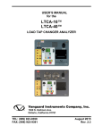
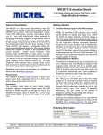
This Product Manual describes installation, operation, and servicing of UNIPOWER Sageon III Power systems. The Sageon III Power
system is available as a -48V, seven foot high system in two ratings: the 600-ampere and 1200-ampere (max). A view of the system is
provided on the cover of this manual and in Figure 1-1 (below).
FIGURE 1-1 SAGEON III POWER SYSTEM
This manual contains text of descriptions, procedures, and supporting illustrations in reference to the Sageon III Power System. It
includes the front matter and chapters 1 through 9.
1.1 PRODUCT DESCRIPTION
The Sageon III Power system is intended for Cellular, PCS, and other applications that demand stable, reliable, high current, DC
operating power. Sageon III can supply the voltage and currents shown in the following table.
PM990-8800-00, Issue 7
Sageon
Cabinet
Rack Height
Plant Output
Voltage
7-foot Tower,
Figure 1-1
7 Feet
(213.36 cm)
-48 Vdc
-48 Vdc
1-1
Plant Output
Current
(max)
600A
1200A (max)
Introduction
Sageon III Power System
As indicated above, the Power System is divided into two areas: distribution and power conversion. The system is shown in Figure 11. It provides 12 power conversion positions at 600A or 24 power conversion positions at 1200A for rectifiers and 6 distribution
groups (in 3 distribution tiers) with a user-specified quantity of AM1 circuit breakers, & GJ1 circuit breakers..
Power Conversion
Plug-in rectifier models are available in –48V. It employs modular switched-mode rectifier technology for highly efficient, low cost,
reliable operation. Each –48V rectifier can source up to 50A. The quantity of rectifiers is determined by the user to accommodate the
application. A maximum of 24 rectifiers can be installed in a unit.
Distribution
A unit can include up to 60, 5-100A AM1 circuit breakers. Up to 8, 100-450A GJ1 circuit breakers can be installed, however, each
group of 4 GJ1 type breakers reduces the available AM1 positions by 10.
Circuit breaker and fuse kits are ordered separately to accommodate the application. For AM1 type breakers, the load supply and
return connections use two-hole wire lugs for 1/4" studs (5/8" center-to-center). The supply cable is bolted to a distribution assembly
that has two 1/4-20 studs and the return connection is bolted to the return bus bar that also has 1/4" studs.
Where higher current GJ1 type breakers are specified, the load supply connection is a 3/8" ring lug bolted directly to the breaker
terminal. The return connection is bolted to the return bus bar using a two-hole lug for 3/8" bolts (1" center-to-center).
Battery Strings
Battery charge and battery return can facilitate eight sets of 2-hole lug wiring for 3/8 inch diameter studs on 1 inch centers.
Operator Panel
Mounted in the system is a modular, hot-swappable controller which includes a high-resolution 2-line digital display for monitoring of
the Sageon III Power System output current and voltage. Six push buttons are available for operating the Sageon III Power System,
selecting display information, and for changing editable parameters. A complete System configuration can be created at the operator
panel. Three System status LEDs are provided.
Communications
PC-based configuration and monitoring is available with the UNIPOWER SageView™ software. SageView is a tool to exchange
configurations and operating data between the Sageon III Power System and the PC on which SageView is running. Local PC access
is provided through a supplied USB-B connector on the front panel of the controller using the SageView software.
Remote PC access across an Ethernet network is also standard. The PC must be running SageView software and have a unique IP
address on the network. An Ethernet RJ-45 jack is provided for connecting to your company’s intranet or to the Internet. A unique IP
address is required for each Sageon III Power System. Remote access is also available via an SNMP/Ethernet board.
Alarms
Activation of customer-supplied alarm annunciators is accommodated by form-C relays. The relay state is user selectable between
normal mode (normally de-energized) and failsafe mode (Normally energized). These relays provide for external annunciation of the
alarms and are fully user configurable. Refer to SageView help for configuring these relays.
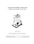
Block Diagram Description
A simplified block diagram of a 48V Sageon III Power System is shown in Figure 1-2. Single-phase or three-phase power is supplied
from the user’s AC electrical service panel.
PM990-8800-00, Issue 7
1-2
Sageon III Power System
Introduction
FIGURE 1-2 SIMPLIFIED BLOCK DIAGRAM, -48V POWER SYSTEM
PM990-8800-00, Issue 7
1-3
Introdduction
Sageon IIII Power System
m
The L
LVBD trip volttage is set using the operator panel push butttons and menuus. An LVBD bbypass switch is provided. Thhis switch
bypassses (i.e. defeatts) the SCU LV
VD in case of SCU
S
maintenan
nce, upgradingg, or failure.
Sageon III Pow
wer System opeeration can be monitored
m
at th
he operator pannel on the frontt of the Sageonn III Power Sysstem, at a PC
The S
conneected to the operator panel, or at a PC conneected to the Saageon III Poweer System over an Ethernet neetwork. The Saageon III Poweer
Systeem configuratio
on can be perfo
ormed from thee operator paneel or at a PC.
ds below distriibution area con
ntain terminalss for user connnections to alarm
m relays, batteery temperaturee compensation
n
Printeed circuit board
sensoors, communicaations, and other internal and
d external functtions. In additioon, most signaals destined for the SCU are routed first to
the BDM board or backplane
b
boarrd.
p
user access
a
to the co
onfiguration an
nd monitoring capabilities off the SCU. For security, a parrameter lock
The ooperator panel provides
featurre is included and
a PC access can require a password.
p
A PC
C that is to be cconnected to thhe Sageon III P
Power System must have the
optionnal SageView software installled and operatting.
1.2 S
SPECIFICAT
TIONS
This ssection contain
ns physical, env
vironmental, an
nd electrical sp
pecifications foor the Power syystem and its m
major assembliies.
1.2.1 Power sysstem Physical Specifications
S
Dimension
D
Width
h
Depth
h
Heigh
ht
Weigh
ht
7-fooot Tower
24.46" (62.11 cm)
21.48" (54.66 cm)
84" (213.4 ccm)
Contact the factory
Dimension
D
Width
h
Depth
h
Heigh
ht
Weigh
ht
Reectifier
8.5" (215.900 mm)
10” (254 mm
m)
1 RU
5.1 lbs (2.3 kg)
ORTANT: Th
he Power system
m is shipped without
w
Rectifieers installed. C onsequently, thhe pant is top hheavy and can topple if
IMPO
mishaandled. Refer to
t Section 2.4 Moving
M
and An
nchoring the Power system bbefore attemptinng to move thee Power system
m.
1.2.2 Power sysstem Environm
mental Specificaations
Tempperature
O
Operating .................................................. -25° to +70°C (-15° to +158°F)
Suustained Full Power
P
............................... -25° to +50°C (-15° to +122°F)
Sttorage ..................................................... -40
0° to +85°C (-4
40° to +185°F)
Shippping and Handlling
P
Power system .......................
.
................. Shiipped fully asseembled on a skkid designed too withstand thee shock and vibbration
norrmally encounttered in shippinng and handlinng
R
Rectifier Modu
ules .................................. Enccased in protecctive foam and shipped in inddividual boxes
Humiidity ........................................................ 0 to
o 95% non-con
ndensing
Note
When operating the Power System in an extremelly low humiditty environmentt (<10%), addiitional site ESD
D
n is recommen
nded. The instaallation of ESD
D conductive flooor covering oor
(Electrrostatic Dischaarge) mitigation
coatin
ng per ANSI EO
OS/ESD S7.1 and
a use of dissipative foot strraps per ANSI EOS/ESD S9.1 whenever
serviciing the equipm
ment is recomm
mended. The use of an anti-staatic wrist strap per EOS/ESD
D S1.0 Wrist
Strapss is always reco
ommended and
d is mandatory whenever servvicing the Pow
wer System in aan extremely
low hu
umidity conditiion.
PM9990-8800-00, Issue 7
1-4
Sageoon III Power System
Introduction
Altituude .......................................................... 9,800 feet (3,000m
m); Contact thee factory for deerating above sspecification
Heat Dissipation ............................................. 107
70 BTU/Hr. maaximum @ fulll load, per Recctifiers
Cooliing
D
Distribution ............................................. Con
nvection coolin
ng
R
Rectifier Modu
ules .................................. Fan
n forced air, fro
ont to back witth built-in overr temperature ppower limiting
Audibble Noise ................................................ 66d
dB for a fully lo
oaded plant peer NEBS GR-63-CORE
1.2.3 Power sysstem Electrical Specificationss
Inputt
Power Input ............................................. Seee Section 1.3.8 Rectifier Speccifications for vvoltage and cuurrent
AC P
Battery Strings ............................................... 4 maximum
m
nections ........................... 8 pairs of 3/8" stu
uds (1" center-tto-center) for 22-hole lugs
Battery String Conn
Outpuut
00A at 48 Vdc;; 1000A at 56 V
Vdc
Plant Power Outputt (max) ............................ 120
Distriibution
P
Power system, Total............................... 120
00A maximum
m
IIndividual Grou
up, AM1 ......................... 100
00A maximum
m
IIndividual Grou
up, GJ1 ........................... 120
00A maximum
m
1.2.4 General Sp
pecifications
Battery Temperaturre Compensatio
on ............. Adjjustable 0.1 to 6 mV/°C/cell
1.2.5 Bus Speciifications
Bus S
Structure Ampeerage Rating ................... Perr American Nattional Standardds Institute’s T
Telecommunicaations Protectioon
Speecifications (AN
NSI T1.311-19991) ampere taables
Chargge Bus Voltagee Drop ............................. 0.05V maximum
Dischharge Voltage Drop
D
............................... 0.25V maximum
1.2.6 EMC Speccifications
Emisssions:
Category
Harmonics
Conductted RF – AC Port
Conductted RF – DC Port
Radiated
d RF
Tested Too
IEC 6100
00-3-2; EN610
000-3-2; AS/NZ
ZS 61000-3-2
CISPR 22 (1997); EN55022 (1998); A
AS/NZS 3548 (1997)
CISPR 22 (1997
CISPR 22 (1997); EN55022 (1998); A
AS/NZS 3548 (1997)
Category
Electrostatic Dischargee
(ESD)
Radiated
d RF
Tested Too
IEC 6100
00-4-2; EN 610
000-4-2
(Air 8 kV
V, Contact 6 kV
V
IEC 6100
00-4-3; EN 610
000-4-3
(10V/m, 80-1000 MHz, 1 kHz 80% A
AM)
Hz 80% AM)
(10V/m, 1-2 GHz, 1 kH
IEC 6100
00-4-4; EN 610
000-4-4
(1 kV on
n AC lines)
(1 kV on
n DC lines)
(0.5 kV on
o signal lines – indoor)
Class
A
B
A
B
Immuunity:
Electricaal Fast Transien
nt
(EFT)
PM9990-8800-00, Issue 7
1-5
Criterion
n
A
A
A
A
Introdduction
Sageon IIII Power System
m
Immunitty continues…
Immuunity:
Category
Surge Prrotection
Tested Too
ANSI C6
62.41-1991 category B3 – AC
C lines
(Combination Wave 6 kV/3
k
kA; Ringg Wave 6 kV/500A)
00-4-5; EN 610
000-4-5: (Impuulse)
IEC 6100
(6 kV/3 kA
k Common Mode
M
[CM] on AC lines)
(6 kV/3 kA
k Differentiall Mode [DM] oon AC lines)
(0.5 kV/0
0.25 kA CM & DM on DC linnes)
Conductted RF
Voltage Dip,
Interrupttions
00-4-12; EN 61
1000-4-12: (Riing Wave)
IEC 6100
(6 kV/500A, 100 kHz CM
C & DM on A
AC lines)
(2 kV CM
M, 1 kV DM on
n DC lines)
IEC 6100
00-4-6; EN 610
000-4-6
(3V on AC,
A load and co
omms lines)
IEC 6100
00-4-11; EN 61
1000-4-11
(Level: 100% dip for 10
0 ms)
3
dip for 500
0 ms)
(Level: 30%
(Level: 100% dropout for
f 5s)
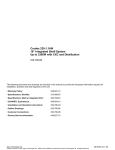
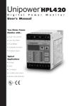
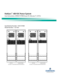
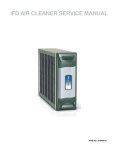
1.2.7 Rectifier Specifications
S
FIGURE 1-3 600A PL
LANT
FIGURE 1-4 1200A PL
LANT
PM9990-8800-00, Issue 7
1-6
Criterion
n
A
B
A
A
A
A
B
A
B
Sageon III Power System
Introduction
Input: 48V Rectifiers
Rated Input
Range, Nominal ..................................... 208-240 Vac
Range, Tolerance ................................... 185-275 Vac
Connection ............................................. Single phase; Phase-to-Phase or Phase-to-Neutral
Current ................................................... 13.1 @ 208 Vac; 11.3 @ 240; 16A max @ 120V or below
Frequency .............................................. 45-66 Hz
Extended Input (with output de-rating)
Low ........................................................ 85-185 Vac
High ....................................................... 275-285 Vac
Guaranteed Start ........................................... 90 Vac
Soft Start ....................................................... 8 seconds ramp-up to full load
Efficiency ...................................................... Greater than 90% @ >50% load, 230 Vac input, 25°C (77°F)
Power Factor ................................................. Greater than 0.98 at 50% to 100% of rated load
Protection
Internal Protective Devices .................... Double Fused (input)
External Protective Device .................... Thermal circuit breaker (input)
Fully Protected ....................................... 440 Vac, indefinitely
Over-Voltage Shutdown ........................ 300 Vac
Under-Voltage Shutdown ...................... 85 Vac
Service .......................................................... Hot swappable (i.e. Can be installed in or removed from an operating Sageon III Power
System)
Output, 48V Rectifiers
Float Voltage
Nominal ................................................... 54.2 Vdc
Range ...................................................... 42-58 Vdc
Equalize Voltage ........................................... 45-59.9 Vdc
Current Limit ................................................ 10% to 110% of rated output
Temperature Derating ................................... 25A @ 158°F (70°C)
Output Rectifiers
Power Limit .................................................. Foldback current limiting
Static Regulation
Line ......................................................... Better than +/-0.05%
Load ........................................................ Better than +/-0.05%
Dynamic Regulation ..................................... +/-2% for 10% to 90% to 10% step load change
+/-1% of final value within 1 ms of step change
+/-0.2% for a 25% step change in AC input voltage
Electrical Noise ............................................. <0.96 mV RMS Psophometrically weighted
Wide-Band Noise .......................................... <10 mV RMS (10 kHz-100 MHz)
Peak-to-Peak Ripple...................................... <100 mV (10 kHz-100 MHz)
Load Sharing ................................................. <+/-5% of full scale with active current sharing from SCU
Protection
Internal ................................................... Fuse
Over Current .......................................... Can sustain a short circuit at output terminals indefinitely
Temperature ........................................... Gradual reduction of power limit if heatsink temperature exceed preset limit
SCU programmable
Battery menu.......................................... Float and equalize voltages
Rectifier menu ....................................... Current limit, high and low voltage alarm limits, HVSD, and HVSD reset
PM990-8800-00, Issue 7
1-7
Introdduction
Sageon IIII Power System
m
1.2.8 Safety Speecifications
The ffollowing weree used as guidelines in the speecifications of all component s and wiring, w
with particular attention to saafety ratings
and O
OI-28 flammab
bility requiremeents.
•
U
Underwriters Laboratory
L
Stan
ndards of Safetty (UL 60950)
•
B
Bellcore Netwo
ork Equipmentt-Building Systtem (GR-1089--CORE)
1.3 A
ABBREVIAT
TIONS AND ACRONYM
MS
ABBR
REVIATION, ACRONYM
A
OR
O SYMBOL
L
ANSI
AWG
BATT
CEV
CM
DIP
EMC
EMI
ESD
FA
HVA
IEC
IEEE
LED
LSD
LVA
LVD
NEC
NEMA
PCB
RE
EC/RECT
RBOC
RFA
SBM
SSM
SCU
SMR
UBC
UL
UPS
PM9990-8800-00, Issue 7
MEANING
Americcan National Sttandards Instituute
Americcan wire gaugee
Batteryy
controllled environmeent vault
circularr mils
dual inn-line package
magnetic comppliance (or com
mpatibility)
electrom
electrom
magnetic interrference
electrosstatic dischargge
fuse annd breaker alarm
m
normallly energized hhigh voltage alaarm
Internaational Electrical Commissionn
Institutte of Electrical and Electronicc Engineers
light em
mitting diode
least siggnificant digit
low vo ltage alarm
low vo ltage disconneect
Nationaal Electric Codde
Nationaal Electrical M
Manufacturers A
Association
printedd circuit board
Rectifieer (see SMR)
Regionnal Bell Operatting Company
rectifieer failure alarm
m
Sageonn™ Battery Monnitor
Sageonn™ Site Monitoor
Sageonn™ Control Uniit
Switchh-Mode Rectifieer (see REC/R
RECT)
m Building Coode
Uniform
Underw
writers Laborattory
Uninterrruptible Poweer System
1-8
Sageoon III Power System
Introduction
1.4 R
REFERENCE
E PUBLICAT
TIONS
DOCU
UMENT
NUMB
BER
ANSI C 39.1
ANSI T1.311-1991
ANSI//IEEE C 62.411980
IEC 80
01-2
NEC 1993
1
No Nu
umber
No Nu
umber
PUB 77350
7
PE-7-1
1985
STD 487-1980
4
TR-EO
OP-000151
TR-EO
OP-000154
TR-NW
WT-000063
TR-TS
SY-000078
UL489
9
TITLE
Requiirements for Ellectrical Analoog Indicating Innstruments
DC Po
ower Systems - Telecommunnications Envirronment Protecction
IEEE Guide for Surg
ge Voltages in Low-Voltage AC Power Cirrcuits, ANSI
IEC Electromagnetic
E
c Compatibility
ty for Industriaal-Process Meaasurement and
Control Equipment, October 1987
NEC Handbook
H
199
93, National Firre Protection A
Association
OI-28
8 Standards
Centraal Office Teleccommunicationns Equipment E
Engineering Sttandards,
Decem
mber 1984
U S West
W Telecomm
munications Eqquipment Installlation & Remooval Guidelinees,
May 1990
1
Comm
munications Ty
ype Battery Chhargers, NEMA
A/ANSI
IEEE Guide For Thee Protection off Wire-Line Coommunicationss Facilities
ng Electrical Power Stations
Servin
Bellco
ore Generic Reequirements forr 24-, 48-, 1300-, & 140-Volt Central Officee
Powerr system Rectiffiers, May 19885
Bellco
ore Generic Reequirements forr 24-, 48-, 1300-, & 140-Volt Central Officee
Powerr system Contrrol and Distribuution, May 19885
Bellco
ore Network Equipment-Buillding System G
Generic Equipm
ment
Requiirements, Issuee 4, July 1991
Bellco
ore Generic Ph
hysical Design Requirements for Telecomm
munication
Produ
ucts and Equipm
ment
UL Molded
M
Case Ciircuit Breaker E
Enclosures, Maay 1984
1.4.1 Monitoring Specifications
Operaator panel voltaage and curren
nt ............... 2-liine digital disp
play
Operaator panel accu
uracy
V
Voltage accuracy ................................... 0.50% +/- least significant digit
C
Current accuraccy .................................... 1%
%
Systeem status.................................................. Greeen, yellow, an
nd red LEDs
Locall Communicatiions ................................. USB (SageView required)
r
Remoote Communications .............................. Eth
hernet/SNMP
1.4.2 Alarm Speciffications
Each of following alarms
a
is annun
nciated by a lig
ghted LED on the
t operator paanel and by a reelay state channge. Relay conttact output
n the distributio
on.
terminnals are on thee alarm PCB in
nunciation
A. Usser Alarm Ann
Five uuser programm
mable relays. One
O form C con
ntacts rated 1A resistive @ 244Vdc, 0.5A ressistive @ 48Vddc.
P
B. Reectifier Front Panel
Threee status LEDs (Green,
(
Amberr, and Red) aree located on thee Rectifier fronnt panel.
T
C. Baattery Current Temperature
Battery Temperaturre Sensor Inputt ................ Com
mpensation and alarm annun ciation, 1ambiient, 1-4 batteryy
4 battery stringss; accuracy 1%
%
Battery Current Traansducer Input ................. 1-4
ype
User connections ............................................ No. 6 screw termiinals; lugless ccompression typ
M
D. Saageon Battery Monitor
Battery strings ................................................ 4 maximum
m
PM9990-8800-00, Issue 7
1-9
Introduction
Sageon III Power System
Battery voltage .............................................. 75V maximum
Cells (single cell or monoblock) ................... 24 maximum per SBM board
Cell voltage ................................................... 2V, 4V, 6V or 12V (maximum input 3.33V, 6.66V, 10V, and 20V respectively)
Accuracy ....................................................... +/-10mV at 0°C to 40°C
Resolution ..................................................... 5mV per cell (2V, 4V, and 6V ranges)
10mV per cell (12V range)
Sampling interval .......................................... 1-60 minutes
SBM boards .................................................. 4 maximum
Interconnection ............................................. 16-conductor ribbon cable; 30 feet (10m) maximum length
E. Site Monitor
Analog inputs ................................................ 8
Signal range .................................................. 0-5V
Input protection ............................................. Over-voltage and reverse polarity
Signal scaling and alarm levels ..................... Scale factor and low and high alarm thresholds are user programmable at operator panel
Digital inputs................................................. 12
Signal source ................................................. Voltage free contacts
Logic of digital input .................................... User defined from operator panel
Control outputs ............................................. 4
Output signal source
Voltage free form C relay contact; 1A @ 30 Vdc
1.5 PRODUCT SUPPORT
Product support can be obtained using the following addresses and telephone numbers.
UNIPOWER, LLC
65 Industrial Park Road
Dunlap, TN 37327
Customer Service, Voice: (800) 440-3504
Customer Service, Fax: (423) 949-3647
Field Service: (800) 299-3907
Web site –
http://www.unipowerco.com
When contacting UNIPOWER, please be prepared to provide:
1. The Power system part number and serial number - see the equipment nameplate
2. Your company’s name and address
3. Your name and title
4. The reason for the contact
5. If there is a problem with Power system operation:
•
Is the problem intermittent or continuous?
•
What actions were being performed prior to the appearance of the problem?
•
What actions have been taken since the problem occurred?
PM990-8800-00, Issue 7
1-10
Sageoon III Power System
Installation
2.0 INSTALLA
ATION
This cchapter describ
bes installing a Sageon™ III Power
P
system. If questions orr problems arisse during installlation, please rrefer to Section
n
1.6 Prroduct Supportt and contact a UNIPOWER Field Service technician
t
for aassistance.
Power system is
i factory assem
mbled and testeed. GJ1 circuit breakers speciified on the ordder are factoryy installed. AM
M1 circuit
The P
breakkers specified on
o the order aree shipped in protective packaaging for on-sitte installation. R
Rectifiers speccified on the orrder are
shippped in separate,, protective pacckages for on-ssite installation
n.
Power system is
i designed for top-entry of distribution and
d battery cablinng. AC input caabling can enteer the plant throough any lower
The P
side/rrear panels or through
t
the botttom of the plan
nt when the plaant is located oon an elevated floor. All cablling is user-suppplied.
WARNING
Electrical shock
k hazard
Hazardous voltage
e can cause death
d
or serio
ous injury.
ove power fro
om all wires and terminals before workin
ng on equipment.
Remo
ORTANT: All wiring must meet
m the National Electrical Code
C
and otherr applicable inddustry and locaal codes.
IMPO
Breaker/Fuse Layout
L
label on
n the inside of the
t door to the distribution arrea lists all disttribution positiions. The label provides spacee
The B
for yoou to write breaaker/fuse curreent rating and part
p number. Label entries shhould be complleted before beginning the insstallation to
help eensure that the correct breakeer/fuse is insertted in each possition.
A
Rectiifier Position Address
que, sequential address withinn the Sageon IIII Power System
m. The System
m operator uses
Each rectifier positiion is factory-aassigned a uniq
d operating the System to iden
ntify and accesss a specific Reectifier. The A
AC Backplane bboard at each
this aaddress when configuring and
rectiffier position has one DIP swittch on which th
he address is seet. See the illusstration below..
ORTANT: Do
o not change th
he factory-set switches. If inad
dvertently channged, go to Section 6.6 for a procedure to set the
IMPO
switches to the prop
per address.
ning the Distriibution Area Door
D
Open
t distribution
n area door to iinstall load suppply and returnn cables, batteryy cables, and
Durinng installation, it will be neceessary to open the
alarm
m wires. Lift th
he paddle surro
ounding the key
y lock, rotate itt 90 degrees, annd open the dooor. Keys are tiied just inside tthe door.
2.1 IINSTALLAT
TION SUMMARY
A typpical installatio
on sequence is provided
p
below
w. References to
t appropriate sections in thiss manual are inncluded.
1.
R
Review the list of user-supplied tools and acccessories in Section 2.2.
2.
S
Select a locatio
on for the Poweer system. See Section 2.3.
3.
S
Select battery, AC
A input, and distribution wiire sizes based
d on current andd length of runn. See Section 22.2.
PM9990-8800-00, Issue 7
2-1
Installlation
Sageon IIII Power System
m
4.
M
Move the Poweer system and accompanying
a
assemblies to the selected loocation. Anchorr the Power syystem to the flooor. See Section
n
22.4.
5.
IInstall AC inpu
ut wiring betweeen the user’s AC
A electrical service panel annd the Power ssystem. See Secction 2.5.
6. C
Connect the AC
C input wiring to AC terminaals in bottom seection. See Secction 2.5.4.
7. IInstall battery cabling.
c
See Seection 2.6.
8. R
Route and conn
nect supply and
d return cabling
g to customer’s loads. See Seection 2.7.
9. C
Connect extern
nal alarm annun
nciators. See Seection 2.8.
10. IInput/Connect options:
o
Batterry Temperaturee Sensors, Batttery Current Trransducers, Saggeon Battery M
Monitor, Site M
Monitor, and
ccommunication
ns (SNMP). See Sections 2.9 through 2.13.
11. IInstall Rectifierrs. See Sectionn 2.14.
12. C
Commission th
he plant. See Ch
hapter 3 Comm
missioning and Chapter 4 Connfiguration andd Operation.
2.2 R
REFERENCE
E MATERIAL
L
This ssection contain
ns lists, tables, and methods th
hat are referenced in subsequuent procedures. Three subsecctions comprisse the
Referrence Material section.
•
T
Tools and Acceessories – Read
d the included list for a previeew of the user--supplied itemss that will be reeferenced durinng the
innstallation and
d servicing proccedures.
•
S
Selecting and Sizing
S
DC Pow
wer Cables – Prroper cable siziing is critical too system perfoormance. This ssection providees a formula
aand table that simplify cable selection.
s
•
T
Torque Specificcations – The torque
t
specificcation table in this
t subsectionn is referenced iin procedures tthat include haardware.
2.2.1 Tools And
d Accessories
To innstall the Sageo
on III Power sy
ystem, the follo
owing user-sup
pplied items shoould be availabble.
•
E
Equipment to move
m
Power sy
ystem to installaation site
•
F
Floor anchors to
t secure the Po
ower system
•
C
Conduit and/orr overhead wiree racks for cablling
•
S
Standard insulaated installation
n tools (e.g. haand tools, sockeet set, cable cuutters, cable inssulation strippeers)
•
T
Torque wrench
h to ensure corrrect tightening of hardware; see
s Table 2-2 fo
for torque speciifications
•
E
Electrical service panel circuiit breakers
•
D
Digital Voltmeter with: 4-1/2 digit display
•
C
Cables and lugss; appropriate crimping
c
tools:
AM1 Circu
uit Breaker Disstribution uses Two-hole lugss for 1/4" threaaded studs (5/88" center-to-cennter) and GJ1 C
Circuit Breakerr
Distributio
on uses Single hole
h lugs for 3//8" bolt.
Return buss uses Two-holle lugs for 1/4" threaded studss (5/8" a centerr-to-center) annd two-hole luggs for 3/8" threaded studs (1"
center-to-ccenter).
Battery Ch
harge and Disch
harge Buses usse Two-hole lu
ugs for 3/8" threeaded studs (1" center-to-cennter).
•
C
Conduit, condu
uit connectors, and conduit beending tools
•
A
Anti-Static Serv
vice Kit with static
s
dissipativ
ve mat and wrisst strap for hanndling electronnic circuit boardds (e.g. Interface Board)
((available from
m electronic sup
pply sources)
PM9990-8800-00, Issue 7
2-2
Sageoon III Power System
Installation
2.2.2 Selecting and Sizing DC
C Power Cabless
Protective circuits, overall
o
system performance, and safety dep
pend on the prooper sizing of D
DC cables for ccurrent and accceptable DC
m
size allowable is th
he larger of the wire size per tthe National Ellectrical Code or the calculatted wire size.
voltagge drop. The minimum
m
to deterrmine the wire size.
Use thhe following method
1. C
Calculate the minimum
m
area in
i circular milss (CM) required
d for copper w
wire using the fo
following formuula:
22
2.2 x I x L
CM =
V
where:
c
mils in
n the cable
CM = miniimum area of circular
I = maximu
um current (in amps)
L = one-waay cable length
h (in feet)
V = allowaable loop voltage drop (in vollts)
Example: Assume
A
a maximum output current
c
of 100 amperes,
a
an alllowable loop vvoltage drop off 0.25 volts, and a distance off
50 feet between the Poweer system and the
t load.
I = 100 am
mperes
L = 50 feett
V = 0.25 volts
v
(2
22.2)(100)(50)
CM =
(0.25)
CM = 440,,000 circular mils
m
2.
A
After calculatin
ng the minimum
m area in circu
ular mils, selectt the proper coppper wire size from Table 2-1; always chooosing the next
laarger wire sizee if the area ratiing falls betweeen values. Forr the above exaample, select 5500 MCM wiree.
3.
D
Determine the minimum
m
wiree size for ampacity according to the code auuthority havingg jurisdiction inn your locationn.
4.
S
Select the largeer of the sizes calculated
c
for voltage
v
drop orr ampacity.
TABLE 2-1
2 WIRE SIZ
ZING
SIZE
AWG
NO.
AREA
IN CM
14
12
10
8
6
4
2
1/0
2/0
4/0
M
350 MCM
500 MCM
M
750 MCM
M
4,110
6,530
10,380
16,510
26,250
41,740
66,370
105,500
133,100
211,600
350,000
500,000
750,000
CURRENT
G
CARRYING
CAPACITY
Y*
OPE
NCLOSE
EN
D
N
AIR
15
15
20
20
30
30
45
45
70
65
100
85
5
135
115
150
0
185
175
5
210
230
0
300
310
0
425
380
0
525
475
5
660
A
DIA
BA
ARE
CO
OND
INC
CHES
W DIA
RHW
OV
VER INS
CHES
INC
0.0064
0.0081
0.1 02
0.1 46
0.1 84
0.2232
0.2292
0.3373
0.4418
0.5528
0.6681
0.8814
0.9998
0.199
0.211
0.244
0.311
0.400
0.455
0.511
0.633
0.688
0.788
0.988
1.122
1.344
EC Handbook 2011,
2
Table 310-17 adjusted for 50°C (122°°F) ambient tem
mperature.
* Datta based on NE
PM9990-8800-00, Issue 7
2-3
HW
RH
BEN
ND
RA
ADIU
S
CHE
INC
S
0.95
1.05
1.200
1.55
2.000
2.25
2.55
3.15
3.400
3.900
4.900
5.600
6.700
Installlation
Sageon IIII Power System
m
2.2.3 Torque Sp
pecifications
Propeer plant perform
mance requiress that the hardw
ware employed
d during installaation be tightenned securely but not over tighhtened. Use a
torquue wrench to en
nsure that hardw
ware is tighten
ned to the speciification providded in Table 2--2.
TA
ABLE 2-2 TO
ORQUE SPEC
CIFICATION
NS, STEEL FA
ASTENERS
Inch/Pound
s
4.5
5.4
9.0
10.8
17.1
18.0
24.3
27.9
59.4
70.2
118.8
129.6
216.0
248.4
324.0
378.0
540.0
594.0
756.0
864.0
Bolt Size
4-40
4-48
6-32
6-40
8-32
8-36
10-24
10-32
1/4-20
1/4-28
5/16-18
5/16-24
3/8-16
3/8-24
7/16-14
7/16-20
1/2-13
1/2-20
9/16-12
9/16-18
Foot/Poun
nd
s
0.375
0.450
0.750
0.900
1.425
1.500
0.025
2.325
4.950
5.850
9.9
10.8
18.0
20.7
27.0
31.5
45.0
49.5
63.0
72.0
NewtoonMeteers
0.51
0.61
1.022
1.222
1.933
2.033
2.755
3.155
6.71
7.933
13.442
14.664
24.440
28.007
36.661
42.771
61.001
67.111
85.442
98.662
2.3 S
SELECTING
G A LOCATIO
ON
Installl the Power sy
ystem in a locattion that provid
des the followiing.
•
A
Access to a sou
urce of reliable, stable, electriically clean AC
C power
•
A dry, well ven
ntilated room th
hat meets the conditions
c
stateed in Section 1 .2.2 Power sysstem Environm
mental Specificaations
•
S
Sufficient accesss for plant insstallation and servicing (refer to NEC and loocal codes)
•
S
Sufficient ceilin
ng height to peermit use of overhead cable trrays and conduuit for AC inpuut cables and D
DC load supply and return
ccables
•
A level, flat flo
oor capable of supporting
s
the weight of the Power
P
system and accepting bolts or other uuser-supplied hhardware to
ssecurely anchorr the plant
•
A pest and varm
mint free area
2.4 M
MOVING AN
ND ANCHOR
RING THE POWER SYST
TEM
WARNING
Tip Over/Cru
ush Hazard
er system tip over
o
can caus
se death or se
erious injury.
Powe
Keep the Power sy
ystem vertical.
er system is heavy and also
o top heavy. Use a forklift or other equipment to movve
Powe
or transport the Po
ower system.
PM9990-8800-00, Issue 7
2-4
Sageon III Power System
Installation
The Power system is heavy (up to 1,000 lbs (453 kg)) and it is top heavy. An improperly handled Power system can topple. Proper
handling equipment is required to transport the plant. The unit dimensions are given in Figure 2-1. Figure 2-2 shows the Power system
base and the floor mounting hole pattern.
Floor Mounting: The Power system must be permanently anchored. Install one anchor in each floor corner. Mounting slots are
provided in each corner to allow for ease of anchoring. Mark and drill holes where shown in Figure 2-2. UNIPOWER offers several
seismic zone hardware kits.
Caution: Do not block rear panel grille. A blocked grille will limit the flow of cooling air and can
result in equipment overheating and failure. Minimum clearance behind and to the sides of the
plant must be 2" (5 cm).
FIGURE 2-1 POWER SYSTEM DIMENSIONS
PM990-8800-00, Issue 7
2-5
Installation
Sageon III Power System
FIGURE 2-2 PLANT BASE
Caution: Do not block rear panel grille. A blocked grille will limit the flow of cooling air and can result in equipment
overheating and failure. Minimum clearance behind the Plant is 2" (5 cm).
To move and mechanically secure the Power system:
1. Prepare the installation site. Install floor anchors (see Figure 2-2 for mounting pattern) as needed.
2. Carefully transport the Power system to the installation site. If possible, protective wrapping should remain in place until the
move is completed.
•
Since the plant is shipped bolted to a skid, a forklift is typically used for transport to the installation site.
•
A lift point is provided in each rack corner, near the top, for an overhead crane or other lifting equipment.
•
Be careful not to bend or otherwise damage the side and rear panels.
•
Be careful not to mar or otherwise damage the front bezels.
3. Set the Power system in place.
4. Securely fasten the Power system to the floor.
2.5 CONNECTING AC POWER TO THE POWER SYSTEM
Connect single-phase power, through a circuit breaker, to each input in plant. See Section 1.2.7 Rectifier Specifications for voltage
and current requirements. See section 3.4 for more on connections.
Single-Phase AC
Power to Power
System
User’s AC Electrical
Service Panel
A ground is required with the AC power connections for safety and for limiting EMI/RFI emissions.
PM990-8800-00, Issue 7
2-6
Sageoon III Power System
Installation
Plantt Rack:
s
rack to the site’s centrral frame groun
nd applicable inn accordance w
with codes andd the customer’’s standard
Grounnd the Power system
practiice. Unthreaded holes for bollting an earth/safety ground wire
w to the rackk are provided in the top and bottom, both oon rear.
Remoove the paint frrom a small areea (e.g. 1.5 in/3
3.8 cm diameteer) around the sselected holes and through-bolt the ground wire lug to thee
rack.
Returrn Bus:
Connnect the plant reeturn bus to thee site’s central office ground. Select a cablee size applicablle in accordancce with codes aand the
customer’s standard
d practice. The minimum cable size must bee capable of car
arrying the faullt current from any installed ddevice. Since
nnection, securee the wire lug to
t a 3/8" stud oon the return buus (battery) or bolt the wire luug to 3/8"
this iss typically a high current con
throuugh hole on the return bus (loaads). The returrn buses within
n the plant are eelectrically connnected. See Fiigure 2-3 for bus locations.
FIG
GURE 2-3 RETURN BUS L
LOCATIONS
2.5.1 Lightning and Transient Suppression
Rectifiers contain basic transient suppression
s
in the form of Metal Oxide Varristors (MOVs)). MOVs are innstalled from L
L1 to L2, L1 to
om line transiennts in an indusstrial environm
ment according to ANSI
earth,, and L2 to eartth. They are siized to providee protection fro
C62.441-1991 for Cllass B3 equipm
ment and IEC 61000-4-5.
nsient protection is needed in a more severe environment w
with, for exampple, a high inciidence of lightnning strikes
Suppllementary tran
(indirrect or direct) and/or
a
severe switching transients beyond th
he levels indicaated in the aboove standards. Install higher rrated
supprression devicess to the AC electrical service where approprriate.
2.5.2 User's AC
C Electrical Serrvice Panel
The A
AC electrical seervice panel an
nd wiring from
m the service paanel to the Pow
wer system is suupplied by the user.
1. E
Electrical shock
k hazard – Rem
move power fro
om all involved
d wires and terrminals before proceeding.
2. D
Determine the number
n
of AC breaker positio
ons needed. Alllow one breakker position forr each Rectifierr to be installedd in the Power
ssystem. Alternaatively, up to tw
wo Rectifiers can
c be fed from
m one breaker pprovided the brreaker and wiriing meet local and national
eelectrical code requirements. Power system terminals will accept 6-12 A
AWG (13.6-3.3 mm2).
3. R
Run the needed
d quantity of AC
A power cablees from the serv
vice panel to thhe Power systeem.
PM9990-8800-00, Issue 7
2-7
Installlation
Sageon IIII Power System
m
L
Label each breaaker position and
a both ends of
o each AC pow
wer cable with the Power sysstem number annd rectifier possition address
too which it willl be connected (e.g. P1R1 = Power
P
system 1,
1 Rectifier possition address 11). Rectifier poositions are num
mbered from
toop to bottom as
a shown below
w.
Rectifier 1
Rectifier 3
↓
↓
Rectifier “n-1””
Reectifier
Section
Recttifier 2
Recttifier 4
↓
↓
Recti fier “n”
4. A
At each breakerr position in th
he AC panel, in
nstall a delayed
d-trip circuit brreaker for eachh cable. Refer too Table 2-3 forr breaker
rrecommendatio
on.
5. E
Ensure that all circuit breakerrs are in the Offf position.
6. C
Connect the power cables to the
t service pan
nel.
TABLE
T
2-3 CIRCUIT
C
BRE
EAKER SELE
ECTION, AC
C POWER
Rectifiers
R
Poweered
1
2
Breaaker Rating
20A
40A
2.5.3 AC Cablin
ng
This ssection describ
bes connecting the AC input cables
c
within th
he Power systeem. An AC inpput cable can ennter the plant sseveral ways:
•
T
Through either the lower secttion side panel or lower rear panel
p
of the cabbinet.
•
U
Upward throug
gh the open basse of the rack.
A termination block located in the lower seection of the unnit.
For each ordered Reectifier, connecct an AC input cable to the AC
ORTANT: Do
o not change th
he factory-set reectifier position address. Thee address is set on the AC Bacckplane board..
IMPO
Syste
em Wiring
L1 L2
RECT 1
L1 L2
RECT 1
L1 L2
RECT 2
L1 L2
L
REC
CT 3
L1 L2
RECT 4
L1 L2
RECT 5
L1 L2
RECT 6
L1 L2
RE
ECT 7
L1 L2
RECT 8
L1 L2
RECT 9
L1 L2
L1
L L2
L1 L2
RECT 10
RECT
R
11
RECT 12
Line1
1
Line2
2
Ground
d
er Wiring
Use
AC Ca
able from U
User's
AC Ele
ectrical Serrvice
Panel
FIGUR
RE 2-4 AC INP
PUT CABLIN
NG WITH RE
ECTIFIER ON
N/OFF OPTIO
ON
PM9990-8800-00, Issue 7
2-8
Sageon III Power System
Installation
2.6 CONNECTING BATTERY CABLES
Routing the stiff, heavy gauge battery cables is difficult. Two people may be needed. Exercise extreme caution to avoid a short
circuit across the battery terminals.
WARNING
Arcing hazard
Arcing can cause equipment damage, load interruptions, and personal injury.
Remove watch and jewelry. Use insulated tools and extreme caution when
working with a battery string.
Carefully insulate unterminated battery cable ends.
At the Power system, battery cables connect to the battery charge bus and return bus. Three battery charge and battery return bus
options are available to facilitate 2-hole lug wiring: 3/8 inch diameter studs on 1 inch centers for a single tier, 3/8 inch diameter studs
on 1.75 inch centers for a single tier and 3/8 inch diameter studs on 1.75 inch centers for three tiers.
Installing the Battery Cables:
This procedure includes the installation of up to four optional battery current transducers. Transducer mounting and wiring
information is found in Section 2.10. Ignore references to transducers in the following procedure if not part of your installation.
If the installation includes a battery disconnect switch, modify the procedure accordingly.
1. Determine the correct battery cable size and shortest cable run. See Section 2.2.2 Selecting and Sizing DC Power Cables. The top
of the distribution section is open for easy access when routing battery cables between the battery string and the Power system
battery charge bus and return bus. See Figure 2-5 for the location of the battery charge bus and battery return bus within the plant.
2. Mount the optional battery current transducer(s) and connect the transducer cable(s) between the transducer and the Power system
as indicated in Section 2.10. Be sure that a transducer’s battery cable opening is large enough for the selected cable diameter and
the number of cables.
3. Run cables between the plant and battery string 1. Route either battery cable (+ or -) through the optional battery current
transducer; all battery cables routed through a transducer must be the same polarity. Transducers are marked, typically with an
arrow, to indicate current direction. (See section 2.10)
FIGURE 2-5 BATTERY CHARGE BUS AND BATTERY RETURN BUS LOCATIONS
PM990-8800-00, Issue 7
2-9
Installation
Sageon III Power System
4. At the Power system, install appropriate lugs on cables.
CAUTION
a)
Secure the negative cable to the battery charge bus.
b) Secure the positive cable to the battery return bus.
NOTE: See table 2-2 for torque specifications.
5. At the battery string, appropriate battery lugs/terminals/clamps. Confirm polarity and connect the wires to the battery string
terminals.
6. Repeat the above steps for each battery string to be connected.
2.7 CONNECTING CUSTOMER LOADS
Supply and return cables are connected between customer loads and Power system distribution. Interconnecting cables and lugs are
supplied by the user. Refer to Section 2.2.1 Tools and Accessories for lug requirements. Refer to Section 2.2.2 Selecting and Sizing
DC Power Cables for cable sizing.
Note: To field install additional distribution refer to Chapter 7 Distribution Option Kit Installation. To field install additional fuses or
circuit breakers in the present distribution refer to Chapter 8 Circuit Breaker and Fuse Kit Installation.
Route supply and return cables from the Power system to the loads in overhead racks or cable trays. The plant cables drop from the
overhead racks through the open top of the plant.
Connect the return cables to the return bus (loads), the vertical bus to the right side of the distribution area. Connect the supply cables
to either a distribution assembly (for AM1 type breakers) or a GJ1 type breaker output terminal. A typical load connection is shown in
Figure 2-6.
Note: Other tiers and groups are cabled similarly. Connect all load returns to the return bus.
FIGURE 2-6 LOAD SUPPLY AND RETURN CABLING
PM990-8800-00, Issue 7
2-10
Sageon III Power System
Installation
Distribution is organized by Tier (1-3), Group (A & B) and position (1-10). See Figure 2-7. The Breaker/Fuse Layout label on the rear
of the distribution area door is for recording breaker/fuse current rating and part number.
BATTERY
DISCHARGE
BUS
DISTRIBUTION
GROUPS A & B
ON EACH TIER
LEFT SIDE
FIGURE 2-7 DISTRIBUTION GROUP IDENTITIES AND LOCATIONS
Distribution Group Orientation:
Orientation of a group determines the routing of the supply cables. Figure 2-8 shows the orientation of AM1 distribution assemblies,
using their output studs (circled) as points of reference. Groups A & B are always oriented as shown.
FIGURE 2-8 DISTRIBUTION AREA, TOP VIEW, AM1 TYPE BREAKER DIST. SHOWN
PM990-8800-00, Issue 7
2-11
Installlation
Sageon IIII Power System
m
2.7.1 Load Retu
urn Cables
Term
minate all load return
r
cables att the return buss (loads) shown
n in Figure 2-66. This bus is loocated on the riight of the disttribution area
and cconsists of up to
o three verticallly mounted plates. The platees have pairs off 1/4" and 3/8" threaded studs for 2-hole luggging. Use the
h AM1 type breeakers. The 3/88" studs are forr higher currennt loads protected by GJ1 typee
1/4" sstuds for lowerr current loads protected with
breakkers.
2.7.2 Load Supp
ply Cables, AM
M1 Type Break
ker Distribution
n
Distribu
ution
Cabliing
Tier 3
Group A
G
Tier 3
Group B
Tier 2
Group
G
A
Tier 2
Group B
Tier 1
Group A
G
Tier 1
Group B
Left Rear Corner of Rack
Left Front Corner of Rack
Connnect customer lo
oad supply cab
bling in order by
b Tier, Group,, and position nnumber as show
wn on the Breaaker/Fuse Layoout label on thee
insidee of the distribu
ution area doorr. Cables are ro
outed toward th
he nearest rackk corner and then upward, as shown in Figuure 2-9.
Fuse Ala
arm
(FA) Wire
CD00031a
Distribution
Assemb
blies
Bus Barss
Distributiion, Rack Left Side
FIGUR
RE 2-9 DISTRIIBUTION CA
ABLE ROUTIING
PM9990-8800-00, Issue 7
2-12
Sageon III Power System
1.
2.
Installation
Select a starting point, Tier 1, Group A Position 1 is recommended. Use appropriate lugs on the load supply and return
cables.
Dress the cable as shown in Figure 2-9, toward the front or rear of the rack according to the orientation of the distribution
assembly. Dress the cable away from rack assembly hardware to avoid possible chafing of the cable insulation.
Battery Discharge Bus Bar
Distribution Assembly
Alarm Strip
Mounting Bracket
Holes for
Securing Cable
Paired Output Studs
Circuit Breaker or Fuse –
Note orientation:
Short Mounting Surface
Long Mounting Surface
(Output Terminal)
Load Supply Cable,
See Detail Below
Alarm Connection
Bus Bar
Circuit Breaker or Fuse –
Note mounting surface
orientation.
Load Supply Cable and
2-Hole Lug
1/4-20 Nuts
Detail of Load Supply Cable Connection
FIGURE 2-10 AM1 TYPE DISTRIBUTION LUGGING
3.
4.
5.
6.
Move to Group A, Position 2 and repeat the above steps. Repeat the steps until all positions in Tier 1, Group A are cabled.
Move to Tier 1, Group B, and cable the positions.
Perform the above steps for Tiers 2 and 3.
Bundle and secure cables as follows. Two cable-securing tabs are provided in each distribution assembly mounting bracket.
See Figures 2-10 and 7-2 for cable securing locations
1) All Group A – Bundle cabling from all tiers at the left front of the rack.
2) All Group B – Bundle cabling from all tiers at the left rear of the rack.
PM990-8800-00, Issue 7
2-13
Installlation
Sageon IIII Power System
m
2.7.3 Load Supp
ply Cables, GJJ1 Type Breakeer Distribution
Whenn ordered, GJ1 type distributiion assemblies are always thee upper-most ddistribution asseemblies in a pllant since no m
more
distribbution can be installed
i
abovee a GJ1 type asssembly. Cablee routing and coonnection are sshown in Figurre 2-12. Conneect the top
breakker terminals to
o user loads. Th
he bottom breaaker terminals are
a bolted to thhe battery dischharge bus at the factory.
Distrib
bution Assembliess
Tier 3, Grp
G A
Tier 3, Grp B
Fuse Alarm
m
(FA) Wire
e
Fuse
e Alarm
(FA
A) Wire
Tier 2
Group A
Tier 2
Group B
Tier 1
Group A
Tier 1
Group B
Bus Ba
ars
Left Rear Corner of Rack
Left Front Corner of Rack
Distribution
Assembliies
FIGURE 2-11
2
GJ1 TYP
PE BREAKER
R DISTRIBUT
TION ASSEM
MBLIES, TYP
PICAL
1.
S
Select a starting
g point, the low
west Group lettter, Position 1 is
i recommendeed.
2.
F
For the load sup
pply cable end
d, use a single-h
hole lug for a 3/8"
3 bolt. See F
Figure 2-12.
3.
B
Bolt the supply
y cable end to th
he breaker term
minal using 3/8
8" hardware peer figure 2-12.
4.
R
Repeat the abov
ve steps for eacch GJ1 type brreaker in the Grroup
5.
R
Repeat the abov
ve steps for eacch GJ1 type brreaker group.
Load Supply Cable
e with 3/8 Lug
and Output Terminal Hardware
GJ1
1 Circuit Brea
aker, 4 Places
3/8 Nut and Flat Washer
Bra
acket Mounting
g Screw
12-2
24 x 3/4, 2 Pla
aces
Mou
unting Bracket, U-Shaped
x Bolt
3/8 x 1 Hex
Bevel Washer
Flat Wa
asher
Brea
aker Mounting
g Bar, 2 Place
es
Bus Bar, L-Shaped
Breaker Input T
Terminal Hard
dware
FIIGURE 2-12 GJ1 TYPE BR
REAKER DIS
STRIBUTION
N WIRING
PM9990-8800-00, Issue 7
2-14
Sageon III Power System
Installation
2.8 CONNECTING EXTERNAL ALARM ANNUNCIATORS
Five form C relay contact outputs are available for connection to external, user-supplied alarm annunciators. Figure 2-13 shows the
Interface Board and the row of connectors (X6) provided for these connections. Review the alarm and relay contact specifications in
Section 1.2.11 Alarm Specifications to ensure compatibility with external annunciators and other equipment before proceeding.
Alarm relay outputs are provided for remote annunciation of fault conditions. All relays are user programmable through the SageView
software.
As shown in Figure 2-13, each relay has three connections: common, normally open, and normally closed. The normally open (NO)
and normally closed (NC) labels are for an un-powered Sageon III Power System. Relay coils are energized during normal Sageon III
Power System operation. During an alarm, the appropriate relay coil is de-energized.
IMPORTANT: When the relay contacts are connected to a reactive load, such as a solenoid or relay coil, the load must be shunted by
a transient suppression device to prevent damaging relay contacts.
FIGURE 2-13 INTERFACE BOARD, CUSTOMER ALARM CONNECTIONS
2.9 BATTERY TEMPERATURE SENSORS AND KITS (OPTION)
The Multiple Battery Temperature Board is included in the Sageon III distribution. It can accommodate up to four battery temperature
sensors. Temperature sensors are ordered separately. If ordered with the system, the sensors are connected to the Multiple Battery
Temp Board and the sensors and wires then coiled and tied to the return bus.
If not ordered with the Sageon III Power System, an Ambient and up to four Battery Temperature Sensor can be ordered separately.
Installing the Sensors:
Open the distribution door and locate the Multiple Battery Temperature Board. Locate the coiled sensors.
1. If not already connected, plug the battery temperature sensor connectors and the ambient temperature sensor into the Controller
backplane board. See Table 2-4 for the connectors. The connectors are keyed.
TABLE 2-4 BATTERY TEMPERATURE SENSOR CONNECTIONS
Sensor
PM990-8800-00, Issue 7
Connector
Battery String 1 Temperature
X1 in Figure 2-19
Battery String 2 Temperature
X2 in Figure 2-19
Battery String 3 Temperature
X3 in Figure 2-19
Battery String 4 Temperature
X4 in Figure 2-19
Ambient Temperature
X3 in Figure 2-18
2-15
Installation
Sageon III Power System
2. Select a location for mounting the ambient temperature sensor ring lug. The temperature of this mass should have a fairly long
thermal time constant (e.g. temperature should not cycle with short-term temperature changes due to normal environmental
heating and cooling cycles). Typically this could be a nearby equipment rack the Sageon III system is mounted adjacent to.
3. Fasten the ambient temperature sensor to the selected point using appropriate user-supply hardware.
4. Route the 4 battery temperature sensors to the battery string(s). Typically somewhere close to the string midpoint.
5. Determine which battery posts will have sensors attached. Suggested location is shown in the battery string drawing, figure 2-14.
Note: The highest of the four battery temperature readings is used for compensation. Locate a sensor at the warmest battery,
generally one at the center of a battery group.
6. Determine the charge/discharge status of the battery string. Connecting the sensors may result in a momentary battery string open
circuit when the terminal bolt is removed.
CAUTION: DO NOT proceed if the battery string is being charged or discharged at a high rate. Continue only when the charge
or discharge rate is at a safe level.
7. Remove the bolt holding the inter-cell battery strap in place. Insert the bolt through the battery temperature sensor ring lug,
through the strap, and into the battery terminal. Tighten the bolt as recommended by the battery manufacturer.
8. Repeat steps 6 and 7 to install the remaining battery temperature sensors.
9. Bundle and secure excess wiring.
10. Enable compensation using the operator panel push buttons and menus or a PC running SageView.
11. If installing the Sensor Kit, get the compensation chart label. Remove the backing from the label and place the label on the inside
of the distribution area door.
+
+
+
+
+
+
+
+
+
+
+
+
+
+
+
+
+
+
CD00036a
Temperature
Sensor 1
+
+
+
+
+
+
FIGURE 2-14 TEMPERATURE SENSOR LOCATION
2.10 INSTALLING A BATTERY CURRENT TRANSDUCER (OPTION)
The optional battery current transducer senses the battery current for display on the operator panel. When installed, the battery current
transducer also allows the user to configure the SCU to limit the recharge current to the battery string in order to extend battery life;
and set a fixed, repeatable discharge current for battery discharge tests.
Install one battery current transducer per battery string (up to four transducers). If not ordered with the Sageon III Power System, a
Battery Current Transducer Kit is available.
PM990-8800-00, Issue 7
2-16
Sageon III Power System
Installation
To install a transducer kit:
1
Mount the transducer(s) with user-supplied hardware. Figure 2-15 shows a typical transducer. Often, transducers are mounted on
the battery rack. The location must allow for convenient routing of one or more battery cables, or intercell connectors, through
each of the transducers. The three possible installation options are:
a.
If transducer is installed on the positive lead(s) of the battery string, the arrow will point toward the battery string’s
positive post.
b.
If the transducer is installed on the negative lead of the battery string, the arrow will point toward the power system
– away from the battery string’s negative post.
c.
If the transducer is installed on one of the intercell connectors the arrow on the transducer will always point to the
positive post of the next battery cell in the battery string. If the intercell strap will not fit through the current
transducer, the strap may be replaced with a short cable, lugged on both ends that will fit through the transducer;
consult the factory.
2
Open the distribution door and locate the supplied battery current transducer cables; there is one cable per transducer. The 4conductor cables are coiled and tied to the return bus (loads) in the distribution area of the Sageon III Power System. The length
of the supplied cables is 4 ft. (29.1m).
3
Refer to Table 2-5 and connect the battery current transducer cable(s) to the Battery Distribution Module connector(s). See Figure
3-14 for a view of the Battery Distribution Module.
4
Route the cable through overhead cable trays to the transducer. Connect the cable to the transducer.
Direction of Positive Current
Flow with Batteries Charging
Top View
1 / 25
Dimensions are
inches / mm.
Connector
4-pin
2.5 / 64
CD00039a
Side View
6 / 152
FIGURE 2-15 TYPICAL BATTERY CURRENT TRANSDUCER
TABLE 2-5 BATTERY CURRENT TRANSDUCER CONNECTIONS
Battery Current Transducer
1
2
3
4
Battery Distribution Module Board
X22 in Figure 3-12
X18 in Figure 3-12
X17 in Figure 3-12
X12 in Figure 3-12
2.11 SAGEON BATTERY MONITOR (OPTION)
The UNIPOWER Sageon Battery Monitor (SBM) is an add-on System for the Sageon III Control Unit (SCU). It is used to monitor
individual cells of a battery during float or equalization operation, or during a discharge. Each SBM unit is capable of monitoring up
to 24 cells or monoblocks. Up to four SBM units can be used to monitor up to 4 battery strings of 24 cells or monoblocks each.
PM990-8800-00, Issue 7
2-17
Installation
Sageon III Power System
Using the ability of the SCU to communicate to a remote or local PC, cell voltage data accumulated during a discharge can be
transferred to a PC and saved. The cell voltages can also be viewed in real time when the SCU is connected to a PC. The SageView
software that is running on the PC can display the cell voltage data in various convenient formats to ascertain the state of health of
batteries.
In addition to the real time or historical representation of the data on SageView, the cell voltages can also be observed in real time on
the SCU display.
In the event that the battery behaves in a way that is less than ideal during a test or actual discharge, a number of pre-programmed
parameter levels are used to generate alarms. Alarms are annunciated on the SCU front panel by a LED and screen message and
remotely via voltage free contacts or via the USB communications port that can connect directly to a PC locally or remotely via a
modem or Ethernet.
Refer to the Sageon Battery Monitor Manual (PM990-4209–00) for detailed information.
2.12 SITE MONITOR SYSTEM (OPTION)
The Site Monitor System is used to monitor the status of equipment external to the Sageon III Power System. It has 12 digital inputs, 8
analog inputs, and 4 form-C user assignable alarm relay contacts. Digital inputs are often used to monitor site security, such as door or
window openings, or other on/off function, such as a pump switch or motor starter. Analog inputs frequently used to monitor a fuel
level or other variable such as a voltage, current, or frequency.
Refer to the Sageon Site Monitor Application Note (AN103-4012–00) for detailed information.
2.13 COMMUNICATIONS
Communication choices include operator panel mounted USB (standard) and an Ethernet network (optional) with or without SNMP
support .The following devices can access the SCU and the data it has stored for System configuration, System operation, and
troubleshooting alarm events:
•
Connect a local PC running SageView (included) to the SCU by way of the operator panel mounted USB connector and a usersupplied USB-A plug to USB-B plug cable.
•
Connect a remote (i.e. network connected) PC running SageView (included) to the SCU by way of the company’s intranet or the
Internet.
•
Connect a remote (i.e. network connected) PC running standard SNMP based monitoring software (customer supplied) to the
SCU by way of the company’s intranet or the Internet.
For additional information about SageView, refer to Chapter 5.
IMPORTANT: Always consult your company’s network administrator before connecting local or remote equipment to the SCU or to
the company network. Security must be a primary concern.
Consult your company’s network administrator about system communication and data compatibility, communications cable
specifications, cable routing, and methods of connecting to a network.
2.14 INSTALLING AND REMOVING RECTIFIERS
When ordered with a Sageon III Power System, each Rectifier is shipped in a separate package. A Rectifier is shown in Figure 2-16.
FIGURE 2-16 RECTIFIERS
PM990-8800-00, Issue 7
2-18
Sageoon III Power System
Installation
A Rectifier can be installed or rem
moved “hot” (i.e. with AC pow
wer and DC looad applied) wiith no interrupttion of Sageon III Power
hen removing a Rectifier, therre must be suffficient remaininng rectifier currrent capacity tto supply the looad.
Systeem service. Wh
NING
WARN
Ellectrical shockk hazard
Hazarrdous voltage can
c cause death
h or serious inju
ury.
V
may be prresent at the Reectifier Switch Assembly andd AC Backplanne.
240 VAC
ys use insulated
d tools.
Alway
Installling a Rectifieer:
1. R
Remove a Recttifier from its shipping
s
contaiiner. Save the packaging
p
mateerials.
2. S
Select a positio
on in which to install
i
the Recttifier.
3. T
The optional AC
A breaker shou
uld be in the OFF
O position.
4. T
To install a Recctifier:
11) Note the vo
oltage and currrent ratings of the rectifier. Use
U only 48V rrectifiers in thee system.
22) Slide the Rectifier
R
slowly
y into the Houssing until the Rectifier’s
R
rear connectors jusst engage the H
Housing connecctors. Fully
seat the Reectifier in the Housing
H
to prop
perly engage th
he connectors.
5. C
Check to be surre that the lock
king mechanism
m has engaged with the rectiffier.
6. IIf step 3 was peerformed: Apply power to thee newly installeed rectifier by turning on thee AC breaker.
7. R
Repeat the precceding steps for each Rectifieer to be installeed.
o to Chapter 3 Commissionin
ng.
To coommission the Rectifier(s), go
Remooving a Rectifier:
1. O
Optional: Remo
ove power from
m the Rectifierr. Set the break
ker to the OFF pposition.
2. L
Lift the locking
g mechanism.
3. G
Grasp the rectiffier handle and
d pull the Rectiifier forward 1"" to 2".
4. G
Grasp the Rectiifier and pull itt straight out frrom the Housin
ng. The Rectifiier weighs apprroximately 5 lbbs (2.3kg).
5. S
Set the Rectifieer aside and attach a tag statin
ng its operating
g status (e.g. O
OK, needs serviicing).
AUTION
CA
Electrical sh
hock hazard
After removing a recctifier, be carefful not to touch
h the rear connnector.
ke approximateely 1-2 minutess to self dischaarge. The
The reectifier will tak
red LE
ED will flash during
d
this timee.
2.15 CONFIGUR
RATION
2.15.1 General Desscription
Sageoon III Power pllant systems arre turn-key DC
C uninterruptiblle power supplly solutions (D
DC UPS) for poowering 48VDC
C
telecoommunicationss and industriall equipment. The
T Power plan
nt provides inteegrated batteryy management functions for a range of
PM9990-8800-00, Issue 7
2-19
Installation
Sageon III Power System
battery types (VRLA, flooded Lead-acid, NiCad, Ni-MH, Li-polymer) to enable easy commissioning of a DC UPS or it can be used as
a standalone DC source when no batteries are used.
The Power plant provides the following integrated features:
•
•
•
•
•
•
Power Distribution
Battery Charge Current Limiting (opt)
Battery Temperature Sensing (opt)
Accurate Temperature Compensated Float and
Equalization Voltages (opt)
Modules for Monitoring Site Status and Battery
Cell Voltages (opt)
AC Breakers
•
•
•
•
n+1 Redundant Rectifiers
Short Circuit and Reverse Polarity Protection
Monitoring and Control Module (Controller)
Super Capacitor Backed Real-time System Clock
•
Remote Communication capability, including Webbased Protocols (opt)
All Rectifiers and the Controller are hot-swap and
plug-and-play capable
•
FIGURE 2-17 SAGEON III POWER SYSTEM
PM990-8800-00, Issue 7
2-20
Sageon III Power System
Installation
FIGURE 2-18 CONNECTIONS ON CONTROLLER BACKPLANE
(1)
(2)
(3)
(4)
(5)
(6)
(7)
(8)
Remote communications module connection (14-way ribbon)*
Auxiliary peripheral module (relays, battery cell monitor, etc) connection (16-way ribbon)*
Battery (& load) distribution module connection (34-way ribbon)*
Ambient temperature sensor connection
Battery temperature sensor connection *
Rectifier isolated communications connection (10-way ribbon)*
Standalone system voltage connection (Controller power and voltage sensing)
Load circuit breaker trip detection circuitry connection*
Notes:
* Devices and cable connections are pre-wired as part of the supplied and tested Power plant
TEMP4
TEMP3
TEMP2 TEMP1
FIGURE 2-19 TEMPERATURE CONCENTRATOR BOARD
PM990-8800-00, Issue 7
2-21
Installation
Sageon III Power System
FIGURE 2-20 SAGEON III BOARD LOCATIONS
PM990-8800-00, Issue 7
2-22
Sageon III Power System
Commissioning
3.0 COMMISSIONING
This chapter describes commissioning a Power System. Individual system settings can vary widely so it is important that those
performing the commissioning fully understand the system at hand. Modify these procedures as needed to accommodate the installed
equipment and your company’s commissioning procedures.
3.1 PREPARATION
Perform the following steps prior to commissioning a Power system.
1. Gather system wiring diagrams, battery data sheets, and other site documentation for ready reference should it be needed.
2. Complete all installation steps. Refer to Chapter 2 Installation, as necessary.
3. Review the steps in Section 3.2 Commissioning a System.
4. Become familiar with operator panel LEDs, front panel displays, push buttons, and menus by reading Chapter 4 Configuration
and Operation.
5. Start up configuration parameter values:
•
Battery String Connected to Plant – The string will power the SCU prior to starting the first Rectifier, assuming at least a
minimal battery charge, and the SCU 2-line display and status LEDs will be active. You may then use the operator panel to
change many of these default parameter values to accommodate the application. See Table 4-1 for a list of default parameters
and values.
•
No Battery String Connected to Plant– When the first Rectifier starts and powers the SCU, the SCU will load a default plant
configuration. You may then use the operator panel to change many of these default parameter values to accommodate the
application. See Table 4-1 for a list of default parameters and values.
Alternatively, edit the configuration parameter values, or load a new configuration, from a PC connected to the USB port on the
plant operator panel or from a PC connected to an Ethernet network (an IP address must be entered). The PC must be running the
optional SageView™ plant monitor software.
6. Become familiar with the Rectifier LED codes in Section 6.3 Troubleshooting.
7. The system may be commissioned with the battery string(s) connected or disconnected, however, consider the configuration
statements in paragraph 5 above.
8. Finally, perform the steps in Section 3.2 Commissioning a System.
3.2 COMMISSIONING A SYSTEM
This procedure assumes a newly installed system that includes connected batteries and loads.
1.
2.
Before applying AC power, check that:
•
All AC input cables are connected to the correct terminals and that connections are tight
•
All load (supply and return) and battery cables are correctly connected and that connections are tight; check polarity as well
•
All alarm wiring is correct and tight, and that alarm annunciators function
•
The System housing and return bus are connected to the site earth ground
Read the operator panel display and note LED indications.
•
If a connected battery string is supplying sufficient power to the SCU, the operator panel 2-line display will be active and
show System voltage and current. The LEDs should also be active with an alarm showing since all Rectifiers are Off. The
factory-installed or uploaded configuration will specify the number of Rectifiers. See Table 4-1 for default parameters and
values.
•
If a battery string is not connected or the string cannot supply sufficient power, the SCU will not be operating. There will be
no operator panel display or lighted LEDs until a Rectifier is started later in this Section.
PM990-8800-00, Issue 7
3-1
Comm
missioning
Sageon IIII Power System
m
3.
E
Ensure that the circuit breakerrs in the user’ss AC electrical service panel aare Off..
4.
D
Disconnect all loads from the system by turn
ning Off all loaad breakers.
5.
T
The Rectifier On/Off
O
breaker of each Rectiffier, is set to Offf. See Figure 22-4.
6.
T
Turn On powerr to Rectifier 1.
T
The top-most leeft Rectifier in the stack will perform a pow
wer-up self-testt lighting the thhree LEDs on tthe rectifier. After a brief
pperiod, the red and yellow LE
EDs will exting
guish and green
n LED will rem
main lighted (F
Float mode). Reefer to the folloowing note and
d
too Section 6.3 Troubleshootin
T
ng should the reed or yellow LEDs remain ligghted.
Y
Yellow LED Note:
N
When staarting the Systeem for the first time, it may bbe necessary forr the rectifiers to supply signnificant current
ffor initial batterry charging. A lighted yellow
w LED on a recctifier may nott be due to a reectifier problem
m but rather inddicate that the
rrectifier is operrating in the ov
ver-current mod
de due to a disccharged batteryy string. If thiss is the case, coontinue with thhe procedure to
bbring additionaal Rectifiers on-line.
1555A 54.2V
FL
7.
R
Read the rectifiier current and voltage on thee operator paneel 2-line displayy. The Red
L
LED on the pan
nel will be ligh
hted unless the number of opeerating Rectifieers equals
thhe number of Rectifiers
R
in th
he System conffiguration, in which
w
case the G
Green LED
w
will be lighted. Refer to Section 6.3 Troubleeshooting as neeeded.
8.
C
Connect a 10 to
o 50A load to the
t System thro
ough a distribu
ution breaker orr fuse. Refer too Chapter 4 Coonfiguration annd Operation
aand use the opeerator panel push buttons and
d menus to:
11) Turn Off battery
b
temperaature compensaation. (Note: Iff the float voltaage is set at higgh or low batterry temperaturee with battery
temperaturre compensatio
on turned On, compensation
c
may
m adjust the System voltagge by as much aas 2 volts.)
22) Connect th
he load to the System
S
by closiing the distribu
ution breaker.
9.
R
Repeat Steps 7 through 10 un
ntil all Rectifierrs are on-line and
a taking loadd. As Rectifierss are brought on-line, the loadd may be
inncreased.
10. A
At the operatorr panel, verify that
t each Rectiifier is sharing current and thee Sageon III Poower System vvoltage is set too the desired
F
Float voltage, generally
g
–54.2
2 Vdc ±½ voltss.
11. C
Configure the Sageon
S
III Pow
wer System as described
d
in Ch
hapter 4 Configguration and O
Operation. If thhe configurationn has been
ccreated on a PC
C and is to be uploaded
u
to thee operating Sag
geon III Power System, also rrefer to Chapteer 5 SageView.
12. T
Thoroughly tesst the new conffiguration to en
nsure that all co
onfigurable parrameters are coorrect. Test thee alarm circuitss to ensure
ccorrect activatio
on.
13. A
As needed, opeerate the system
m for 15-20 hou
urs to charge th
he battery strinng(s) before plaacing the systeem on-line.
3.3 O
OVERVIEW OF EXTERN
NAL WIRING
G CONNECT
TIONS
SD-S
SAGEON3.AX
XX drawings sh
how the internaal and interfacee schematic forr the Sageon IIII Power plant w
with distributioon. For the
purpoose of indicatin
ng how a system
m is connected
d, the same sch
hematic appliess to other Poweer plant produccts.
i for a –48V system where th
he positive side of the DC buus is tied to groound, usually oon the commonn return bar. It
The ssystem shown is
is alsoo possible to flloat the output,, but under thesse conditions, there
t
is no guaarantee that all voltages on thhe DC bus will stay below thee
Safetyy Extra-Low Voltage
V
(SELV
V) limits with reespect to groun
nd during fault conditions.
3.4 F
FACTORY SUPPLIED
S
CO
ONFIGURAT
TIONS
Poweer plant internal AC distributiion, are configu
ured with each
h rectifier AC liine being termiinated in an inddividual blockk terminal. The
grounnding wire connects to the blo
ock terminal.
3.4.1 Single phase – individual prrotected extern
nal feeds
Connnect each of thee circuit breakeer protected phaase wires to the individual terrminal blocks, labeled L1, thhat feed each reectifier.
Connnect the neutral (or phase 2) wires
w
to the term
minal labeled L2
L for each recctifier.
PM9990-8800-00, Issue 7
3-2
Sageon III Power System
Commissioning
FIGURE 3-1 SINGLE PHASE FEED (PHASE TO NEUTRAL)
PM990-8800-00, Issue 7
3-3
Commissioning
Sageon III Power System
FIGURE 3-2 SINGLE PHASE FEED (PHASE TO PHASE)
PM990-8800-00, Issue 7
3-4
Sageon III Power System
Commissioning
FIGURE 3-3 SPLIT SINGLE PHASE FEED (PHASE TO NEUTRAL)
PM990-8800-00, Issue 7
3-5
Commissioning
Sageon III Power System
FIGURE 3-4 Y-THREE PHASE FEED U-CONNECTED RECTIFIERS (PHASE TO PHASE)
PM990-8800-00, Issue 7
3-6
Sageon III Power System
Commissioning
FIGURE 3-5 Y-THREE PHASE FEED (PHASE TO NEUTRAL)
PM990-8800-00, Issue 7
3-7
Comm
missioning
Sageon IIII Power System
m
FIGURE 3-6 U-THREE PHASE
P
FEED
D (PHASE TO PHASE)
3.4.2 Surge protecttion requiremen
nts
The rrectifiers are in
nternally proteccted for surges up to 6kV/3kA
A. For higher llevels of protecction, particulaarly for sites with high
incideence of lightnin
ng or switching
g surges, addittional surge pro
otection is requuired on the AC
C feed to the P
Power plant. Tyypically surge
arresttors with a 10k
kA-40kA rating
g are required with
w the highesst level of proteection being prrovided when aarrestors are coonnected
betweeen phase-neuttral (x3 phases)) and between phase/neutral-earth (x 3 phasses).
“
with simillar levels of prrotection are also possible as shown below. The voltage rrating of the
Otherr arrangementss (for 3-phase “Y”)
arresttor should be selected based on
o the maximu
um AC voltage likely to appe ar on the line. The arrestor sshould limit thee voltage to
<12000V – 1400V att the rated max
ximum pulse cu
urrent.
PM9990-8800-00, Issue 7
3-8
Sageoon III Power System
Commissioning
FIGURE
F
3-7 SURGE
S
PROT
TECTION
3.4.3 Battery conneections
The ccables are brou
ught out through
h the top of thee unit.
gly to carry thee battery short circuit currentt for the time reequired to cleaar the battery prrotection
This ccable must be sized according
devicces.
b
are open before conn
necting the battteries. Connecct the switchedd cable connecttions first,
Note:: Ensure the battery circuit breakers
follow
wed by the com
mmon return caable connection
ns.
3.5 T
TEMPERATU
URE SENSO
ORS
The ooptional sensorrs for measurin
ng ambient and battery temperrature are the ssame device (P
Part No. 385-59941-03, -06, -15, -30). The
system
m auto-detects if the sensor is plugged into one of the possitions (4) or (55). If no sensorr is installed, thhe Controller w
will show “Nott
Availlable” in the menu
m
items for the
t temperaturee measurementts. Locate the ambient sensoor on a mass wiith a fairly longg thermal time
consttant. (see Sectiion 2.9) Locatee the battery seensor on a batteery block in thee middle moduule of the batterry bank (likelyy hot zone).
3.6 A
AUXILIARY
Y RELAY CO
ONNECTION
NS
FIG
GURE 3-8 MUL
LTIPLE ALA
ARM BOARD
D
Thee user configurable auxiliary relays
r
contactss are shown aboove. (See sectiion 1.4.2 for coontact ratings)
PM9990-8800-00, Issue 7
3-9
Commissioning
Sageon III Power System
The pin configuration is: (Pin 1 shown in Figure 3-11)
Relay #
Pin #
Pin function
1
N.O. (normally open)
1
2
N.C. (normally closed)
3
C (common)
4
N.O.
2
5
N.C.
6
C
7
N.O.
3
8
N.C.
9
C
10
N.O.
4
11
N.C.
12
C
13
N.O.
5
14
N.C.
15
C
The relays, being user configurable, can be arranged to
activate for multiple alarm conditions or a single alarm
only. The logic can be inverted for individual relays so
that one becomes a controller failure indicator (use the
normally closed contact as this will also indicate if the
relay power has failed).
3.7 CONTROLLER POWER CONNECTIONS
Power for the Controller and its peripherals is derived from the DC bus or the highest charged battery. The Battery distribution
module has reverse polarity protection circuit that also serves to provide an
“or-ing” of the highest supply voltage for the Controller. No additional user connections are required to power the Controller or
provide system voltage regulation, if the battery distribution module is used.
3.8 FRONT PANEL USB COMMUNICATIONS CONNECTION
The front USB port on the Controller is configured as USB-slave and has a B-type connector. A standard USB A-to-B cable is
required. The Controller can only communicate via the USB port to a PC running the Sageview software.
The USB connection requires that a USB driver be installed on the PC. The first time the Controller is plugged into the PC via the
USB port, a Microsoft® Windows dialogue box will appear asking the user to install the Controller USB Interface drivers. The
Microsoft® Windows operating system should be able to find the drivers automatically on the Sageview CD-ROM, assuming it is in
the CD-ROM drive of the PC.
If Sageview is running when the unit is plugged in, a Windows dialogue box will appear asking the user if they wish to connect to the
unit immediately. Otherwise the user will need to select the Controller from the available controller USB devices in USB section in
the Connection Setup.
3.9 REMOTE COMMUNICATION CONNECTION
The remote communications module is:
P/N
Description
385.4015.32
Ethernet TCP/IP Interface Card w/SNMP
385.4036.32
Ethernet TCP/IP Interface Card w/SNMP v3
{Superseded by 385.4036.32
The following sections describe the interfaces in more detail and cover some of the set up requirements for the more advanced
interfaces.
Termination of the line with resistors generally is not required. However, if high rate of data corruption is experienced (slow data
update in monitoring program), line termination resistors should be installed at both ends of the network. The value of the resistors
depends on the gauge of the twisted pair and should be equal (or closest) to line characteristic impedance. I.e. for a twisted pair of
24AWG wires characteristic impedance of 100ohm – use a 100ohm resistor.
PM990-8800-00, Issue 7
3-10
Sageoon III Power System
Commissioning
3.9.1 TCP/IP and Sageview
S
Interfface
The innterface is a 10
0/100BASE-T Ethernet adapttor. The TCP/IIP port sends C
Controller data over a networkk to a PC runniing Sageview
controol and monitorring software. The Sageview
w interface prov
vides this functtion for up to 2 PCs on the neetwork simultaneously as welll
as prooviding SNMP
P traps on alarm
ms, system timee synchronizatiion to a globall clock if access to the interneet is available, and a
simpllified system sttatus Webpagee (HTTP). If diirect connectio
on to a PC netw
work port is reqquired, a cross--over network cable should
be used. To set up Sageview,
S
follow the instructtions on the insstallation CD.
a
on the TCP/IP
T
port, an
n IP address mu
ust be assignedd to the port. Iff access over thhe Internet is considered, the
To ennable network access
gatew
way address mu
ust be program
mmed as well. There
T
are severral methods to ddo that, two arre recommendeed and are desccribed in
sectioon 7.1. Other operating
o
param
meters of the in
nterface are pree-programmedd and should noot be changed. Factory defaullt IP address is
192.1168.10.60.
n a network add
dress, the Etherrnet address (referred to also as hardware aaddress or MAC
C ID) of the innterface must be
To bee able to assign
know
wn. On the Pow
wer plant top co
over is a small label
l
indicating
g the MAC ID
D similar to onee shown below.
Note:: The interface IP address can
nnot be changeed until the Pow
wer plant has bbeen commissiooned and the C
Controller is opperational.
The MAC ID
I can have
format 00-2
20-4A-24-BB
B-42
or 00:20:4A
A:24:BB:52.
3.10 BATTERY DISTRIBUTION MODUL
LE
The bbattery distribu
ution module iss capable of han
ndling up to fo
our battery strinngs.
COM
NO. 4
AUX SW
NO. 3
AUX SW
NO. 2
AUX SW
NO. 1
AUX SW
AUX SW
gnal cable to th
he appropriately
y labeled connnector on the cirrcuit board.
Connnect the currentt transducer sig
FIGURE 3-9
9 BATTERY DISTRIBUTIO
D
ON MODULE
E (BDM)
PM9990-8800-00, Issue 7
3-11
Commissioning
Sageon III Power System
3.11 ADDING AUXILIARY EXPANSION MODULES
Modules such as the Sageon Battery Monitor and site monitor are daisy chained from the unused ribbon cable connection provided on
the Auxiliary programmable relay board. All of these expansion modules are required to be mounted external to the Power plant, and
a single 16-way ribbon cable connected to the available box-header.
For more detailed installation information for each of these modules, refer to the Sageon Battery Monitor Operation Manual (PM9904209-00) and the Sageon Site Monitor Application Note (AN103-4012-00).
PM990-8800-00, Issue 7
3-12
Sageon III Power System
Configuration and Operation
4.0 CONFIGURATION AND OPERATION
The Sageon III Power System is locally configured and operated from the operator panel. See the SageView chapter for remote
configuration and operation. The operator panel is mounted below the distribution doors.
The operator panel consists of a 2-line alphanumeric display, six push buttons with tactile feedback, three status LEDs, and a USB
communications connector. Menus, data, status/alarm messages, and parameter values appear on the display. Display contents are
selected using the six buttons. System status is also shown by the three LEDs below the display. A USB-B port is provided on the left
side of the operator panel for connecting a personal computer (PC). Operator panel operation, displayed data, and communications are
all controlled by the SCU (Sageon III Control Unit). The operator panel is the Sageon III Power System’s HMI (human machine
interface).
Complete Sageon III Power System configurations can be created at the operator panel. Alternatively, the System can be configured
from a personal computer (PC) running SageView System Monitor software. When the System is initially powered, the configuration
stored in the SCU provides the System operating parameters. This configuration can be the default, factory-installed configuration or a
configuration you created on a PC and uploaded to the SCU. Table 4-1 lists the default values; note that some default values will vary
with customer specified equipment, such as the number of Rectifiers installed. Many values are user configurable and a column is
provided in the table for recording of user-selected values.
To configure the System from the operator panel, review the screen sequences described in the following sections and enter the
requested data. To download a configuration to a PC or to upload a configuration from a PC, refer to Chapter 5 SageView. The SCU
must be powered during any configuration efforts.
In this chapter, Sections 4.1 and 4.2 describe the “Home” screen and use of the operator panel push buttons. Sections 4.3 and 4.4
address the status LEDs and alarm messages. Sections 4.5 through 4.9 explore the menu options available for configuration and
operation of the System.
TABLE 4-1 SUMMARY OF DEFAULT SYSTEM (SCU) PARAMETERS
Parameter
Description
48V System 48V
Range
System
Default
Base (Home) System Menu
Amb Tmp
Alm
Ambient temperature alarm level
30-99°C
55°C
Volts High
System output volts high threshold
48-65V
57.5V
Volts Low
System output volts low threshold
44-54V
48.0V
No. of RECs
Set number of Rectifiers in system
0-225
1
Num
Batteries
Number of battery strings installed
1-4
1
FS Batt 1
Battery current transducer full scale 10-30,000A
rating
100A
FS Batt 2
Battery current transducer full scale 10-30,000A
rating
100A
FS Batt 3
Battery current transducer full scale 10-30,000A
rating
100A
FS Batt 4
Battery current transducer full scale 10-30,000A
rating
100A
SCU #
SCU access code (7 digits)
0000000
Date
Current system date
0-9999999
Battery Monitor menu (after enabling Battery
Monitor)
Bat Config
PM990-8800-00, Issue 7
Battery monoblock size x number
(see SBM section of manual for
more detail)
4-1
Various
2V x 24
Configuratio
ns
User
Value
Configuration and Operation
Sageon III Power System
Parameter
Description
48V System 48V
Range
System
Default
SBM
Batteries
Number of battery banks to be
monitored
1-4
1
Vhi Cell
Cell high voltage alarm
2.0-16.0V
2.5V
Vlow Cell
Cell low voltage alarm
1.0-12.0V
1.8V
+dVc Cell
Cell positive deviation alarm
5-99%
10%
-dVc Cell
Cell negative deviation alarm
5-99%
10%
RECT V high Rectifier high voltage alarm
48-65V
57.5V
RECT V low Rectifier low voltage alarm
44-54V
48V
RECT HVSD Rec. high voltage shutdown
48-66V
57.5V
RECT limit
Rectifier current limit
4-60A
60A
B Dis Alarm
Battery discharge alarm threshold
44-52V
47.0V
Disch I Diff
Battery string discharge current
difference alarm
5-99A
20A
RECT Menu
BATT Menu
Batt T Alarm Battery temperature alarm threshold 30 to 90°C
Bat Rated
Ampere-hour rating of batteries
20-9,999AH
BTC
Battery temperature coefficient
0-6 mV/°C
/cell
40°C
0 mV
Number Cells Number of chemical cells in battery 4 - 24
string
24
B I Lim
Vb<Vdd
Battery charging current limit for
Vb<Vdd
5-999A
50A
Vdd Level
Battery deep discharge voltage
threshold
40-47V
45V
B I Lim
Vb<VfI
Battery charging current limit
between Vdd & VfI
5-999A
50A
Sys Float
System float voltage (Vfl)
48-58V
54.2V
Sys Drop
System voltage drop
0.0-2.0V
0.5V
Equalization
Enable/disable Eq function
On/Off
On
FS Load I
Full Scale Load Current sensor
value
50 – 3000
100
Load Sensor
Enable/disable Load Sensor
On/Off
Off
B I Lim
Vb>VfI
Battery charging current limit in
equalize Vb>VfI
5-999A
50A
Sys Equal
System equalize voltage (Veq)
50-61V
56V
V Start Eq
Enable/disable discharge voltage
initiation of Eq
On/Off
Off
V Eq trigger
Discharge voltage threshold for Eq
charging
44-50V
48V
Q Start Eq
Enable/disable battery charge
depletion trigger
On/Off
Off
Q disch Trig
Charge depletion threshold for Eq
charging
5-999AH
15AH
PM990-8800-00, Issue 7
4-2
User
Value
Sageon III Power System
Configuration and Operation
Parameter
Description
48V System 48V
Range
System
Default
Eq End
Current
Equalization termination for I bat <
Eq End
1-2,000A
5A
Eq duration
Maximum duration of Equalization
charging
3-48Hr
20Hr
Eq period
Time between periodic Equalization 0-52wk
charging
Manual
Force stop/start of Equalization
Stop/Start Eq charging
User
Value
12 Wk
Toggle state
LVDS Trip
Battery voltage below which LVDS 40-48V
will open
42.6V
BDT Per
Period between consecutive
discharge tests
0-365 days
0 days
BDT Time
Time of day to begin BDT (hr:min)
00:00-23:59 02:00
BDT Dur
Maximum duration of BDT
5-1,440 min 180 min
BDT Curr
Discharge test current
0-5,000A
50A
BDT End V
Battery voltage limit to terminate
BDT
36-48V
44V
BDT End Q
Battery capacity limit to terminate
BDT
25-9,995AH 300AH
Temp Sen
Alarm
Enable/disable temp. sensor failure
alarm
On/Off
On
4.1 THE “HOME” SCREEN
The Home screen, shown at right, is the default screen. It shows Sageon III Power System output current and voltage. This screen also
shows the present mode: FLoat or EQualize. If an activity such as battery discharge is being
155A 54.2
performed, the current and voltage are displayed continuously while the second line alternates
FL
between the mode and the activity status, for example “BDT in progress.”
The Home screen is the first to appear when power is applied to the System. Since the Home screen is the default screen, the display
will revert to the Home screen from any other screen if an operator panel push button is not pressed for approximately one minute.
Section 4.5 describes in detail the selections available from the Home screen.
4.2 USING THE OPERATOR PANEL PUSH BUTTONS
Use the six buttons to view System data, individual rectifier data, battery data, or the alarm log. In addition, programmable parameter
values can be viewed and changed. Each button is described below.
The HOME screen shows the System voltage and current. The data will initially be located in the center of the display and after a brief
period will scroll right to left. From the HOME screen, press “up arrow” or “down arrow” to move through the series of menus
described in Section 4.5.
RECT
BATT
LOG
INC
DEC
ENTER
FIGURE 4-1 OPERATOR PANEL
PM990-8800-00, Issue 7
4-3
Configuration and Operation
Sageon III Power System
RECT (RECTifier) – Press to access a menu of rectifier related parameters as well as to view the output current and heat sink
temperature of each rectifier. See Section 4.6 for the screens displayed in the RECT menu.
BATT (BATTery) – Press to access a menu of battery parameters. See Section 4.7 for the screens displayed in the BATT menu.
LOG – Press to view a menu of the 99 most current alarms in chronological order. Section 4.8 shows the screens.
The alarm log number and alarm description are displayed first. Two seconds later, the alarm log number and the date and time of the
alarm occurrence are displayed. These two screen then alternate at a two second rate.
(Increment) – Press the “up-arrow” to scroll through a menu, selected using an SMR, BATT, or LOG button, from the first
menu screen to the last. When editing a flashing parameter, press to increase the parameter value.
(Decrement) – Press the “down-arrow” scroll through a menu, selected using an SMR, BATT, or LOG button, from the last
menu screen to the first. When editing a flashing parameter, press to decrease the parameter value.
(Enter) – With a editable parameter displayed, press Enter to cause the value to flash indicating that the “up arrow” or “down
arrow” button can be used to change that value. Press ENTER to store the edited value.
When setting a parameter with multiple digits (e.g. access code, time, date), set the left-most digit as described above. Then press
ENTER to cause the second digit to flash. Press “up arrow” or “down arrow” to set the flashing digit to the desired value. Repeat until
each digit is set to the desired value.
When an alarm condition exists and you are prompted to press ENTER, the ENTER button will cause alarm details to be displayed.
CAUTION
Setting correct parameter values is critical. Incorrect values can result in unsatisfactory performance,
unexpected shutdown, and other unanticipated performance characteristics.
Moving from one menu to another:
To move from any menu to any other menu, simply press the desired button.
To move to the Home menu from any other button, press the button for the current menu. For example, if battery parameters are
presently being displayed, press BATT to access the Home menu.
To change a parameter when the security function is activated:
A “Panel Locked” message will appear when an attempt is made to alter any parameter while security is activated. The security
On/Off selection is located in the HOME menu, Section 4.5.
To change a parameter, simultaneously press and hold the “up arrow”, “down arrow” and ENTER buttons for 3 seconds. Parameters
may now be changed as described above.
4.3 READING THE OPERATOR PANEL SYSTEM STATUS LEDS
The table below describes the indications presented by the system status LEDs.
TABLE 4-2 READING OPERATOR PANEL SYSTEM STATUS LEDS
Symbol
LED Color
3
Green
State
On
System OK
Off
A failure or alarm condition exists
Flashing
!
x
PM990-8800-00, Issue 7
Amber
Red
Meaning
Alarm - Alarm condition exists in the system or a Rectifier
On
Plant is in Equalize Mode
Off
No alarm condition exists in the Sageon III Power System
On
Rectifier Shutdown - One or more Rectifiers has shut down
Off
All Rectifiers are operating
4-4
Sageon III Power System
Configuration and Operation
If all three LEDs are Off:
•
There may be no System output or battery string DC to power the SCU
•
The SCU may have failed
•
There may be no AC power to the System
•
On initial startup; all 3 LEDs may be off for approximately 10 seconds while the system boots up.
4.4 READING ALARM MESSAGES
If an alarm exists, an alarm message will alternate with the Home screen (the status LEDs
will also indicate the presence of an alarm). The alarm message will display for two seconds
every six seconds. A sample alarm message is shown below.
This message states that three alarms exist and they can be viewed by pressing the ENTER
button. When the button is pressed, the name and description of the most recent alarm are
displayed, as shown below. Press either the “up arrow” or “down arrow” button to view
remaining alarms. Pressing ENTER, or not pressing any button for ten seconds, will display
the Home screen.
3 Alarms
Press ENTER
Alarm 1
Amb Temp High
To read the time and date of any alarm, press the LOG button and use the “up arrow” or “down arrow” button to scroll to the desired
alarm(s).
A list of all operator panel annunciated messages is found in Table 4-3.
TABLE 4-3 OPERATOR PANEL ANNUNCIATED ALARM MESSAGES
Alarm Name
SMR Alarm
SMR Urgent
SMR HVSD
UNIT OFF
No Response
Power Limit
No Load
Current Limit
Voltage High
Voltage Low
UNCAL SMR
EEPROM Fail
Fan Fail
Relay Fail
No Demand
H/S Temp High
Temp Sensor Fail
Vref Fail
AC Volt Fault
AC Freq Fault
Battery switch
Cct Breaker
LVDS Open
Sys Volts High
Sys Voltage Low
Cell V High
Cell V Low
Cell %dev High
Cell %dev Low
PM990-8800-00, Issue 7
Comment
Combination of one or more SMR alarms
One or more SMRs have shut down
SMR shut down due to output over-voltage
SMR is off
A particular SMR is not responding to the SCU
SMR is in Power Limit
SMR output current less than minimum for SMR type
SMR in current limit
Voltage measure by SMR too high
Voltage measure by SMR too low
SMR internal adjustment for current sharing out of limits
EEPROM failed (SCU or SMR)
SMR internal fan failure alarm
SMR output relay contacts failure
Control loop in SMR not in normal state
SMR heatsink temperature too high
Temperature sensor in SMR microprocessor circuit failed
Voltage reference in SMR microprocessor faulty
None of the SMRs are responding (AC failure assumed), or if AC monitor is used, AC
voltage is out of limits
AC frequency lower or higher than preset value
One or more battery switches open
Fuse or circuit breaker in load distribution open
Low Voltage Disconnect switch open
System output voltage too high
System output voltage too low
One or more cells being monitored by SBM are too high
One or more cells being monitored by SBM are too low
One or more cells being monitored by SBM are too high % deviation from the mean
battery cell voltage
One or more cells being monitored by SBM are too low % deviation from the mean
4-5
LED ON/FL
Amber (FL)
Amber+Red
Amber+Red
Amber+Red
Amber (FL)
Amber (FL)
Amber (FL)
Amber (FL)
Amber (FL)
Amber (FL)
Amber (FL)
Amber (FL)
Amber (FL)
Amber (FL)
Amber (FL)
Amber (FL)
Amber+Red
Amber+Red
Amber+Red
Amber (FL)
Amber (FL)
Amber (FL)
Amber (FL)
Amber (FL)
Amber (FL)
Amber (FL)
Amber (FL)
Amber (FL)
Amber (FL)
Configuration and Operation
Sageon III Power System
Alarm Name
Comment
battery cell voltage
Range SMR
SMR parameter range error. SCU could not overwrite values
Site Monitor
Alarm preset from the site monitor System. See site monitor menu for details of alarm
channel
Battery Disch
Batteries are discharging
Disch Tst Fail
Battery discharge test failed to reach a programmed end point
SMR Comms Fail One or more SMRs are not responding
Amb Temp High
Ambient temperature higher than preset limit
Batt Temp High
Battery temperature higher than preset limit
Batt Temp Sens
Battery temperature sensor not connector or failure
Batt I-Limit
Battery charging current is being limited to preset value
Bat Sym Alarm
Battery discharge currents from battery strings not sharing load equally
Equalize
System is in equalize mode
Table Notes: FL = LED Flashing; On = LED On Steady
PM990-8800-00, Issue 7
4-6
LED ON/FL
Amber (FL)
Amber (FL)
Amber (FL)
Amber (FL)
Amber (FL)
Amber (FL)
Amber (FL)
Amber (FL)
Amber (FL)
Amber (FL)
Amber (On)
Sageon III Power System
Configuration and Operation
4.5 HOME MENU SCREENS
With the Home screen displayed, pressing the “up arrow” or “down arrow” button will move through a series of screens showing
ambient temperature, a series of editable parameters (e.g. float voltage high and low, security, number of batteries), and enabling and
disabling of auxiliary parameters (e.g. battery cell voltage monitoring). The following map summarizes the available menu screens.
Home Screen
System current, voltage and mode
Ambient temperature
3-Phase AC Monitor option
Programmab
When viewing another
screen, the Home
screen will reappear
in ~60 seconds if no
button is pressed.
Ambient temperature alarm
Voltage, high alarm
Voltage, low alarm
Failsafe Alarms: on/off
Bat Cur Sensor: on/off
Security: on/off
Password setup
Test indicators
Number of Rectifiers (SMRs)
Number of battery strings connected
Full scale battery current
Load sensor on/off
FS Load Current
Access code (7 digit number)
Date format
Date/time set
Alarm report: on/off
Daily report: on/off
Daily report time
Modem on/off
Phone numbers 1, 2, and 3
Audio alarm: on/timeout/off
Cct input: no/nc/disable*
Battery switch: no/nc/disable*
LVDS: no/nc/disable*
Auxiliary units, press ENTER
1-ph AC monitor: on/off
3-ph AC monitor: on/off
Sageon III Battery Monitor: on/off
Battery configuration
Number of batt strings monitored
Cell voltage high/low/differential
Site monitor, press ENTER
Outputs 1-4, on/off status
*no = normally open; nc = normally closed
Note: The screen examples in this and subsequent sections will vary with System voltage, loads, environment, battery quantity, type,
and condition, included System options, and other factors.
Note: Screens for options will not be viewable unless the option is installed and/or enabled.
PM990-8800-00, Issue 7
4-7
Configuration and Operation
Sageon III Power System
Access the screen series shown here by pressing the “up arrow” button. Press the “down arrow” button to access the screens in reverse
order.
Home screen
155A 54.2V
FL
“C” indicates that the battery temperature compensation is active
155A 54.2V
FLC
Ambient Temp
31°C
Ambient temperature is displayed in degrees Centigrade
Ambient Temp Alarm
45°C
Ambient temperature alarm level
3-Ph AC1 Volts
216V
3-Phase AC monitor voltage, current, and frequency
Use “up arrow” or “down arrow” to scroll through the three AC inputs for each
parameter. AC monitor option must be installed to view these screens.
Programmable parameters:
This series of screens contain programmable parameters. To change a parameter value:
1. Scroll to the desired screen using the “up arrow” or “down arrow” button.
2. Press the ENTER button; the selected value will flash.
3. Use the “up arrow” or “down arrow” button to edit that value. Press ENTER to store the new value or to move to the next number
to be set in a series of numbers.
Float voltage high level: Set to the desired high alarm value.
Volts High Alarm
57.5V
Float voltage low level: Set to the desired low alarm value.
Volts Low Alarm
48.0V
Failsafe Alarms: When Failsafe alarms are on, all alarm relays will be normally energized
when no alarm condition is present. Relays will de-energize when an alarm occurs.
Failsafe Alarms
On
Battery current sensor: When Battery current sensor is turned on, the controller will read
battery current from the installed battery current transducers.
Bat Cur Sensor
On
Security on/off toggle: When security is On, no parameter values may be edited. Without
first entering the password; this menu will not appear if a password has not been set.
Security
On
Password Setup: The Sageon systems are shipped without a password set by default.
Enter a password to prevent unauthorized changes to system parameters.
Password Setup
Press ENTER
Controller features password security for setting of parameter. A valid password is an
alphanumerical code having minimum three and maximum eight characters.
Wrong Password
Panel Locked
PM990-8800-00, Issue 7
4-8
Sageon III Power System
Configuration and Operation
Units leave the factory without a pre-programmed password and the security function is not active. To activate the security, a
password must be programmed. Once that is done, security can be enabled.
When the security function is active any changes to the system settings can be done only after a valid password was entered. When the
ENTER key is pressed to change a parameter, the display will show a message “Enter Password” on the top line and a blinking cursor
on the right hand side of the bottom line. Using INC and DEC keys scroll to the first character of the password and press ENTER. The
character will be substituted by an asterisk (*) displayed to the left of the cursor. Enter all characters of the password the same way. If
the password is less than eight characters long press ENTER again after last character. If the entered password was correct the display
will return to the selected parameter ready for modification. If the entry was incorrect following will be displayed.
There is no limit on password entry re-tries. To abort password entry any of the top row buttons should be pressed. The display will
return to the selected parameter. Once unlocked, the security is disabled until there is no keypad activity for >1 minute.
Display test: All LEDs on the rectifiers and operator panel will flash when ENTER is
pressed, and the screen will alternate between the SCU software version and an all pixels
on screen (not shown).
Number of SMRs (Rectifiers) in system: This number must be entered to prevent the
operator panel from indicating that some SMRs are not responding.
Test Indicators
Press ENTER
Number of SMRs
15
Number of battery strings: Set to the number of connected battery strings.
Num of Batteries
2
Battery current transducer full-scale rating: Set to the full-scale rating of the battery
current transducer.
FS Batt Current
200A
Load sensor:
On = SCU displayed System current is derived from the voltage across System shunt.
Off = SCU displayed System current is the sum of the Rectifier currents.
Load Sensor
ON
Full Scale Load Current: Set to the full scale rating of the installed plant system shunt.
FS Load
2500A
SCU Access Code (i.e. System ID): Type a unique 7 digit number for each Sageon III
Power System in your network. Be sure to record your access code(s) and store in a
secure location.
Date format: Set the date format: DD/MM/YYYY, MM/DD/YYYY, or YYYY/MM/DD.
Date Format
MM/DD/YYYY
Date 04/01/2013
Time 21:58:34
Clock set: Set the date and time. Note that this is a 24-hour clock.
Alarm report on/off toggle: When on, the system will dial the Phone 1 number, see the
Phone 1 screen below. If there is no answer, Phones 2 and 3 will be dialed in turn. The
cycle will continue until a connection is made. See Note following Phone 3 below.
Daily report on/off toggle: When on, the system will log in to the telephone numbers
below at the time set in the following screen and download the status and all operating
parameters. See Note following Phone 3 below.
PM990-8800-00, Issue 7
Access Code
1252636
4-9
Alarm Report
On
Daily Report
On
Configguration and Op
peration
Sageon IIII Power System
m
Daily Repport
15:15
k.
Time of daily reportt: Note that is a 24-hour clock
off toggle: The Phone numberr screens will appear
a
only whhen the
Modeem enable on/o
modeem is toggled on.
o
Modem
m
On
Phonee 1: Set the firsst number to bee dialed when an alarm occurrs. Up to 20 diggits can be
storedd. Numbers lon
nger than 10 diigits are shown
n on two screen
ns.
Phone 1
03988877788
mple.
Seconnd screen exam
Phone 1 C
Cont
2323
ber will be dialled when the ab
bove number does
d
not answeer.
Phonee 2: This numb
Phone 2
03988800033
ber will be dialled should the previous
p
numb
ber not answer..
Phonee 3: This numb
Phone 3
0398880003
On and Modem
Note:: To send Alarm
m Report or Daaily Report to a local PC, set the Report to O
m to Off.
ENTER to
Audioo alarm on/off toggle: Set to On to audibly annunciate an alarm. Press E
silencce (acknowledg
ge) the alarm.
nput: Configurre options are normally
n
closedd, normally
Circuuit breaker auxiiliary contact in
open,, or disabled (n
not used).
ker auxiliary co
ontact circuit in
nput: Configurration options aare normally
Battery circuit break
pen or disabled (not used).
closedd, normally op
witch auxiliary contact circuitt input: Configuuration
Battery low voltagee disconnect sw
y closed, norm
mally open or diisabled (not ussed).
optionns are normally
nitor, and the Sageon Site Moonitor. Press
Press ENTER to acccess the Sageon Battery Mon
“up aarrow” to go to the top of the menu string.
Audio Allarm
On
Cct Inpput
Used – N
N/C
Bat Sw IInput
Used – N
N/O
LVDS Innput
Used – N
N/O
Auxiliary Units
Press ENT
TER
Note:: Screens for in
nstalled optionss (e.g. Sageon Battery Monito
or, Site Monitoor) appear
next. If no options are
a installed, th
he HOME screeen will appear..
4.5.1 Sageon Batterry Monitor
Note:: See Section 4.9
4 Sageon Batttery Monitor Setup
S
for additiional informatiion.
v
monitorring is included
d in software, the
t window at right will
Whenn battery cell voltage
appeaar next.
Battery Monitor
NTER
Press EN
d
the currrent On/Off staatus
Battery monitor on//off toggle: Preess ENTER to display
p arrow” or “do
own arrow” to set the desired
d state, then preess ENTER
(flashhing). Press “up
to stoore.
Battery M
Monitor
On
PM9990-8800-00, Issue 7
4-10
Sageoon III Power System
Configuratioon and Operation
The ffollowing screeens will not app
pear if Off hass been entered.
Bat Configg
24 cells
on: Set the num
mber of cells in
n a battery strin
ng and the num
mber of
Battery configuratio
batterry strings conn
nected to the mo
onitor. See Secction 4.9 Sageo
on III Battery M
Monitor
Setupp for details.
TER, “current configuration”
c
will
w flash. Scro
oll through thee available
Afterr pressing ENT
p
ENTER again
a
once the correct battery
y type is choseen.
configgurations and press
SBM Batteries
2
he maximum iss four.
Battery strings: Set the number off connected batttery strings. Th
Note:: This number must
m equal to or
o be less that the
t Num of Baatteries enteredd in the Home, Programmablee Parameters seeries of
screenns.
Cell Vhi Allm
2.48V
ge above which
h an alarm will be
High voltage alarm threshold: Set the cell voltag
generrated.
Cell Vlo Allm
1.44V
t
Set the cell voltage below which
h an alarm will be
Low vvoltage alarm threshold:
generrated.
S the percentaage of nominall cell voltage bby which any
Deltaa positive voltage threshold: Set
indiviidual cell voltaage can exceed
d the nominal. Above
A
this valu
ue, an alarm w
will be
generrated.
Deltaa negative voltaage threshold: Set the percenttage of nominaal cell voltage bby which any
indiviidual cell voltaage can be less than the nomin
nal. Below thiss value, an alarrm will be
generrated.
Cell +dVc A
Al
10%
Cell -dVc A
Al
10%
4.5.2 Site Monitor
Whenn the Site Monitor is included
d in the softwarre, the window
w at right will aappear next.
Site Monittor
Press ENTE
ER
monitor on/off toggle: Press ENTER
E
to disp
play the currentt On/Off statuss (flashing).
Site m
Press “up arrow” orr “down arrow”” to set the desired state, then
n press ENTER
R to store.
Site Monittor
On
ning this featurre.
Contaact the factory for additional details concern
4.6 R
RECT (RECT
TIFIER) MEN
NU SCREENS
Enterr this series of menus
m
by pressing the REC (SMR)
(
button. Press “up arroow” or “down aarrow” to selecct the Rectifier number (i.e.
rectiffier position address) and presss ENTER. Preess “up arrow” to scroll throuugh the screenss in the order shhown. Repeat for each
Rectifier. The follow
wing map sum
mmarizes the av
vailable menu screens.
s
RECT Buttton
Select Recttifier number* (1-24); read
number, cu
urrent, and tem
mperature
Press ENTE
ER for firmwaare version
Float voltag
ge
Equalizatio
on voltage
Programmaable
Voltaage, high/low aalarm
Voltaage, high voltagge shutdown
Curreent limit
Fault,, reset SMR
* The Rectifier number is thee “rectifier possition address” of the target R
Rectifier (e.g. S
SMR “4”).
PM9990-8800-00, Issue 7
4-11
Configuration and Operation
Sageon III Power System
SMR no response: A No Response message appears when the target Rectifier is not
installed, not connected, not switched On, or is faulty.
SMR1
No Response
SMR initial display: When a Rectifier is online and operating normally, its output current
and heatsink temperature are shown.
SMR1
92A 29°C
SMR version and temperature: Press enter display Rectifier’s software version.
SMR1
G1045a
SMR output current: Press the “up arrow” button to display the output current from other
Rectifiers.
SMR2
91A
Float voltage: This parameter is globally (and indirectly) set in the Batt menu. It cannot
be changed in this screen.
SMR Float
54.2V
Equalization voltage: This parameter is globally (and indirectly) set in the Batt menu. It
cannot be changed in this screen.
SMR Equalize
57.0V
Programmable Parameters:
The following screens allow access to the SMR programmable parameters.
Note that the parameter values apply to ALL installed SMRs. To change a parameter
value:
1. Scroll to the desired screen using the “up arrow” or “down arrow” button.
2. Press the ENTER button; the selected value will flash.
3. Use the “up arrow” or “down arrow” button to edit that value. Press ENTER to store the new value.
SMR high voltage alarm threshold:
SMR V high Alarm
57.0V
SMR low voltage alarm threshold:
SMR V low Alarm
48.0V
SMR high voltage (DC) shutdown:
SMR HVSD
58.0V
SMR current limit:
SMR I Limit
50A
Fault reset: Press ENTER to reset latched alarms, such as HVSD. The Rectifier will
restart unless damaged or faulty.
Note: Pressing “up arrow” button will display the HOME screen.
PM990-8800-00, Issue 7
4-12
Reset SMR Fault
Press ENTER
Sageon III Power System
Configuration and Operation
4.7 BATT MENU SCREENS
Enter this series of menus by pressing the BATT button. Press the “up arrow” button to scroll through the screens in the order
presented. Repeat the series for each battery string. The following map summarizes the available menu screens.
BATT Button
Battery string (1-4) current*
Battery string temperature
Estimated charge (1-4)
Programmable
* Press ENTER to
read individual cell
voltages if SBM
option is installed
and enabled.
Complete descriptions for testing vented lead
acid and VRLA batteries are beyond the
scope of this manual but are discussed in
detail in IEEE STD-450-2002 (or its latest
revision) and IEEE 1188-1996, respectively,
battery specific manuals, and other
professional society standards.
It is important to recognize that standby
batteries/cells are designed for emergency
standby operation and excessive testing or
cycling of a battery can materially shorten
the life of a battery.
Battery discharge alarm voltage
Battery temperature alarm
Battery Ah rating
BTC on/off
BTC Temperature coefficient
BTC Temperature compensation nominal
Number of cells per string
Battery charge current limit: <Vdd
Battery deep discharge voltage: Vdd
Battery charge current limit: from Vb<Vfl
System float voltage
System voltage drop
Equalization on/off
Charge current limit: >Vfl
Equalization voltage
Equalization trigger voltage
Equalization no trigger voltage
Equalization trigger charge: Ah
Equalization trigger discharge rate: Ah
Equalization no trigger discharge rate: Ah
Equalization end charge current
Equalization end charge: Ah
Equalization end duration: hours
Equalization auto-initialize: weeks
Equalization end: manual
Equalization start: manual
LVDS trip voltage
LVDS mode: auto/closed/open
Temperature sensor alarm on/off
Discharge current and battery voltage
BDT period: 0-365 days
BDT start time: hours, minutes
BDT duration: hours, minutes
BDT current: 0-5000A
BDT end voltage
BDT end charge: Ah
BDT alarm reset
BDT end, manual
Last BDT results: pass, fail, abort, etc.
Last BDT time/date; duration
Last BDT battery string voltage and charge
IMPORTANT: The number of the target battery string (e.g. Battery 1) must be entered!
PM990-8800-00, Issue 7
4-13
Configguration and Op
peration
Sageon IIII Power System
m
o display cell vo
oltages for seleected string if B
Battery
Battery 1 current:Prress ENTER to
nstalled and enabled. Press “u
up arrow” or “d
down arrow” too scroll
Moniitor option is in
throuugh cells.
Battery 1
12A
Battery 2 current: Iff additional batttery strings aree connected, seet the number oof that string;
a maxximum of four battery stringss may be conneected.
Battery 2
11A
s
the high
hest battery tem
mperature whenn temperature
Battery temperaturee: This screen shows
d on the battery
y string.
sensoors are installed
Battery Tem
mp
31°C
nstalled, Sensorr Not Attached
d will be display
yed.
If sennsors are not in
E
Estimated Q B
Bat 1
300Ah
mated battery ch
harge:
Estim
t battery striing falls
Battery discharge allarm threshold: Set to the volltage to which the
W
battery vo
oltage reaches this value, an alarm
a
will be ggenerated.
durinng discharge. When
Baattery Disch A
Alarm
47.0V
urrent differenttial threshold: The allowable battery string discharge
Battery discharge cu
currennt difference iss entered at this screen.
Disch I Difff
20A
t
dischargee current. An allarm is generatted when the
A reaasonable value is 20% of the total
differrential exceeds the value enteered.
b
strings are connected, the value in th
his screen is reead by the
Whenn two or more battery
SCU when an AC outage
o
occurs and
a the battery strings are sup
pplying the loadd current. A
a indication of
o the state of th
he battery strinngs.
differrence in dischaarge current is an
he maximum alllowable batterry
Battery over temperrature alarm threshold: Set th
tempeerature.
B
Batt Temp Alaarm
50°C
Battery Rating
500Ah
he battery strin
ng’s A/H rating
g.
Ampeere-hour batterry rating: Set th
4.7.1 Battery Temp
perature Compeensation
Batt Temp Comp
Off
n on/off toggle:
Battery temperaturee compensation
n (BTC): Enterr the temperatu
ure compensatioon
Battery temperaturee compensation
ficient in mV per degree C peer cell in this sccreen. The allow
wable range iss 0.1 to 6
coeffi
mV/C
Cell/°C. If the value
v
is less than 0.1, the disp
play will show Off. See “BTC
C Notes”
below
w.
BTC Coeeff
3.2 mV/C//°C
Liberty 1000 an
nd 2000 batteries, enter 3.6 mV/C/°C
m
(2 mV
V/C/°F). Normaal operating
For L
tempeerature is 25°C
C (77°F).
BTC nominal tempeerature: When battery temperrature compenssation is activee, type the
tempeerature at whicch system voltaage is NOT corrrected. This teemperature musst be
betweeen 18°C and 27°C.
2
Note thaat compensation
n range is 10-3
35°C. See the N
Notes below.
PM9990-8800-00, Issue 7
4-14
BTC Nomiinal
20°C
Sageoon III Power System
Configuratioon and Operation
B
BTC Notes:
11) If the batteery temperaturee sensor is not connected, com
mpensation is bbased on the
ambient tem
mperature senssor.
22) If battery and
a ambient tem
mperature senssors are conneccted, compensaation is based
solely on th
he battery senssor.
33) When temp
perature compeensation is actiive, the SMR voltage
v
setting is automatically
adjusted by
y the SCU as needed.
n
umber of physiccal cells in a sttring.
Battery cells per string: Set the nu
Number of C
Cells
12
urrent limit: Sett the maximum
m battery charge current whenn the voltage
Battery charging cu
oltage (Vdd).
across the two batteery strings is less than the deeep discharge vo
BILim Vb<V
Vdd
34A
Vdd Leveel
21.0V
Vdd):
Battery deep dischaarge voltage (V
urrent limit: Sett the current wh
hen the battery
y voltage is bettween Vdd
Battery charging cu
urrent is typicaally higher than
n that for the deeeply
and thhe float voltagee (Vfl). This cu
dischharge battery.
ut bus bar term
minals.
Systeem float voltagee: Set the systeem output voltaage at the outpu
p: Set the maxiimum voltage drop
d
as defined
d by: maximum
m rectifier
Systeem voltage drop
outpuut – system floaat voltage. A ty
ypical value is 0.6V.
BILim Vb<
<Vfl
52A
System Flooat
54.2V
System V D
Drop
0.6V
4.7.2 Equalization
Equalization
On
Equallization on/offf toggle:
ng screens will not appear.
If equualization in offf, the followin
urrent limit: Sett the maximum
m equalization charging
c
currennt (Vbattery
Battery charging cu
> Vflloat). This appllies when batteeries are being equalized.
r
during
g equalization oof the
Equallization voltage: Set the maxiimum voltage reached
batterries.
BILim Vb>
>Vfl
25A
System Equaalize
57.5V
Volts Start Eq
On
Equallization on/offf toggle:
O
On – voltage trig
gger
O
Off – ampere/ho
our trigger
t voltage at which
w
equalizaation will be innitialized,
Equallization triggerr, voltage: Set the
durinng battery disch
harge.
Volts Eq T
Trig
48.0V
Equallization on/offf trigger:
O
On – voltage trig
gger
O
Off – ampere/ho
our discharge trrigger
Volts Start Eq
Off
n/off toggle:
Equallization A/h on
O
On – ampere/ho
our discharge trrigger
O
Off – voltage triigger
Q Start E
Eq
On
PM9990-8800-00, Issue 7
4-15
Configguration and Op
peration
Sageon IIII Power System
m
Equallization triggerr, A/h: Equalization is initialiized when the charge
c
suppliedd to the load
exceeeds the value seet in this screen
n.
Qdis Trigg
10Ah
n/off toggle:
Equallization A/h on
O
On – ampere/ho
our discharge trrigger
O
Off – voltage triigger
Q Start Eq
Off
nation: Equalizaation can be terminated based
d on charging ccurrent or
Equallization termin
chargging time.
EQ End Currrent
25A
pecific charging
g current, set th
hat current in tthis screen.
Iff equalization iss to end at a sp
Iff equalization iss to end after a specific time, reduce the vallue in this screeen to less than
% of the A/H rating
r
of the baattery string. Th
he ampere valu
ue entered will be replaced byy
5%
O
Off.
nation time: Sett the period of equalization. If
I equalization is to be
Equallization termin
basedd only on the A/h
A discharge method,
m
set the period to maximum: 48 hourrs.
n does not occu
ur due to batterry discharge, seet the period
Forcee equalization: If equalization
after w
which equalizaation should bee forced.
Equallization manuaal termination: To manually teerminate equallization, at thiss screen press
ENTE
ER. The system
m must be in eq
qualization mo
ode for this screeen to appear.
F
mode and
d the screen chhanges to that
Whenn ENTER is prressed, the system reverts to Float
shown at right, read
dy for manual equalization
e
maanual start. Thee system must be in Float moode
ppear.
for thhis screen to ap
EQ Duratiion
20 hourss
EQ Periood
12 Weekks
Manual Stopp EQ
Press ENT
TER
Manual Starrt EQ
Press ENT
TER
4.7.3 Low Voltage Battery Discon
nnect (LVBD)-(LVLD Screeens)
LVBD
D switch trip voltage:
v
Set to establish
e
the vo
oltage at which
h the batteries w
will be
disconnected from the
t load to prev
vent excessivelly discharging the battery striing (LVLD).
D Off/On: Set to Off or On depending
d
on whether
w
or not your
y
system haas LVBD.
LVBD
LVLD Trrip
45.0V
Loow Voltage L
Load Dis.
On
N
NOTE: LVDS screens
s
have no
o functioned co
ontrol over the contactor; usee LVLD
sccreens.
c
Set to Off if
Tempperature sensorr alarm toggle: Set to On wheen sensors are connector.
sensoors are not conn
nected.
Temp. Sen. A
Alarm
On
Note:: Battery dischaarge test screen
ns are shown next;
n
go to Secttion 4.7.1. If thhe test screen
shows Off, the Last BDT screen appears
a
next; seee Section 4.7.2
2.
4.7.4 Battery Disch
harge Test (BD
DT) Screens
The bbattery discharg
ge test perform
ms a periodic, controlled
c
disch
harge of the coonnected battery
ry
stringg(s). The test co
onfirms battery
y string capacitty and uses thee customer loadds to dischargee the
batterry string(s) so no
n battery strin
ngs need to be disconnected and
a individuallly loaded, as
wouldd be the case in
n a typical man
nual discharge test.
50A 54.1V
BDT in Proogress
meters, press th
he BATT butto
on and then preess “down arrow
w” to access thhe following sccreens.
To acccess test param
PM9990-8800-00, Issue 7
4-16
Sageoon III Power System
Configuratioon and Operation
Whilee the test is in progress:
p
•
T
The display willl alternate betw
ween the Hom
me screen and th
he BDT in Proggress screen
sshown at right.
•
T
The system alarrms Battery Diischarge, Voltaage Low and SMR Voltage L
Low.
•
L
Low Load alarm
m will be supp
pressed.
•
S
SMR alarms will be shown in
n the SMR statu
us.
T interval beetween tests can
n be set to 0-36
65 days.
Test ttime interval: The
BDT Periood
14 Dayss
he automatic ex
xecution of thee test is disabled (set to Off). D
Display
Whenn set to zero, th
messaages below willl be shown on
nly if the test is enabled.
he test is to be performed. Th
his is a 24-hourr clock.
Time of test: Set thee time of day th
he duration of the
t test. Duratiion can be set from
f
5 minutess to 24 hours
Test dduration: Set th
in inccrements of 5 minutes.
m
Dischharge rate: Set the rate of disccharge. Rate caan be set from 0 to 5000A. Iff rate is set to
zero, the control fun
nction is disablled and the batttery will discharge under fulll load
currennt.
BDT Tim
me
17:35
BDT Duratiion
1h30minn
BDT Curreent
50A
Note:: The total load
d supplied by th
he system durin
ng the test musst exceed the ddesired
batterry discharge cu
urrent by at leaast 10%. Rectiffiers will supply
y the additionaal load,
leavinng the battery string
s
to supply
y a user defined current to thee load.
minate the test if
i reached befoore the test
End oof test: Set the battery voltagee that will term
duratiion set above.
BDT End V
47.0V
w
ended by
b test duration
n or end voltag
ge, normal operration is
At thee end of test, whether
restorred and recharg
ging of the batttery string(s) iss begun. The teest result will bbe “Fail.”
Battery string end of
o voltage depends upon systeem voltage: 48
8V system 36V
V to 48V
w
the test m
must bend.
Battery end of capacity: Set the reemaining batterry capacity at which
o, the control fuunction is
Capaccity can be set from 25Ah to 9995Ah. If ratte is set to zero
disabled and the batttery will disch
harge under full load current.
BDT End Q
500Ah
a
This meessage appears when the precceding test failss and is not
Resett of failed test alarm:
reset. Press ENTER
R to reset the alarm and hide the
t message.
B
BDT Alarm R
Reset
Press ENTE
ER
ble when a disccharge test hass been started.
Abortt MBT: This sccreen is availab
BDT in Progress
ENTER to abbort
4.7.5 BDT Results Screen
The ffinal screen con
ntains a brief teest result messaage. The messaage appears onn the second
line oof the Last BDT
T display. Each
h message is ex
xplained below
w.
Last BDT
T
N/A
N/A – Not Availablle: No test has been performeed.
or programmed
d duration with
hout reaching an
a “End V” or ““End Q” valuee.
Passeed – Test ran fo
nated prematurrely after reach
hing an “End V”
V or “End Q” vvalue before thhe test durationn expired. This will trigger a
Failedd – Test termin
“BDT
T Fail” alarm.
PM9990-8800-00, Issue 7
4-17
Configguration and Op
peration
Sageon IIII Power System
m
AC L
Lost – Test term
minated due to loss of AC sup
pply. Detected by the AC moonitor or by all SMRs being O
Off.
able only when BDM is activee. BDT flagged
d
Cell V Low – A celll in a battery sttring dischargeed below a safee level. Alarm issued. Availab
as havving failed.
No C
Control – Test aborted
a
due to loss
l
of control of rectifiers. No
N alarm issuedd.
Load – Test ab
borted due to lo
oad current beiing too low to control
c
discharrge current. Noo alarm issued.
Low L
R Overload – Teest aborted duee to load curren
nt being too hig
gh to support ccontroller dischharge. No alarm
m issued.
SMR
m
by useer from the SCU
U.
User Aborted – Test terminated manually
4.7.6 BDT Results Screen, Additiional Details
To viiew additional details about th
he preceding teest, press ENTE
ER while view
wing one of the above Last BD
DT screens. Thhese sub-menu
detaills appear on the second line of
o the Last BDT
T screen.
year format.
22/011/2003 – Statess the date of preeceding test in a day/month/y
vides the durattion of precedin
ng test.
Dur 11h18min – Prov
V 47.0V – Shows the battery string voltage when test wass terminated.
EndV
Qn 380Ah – Sttates the remain
ning estimated
d capacity of the battery stringg at the time thhe test was term
minated, wheree “n” is the
EndQ
numbber of the string
g.
4.7.7 BDT Disabled
The bbattery discharg
ge test function
n is disabled fo
or 2 minutes if any of the folllowing has occcurred. If an auutomatic test is scheduled
durinng this period, it
i will be perforrmed at the nex
xt opportunity,, at the BDT T ime.
•
S
SCU has recenttly been powerred up.
•
A
An AC supply failure has beeen recorded.
4.8 A
ALARM LOG
G SCREENS
An allarm log residees in SCU mem
mory and these alarms can be viewed by moomentarily presssing the Alarm
ms Log button. The following
g
map ssummarizes thee available men
nu screens.
OG Button
LO
Alarm numb
ber and descrip
ption
Alarm date and
a time
Clear alarm log
nt alarm. Previious alarms aree number in
Initiaal Alarm Log sccreen: Log 1 iss the most recen
h “n.” The seco
ond line provid
des the alarm naame.
sequeence, 2 through
“ arrow” button for 2 secon
nds to display the
t preceding aalarm (Log
Press and hold the “up
L 3.
2). Prress again to diisplay the preceeding alarm, Log
mentarily (less than
t
2 seconds)) press the “up arrow” button
n to display a sccreen
Mom
showing the date an
nd time alarm occurred.
o
The date
d format is day/month/yea
d
ar; the time
formaat is 24 hours.
F
any alarm
m log screen, prress ENTER an
nd then press ““down
Clearr Alarm Log: From
arrow
w” to clear all lo
og entries. A deletion
d
confirm
mation screen will
w be displayyed.
PM9990-8800-00, Issue 7
4-18
Log 1
A
AC Freq Fault
Log “n”
Alarm Namee
Log 1
144/03/2013 13:55
“Dow
wn arrow” to Clear
Log Entriess
Sageoon III Power System
Configuratioon and Operation
o
be cleared
d from the frontt panel. There are no means to clear the
The aalarm log can only
alarm
m log entries rem
motely.
LOG
No Alarms
4.9 S
SAGEON BA
ATTERY MO
ONITOR SET
TUP
With the SBM optio
on enabled, SB
BM parameters must be set beefore monitorinng can be perfoormed. From thhe HOME screeen, scroll
throuugh the operator display screeens shown in Seection 4.5.2 to the Auxiliary, “Bat Config” and “SBM Baatteries” screenns and there
declaare the number of battery cellss per battery sttring (2-24) and
d the number oof battery stringgs (1-4) whosee cell voltages aare to be
CU.
monittored by the SC
M990-4209–00
0) for detailed information.
Referr to the Sageon Battery Monittor Manual (PM
M boards need
ded for the abov
ve selection is calculated by tthe SCU basedd on battery typpe and configurration. The
The qquantity of SBM
relatioonship between
n battery confiiguration and quantity
q
of SBM
M boards is shoown in the tablle below.
TABLE 4-4 SBM
S
BOARD
DS NEEDED FOR
F
VARIOU
US BATTERY
Y CONFIGUR
RATIONS
48V Battery
B
SBM Batt = 1
SB
BM Batt = 2
SBM B
Batt = 3
SBM Batt = 4
24, 2V
V Cells
12, 4V
V Cells
8, 6V Cells
4, 12V
V Cells
1 SBM Boaard
1 SBM Boaard
1 SBM Boaard
1 SBM Boaard
2 SBM
S
Boards
1 SBM Board
1 SBM Board
1 SBM Board
3 SBM
M Boards
2 SBM
M Boards
2 SBM
M Boards
1 SBM
M Board
4 SBM Boaards
2 SBM Boaards
2 SBM Boaards
1 SBM Boaard
4.9.1 Frequency off Measurement
The ffrequency of ceell voltage polling is program
mmable from 10
0 minutes to 8 hours in 1-minnute steps. A tyypical polling iinterval is 4
minuttes, which yields 15 points fo
or a 1-hour disccharge. For a programmed
p
te st discharge off 30 minutes, a polling interval of 2 minutess
mightt be used. Thiss parameter is not
n accessible from
f
the operator panel. A PC
C running SageeView is needeed.
4.9.2 Battery Cell Measurements
M
Whenn SBM is activ
ve, individual cell voltages can
n be monitored
d on the operattor panel by sellecting a batterry from the BA
ATT menu and
pressiing ENTER. The
T cell information will appeear on the screeen and the nextt and previous cells can be seelected by pressing the “up
arrow
w” and “down arrow”
a
buttonss.
ppears after preessing the BAT
TT button. Presss ENTER.
Selecct battery: Batteery 1 screen ap
Battery cell parameter: Battery 1, Cell 01 valuess are displayed.. As shown herre, the cell
w
is a deviiation of +12%
% from the average cell voltagge in this
voltagge is 2.225V, which
batterry string.
m, cell voltage n.nnnV is devviating +/Battery cell voltage deviation: Batttery 1, Cellmm
pp% from the averaage cell voltagee in this battery
y string. Press “up
“ arrow” or ““down
w” to change th
he cell number.
arrow
Battery 1
12A
Battery 1 C
Cell01
2.225V +12%
Battery 1 C
Cellmm
n.nnnV ±
±pp%
4.10 COMMISSIIONING THE
E CONTROL
LLER
With all the batteriees, load and AC
C cabling wired
d, and checked
d for correct poolarity, the systtem is commisssioned by the ffollowing stepss:
• Ensure no rectifiers are in
nstalled in the Power plant an
nd no load is appplied.
• Plug in thee Controller – it should powerr up off the batttery. If not, it is possible thaat the battery polarity is reverrsed.
• Set up the Controller men
nu items for:
umber of batterries and size (A
Ah),
o nu
o nu
umber of rectiffiers,
o seet the required float and equalize voltages,
o seet LVLD option
n to ON and seet the LVLD Aux
A to 42.0V
o seet the Battery Switch
S
to “Normally Open”
PM9990-8800-00, Issue 7
4-19
Configuration and Operation
o
o
o
o
Sageon III Power System
set the Cct Switch to “Normally Open”
set the Battery Transducer FS as size according to ordered transducers.
set the amount of battery temperature compensation voltage adjustment if used and after confirming that the battery
temperature is being measured
set the battery charging current limit to 10% of the Ah rating (i.e. if 150Ah battery is used, set the limit to 15A) –
this value can be adjusted later to meet your specific charging requirements. Always refer to the manufacturers
recommendations for charging batteries.
In many cases, these values are set up in the factory and will only require modification if the particular battery being used requires a
different set up. Refer back to section 3 to continue commissioning procedures.
4.11 OPERATION
System operation is controlled by the Controller system controller. As a result, operation information for the system is directly related
to the operation of the Controller as described in this section.
4.12 SUMMARY OF CONTROLLER FRONT PANEL CONTROLS
There are four Menus which can be viewed using the INC or DEC buttons:
a) The default or "Home" menu which contains general system information;
b) RECTIFIER menu - contains all the parameters relating to the switch-mode rectifiers (RECTIFIER);
c) Battery menu - contains all the parameters relating to the batteries;
d) Alarms log - which is a chronological record of the last 100 alarms.
Moving from one menu to another
If no button has been pressed for two minutes, the display will revert back to the Home screen. This shows the output voltage and load
current.
To move from any menu to any other menu, press the corresponding button. e.g. to move to the Battery Menu from any other menu,
momentarily press the BATT button.
To move to the Home menu from any other menu, press the button of the current menu. e.g. if in the RECTIFIER menu, press
RECTIFIER button to return to the Home menu.
Scrolling through the Menus:
To scroll through any menu from the first screen to the last, press the INC button;
To scroll to the last (bottom) screen first, then upwards through the menu to the first screen, press the DEC button.
Incrementing and decrementing programmable parameters
To change a programmable parameter press ENTER; the value will flash on and off. To increase the number, press INC; to decrease
the number press DEC. When the desired number is on the screen, press ENTER again.
To change parameters when the security function is activated
If an attempt is made to alter any parameter when the security function is activated, the display will show the message "Enter
Password".
To change a parameter, enter a valid password. Then proceed to change the parameter in the normal way.
When scrolling through the Alarms log
To observe the date and time of a given alarm, do not press any button for at least two seconds. The date and time will display for two
seconds and then the alarm name will be displayed for two seconds. The display will alternate between the two screens in this manner
until a button is pressed.
PM990-8800-00, Issue 7
4-20
Sageoon III Power System
Configuratioon and Operation
4.13 NAVIGATING CONTRO
OLLER FUN
NCTIONS
4.13.1 Base Menu (System
(
Level Functions)
Home screen - FL indicates float mode
e and FLC indicates floatt mode with battery temp
perature compensation
25.2A 54.3V
FL
Indicates that the frront panel is locked. Pre
ess and hold ( ↑ ), ( ↓ ) and ENTER to unlock
Lock Panel
E
Press ENTER
(↑)
Ambient temperaturre displayed in Degrees Centigrade
"Not Available" shown if not sensor is conne
ected
DEC
Ambien
nt Temp
28°C
INC
(↓)
Single phase AC vo
oltage
(If 1-ph AC Monitor not = Off)
C Volts
1ph AC
245V
Single phase AC cu
urrent
1ph AC Current
2A
52
Single phase AC fre
equency
1ph AC Frequency
F
50Hz
Phase AC voltage
(If 3-ph AC Monitor not = Off)
C1 Volts
3ph AC
245V
3ph AC
C2 Volts
243V
3ph AC
C3 Volts
246V
Phase AC current
3ph AC1 Current
8A
28
3ph AC2
2 Current
29
9A
3ph AC3
3 Current
32
2A
AC frequency
3ph AC Frequency
F
50.2
2Hz
B voltage above which
Bus
h alarm flagged
ENTER
R
Volts Hig
gh Alarm
57.0V
Modify Value up/down
cept
ENTER to acc
B voltage below which
Bus
h alarm flagged
R
ENTER
Volts Low Alarm
49.0V
Modify Value up/down
cept
ENTER to acc
P
Programmable
value cha
ange requires password when security on
R
ENTER
Security
O
Off
Modify Value up/down
cept
ENTER to acc
P
Password
programming submenu
ENTER
R
Passworrd Setup
Press ENTER
E
Modify Value up/down
cept
ENTER to acc
P
Press
ENTER to begin flashing
fl
display and LEDs
s
Test Ind
dicators
Press ENTER
E
System information inclu
uding controller software version, S/N and cabinet S/N
ENTER
R
System
m Info
Press ENTER
E
INC/DEC toggles system
info
Options for "Standby" orr "UPS" type system
ENTER
R
System
UP
PS
Modify Value up/down
cept
ENTER to acc
n the system
Sets number of SMRs in
ENTER
R
Number of SMRs
1
Modify Value up/down
cept
ENTER to acc
Selects the interface harrdware to the system
ENTER
R
Interrface
MU
UIB
Modify Value up/down
cept
ENTER to acc
Sets the number of batte
eries in the system
ENTER
R
Num of Batteries
B
1
Modify Value up/down
cept
ENTER to acc
Sets full scale battery cu
urrent
ENTER
R
FS Batt Current
0A
20
Modify Value up/down
cept
ENTER to acc
ENTER
R
Load Sensor
S
O
Off
(If Load Sensor not = Off)
O
FS Load
d Current
100A
PM9990-8800-00, Issue 7
INC/DEC toggles
s state
ENTER to acc
cept
Sets full scale load curre
ent
ENTER
R
Modify Value up/down
cept
ENTER to acc
4-21
Configuration and Operation
Sageon III Power System
(Base Menu continued)
Sets MiniCSU-3 access code address
ENTER
Access Code
0000000
Modify Value up/down
ENTER to accept
ENTER
Date Format
DD/MM/YYYY
Modify Value up/down
ENTER to accept
ENTER
Date 25/12/2005
Time 01:11:11
ENTER selects hours,
minutes, day, month or year
INC/DEC modifies value
ENTER
Alarm Report
Off
INC/DEC toggles state
ENTER to accept
ENTER
Daily Report
Off
(If Daily Rep not = Off)
INC/DEC toggles state
ENTER to accept
ENTER
Daily Rep Time
15:15
INC/DEC toggles state
ENTER to accept
ENTER
Modem
Off
(If Modem not = Off)
INC/DEC toggles state
ENTER to accept
ENTER
Country Code
61
Modify Value up/down
ENTER to accept
External modem initialisation string
ENTER
Cust Init String
None
Modify Value up/down
ENTER to accept
ENTER
Phone 1
0398887788
Modify Value up/down
ENTER to accept
ENTER
Phone 1 Cont
2323
Modify Value up/down
ENTER to accept
ENTER
Phone 2
0398887788
Modify Value up/down
ENTER to accept
ENTER
Phone 2 Cont
2323
Modify Value up/down
ENTER to accept
ENTER
Phone 3
0398887788
Modify Value up/down
ENTER to accept
ENTER
Phone 3 Cont
2323
Modify Value up/down
ENTER to accept
ENTER
Audio Alarm
Off
INC/DEC toggles state
ENTER to accept
Circuit breaker auxiliary contact circuit input configuration
ENTER
Cct Input
Not Used
INC/DEC toggles state
ENTER to accept
Battery circuit breaker auxiliary contact circuit input configuration
ENTER
Batt Switch Input
Not Used
INC/DEC toggles state
ENTER to accept
ENTER
LVDS Input
Not Used
ENTER
Auxiliary Units
Press ENTER
Battery low voltage disconnect switch auxiliary circuit input
configuration
INC/DEC toggles state
ENTER to accept
ENTER
1-ph AC Monitor
Off
INC/DEC toggles state
ENTER to accept
(If 1-ph AC Monitor not = Off)
ENTER
1ph AC Vhi Alarm
260V
Modify Value up/down
ENTER to accept
ENTER
1ph AC Vlo Alarm
200V
Modify Value up/down
ENTER to accept
ENTER
1ph AC fhi Alarm
55.0Hz
Modify Value up/down
ENTER to accept
ENTER
1ph AC flo Alarm
45.0Hz
Modify Value up/down
ENTER to accept
ENTER
1ph AC FS Curr.
100A
PM990-8800-00, Issue 7
4-22
Modify Value up/down
ENTER to accept
Sageon III Power System
Configuration and Operation
(Base Menu continued)
ENTER
3-ph AC Monitor
Off
INC/DEC toggles state
ENTER to accept
(If 3-ph AC Monitor not = Off)
ENTER
3ph AC Vhi Alarm
260V
Modify Value up/down
ENTER to accept
ENTER
3ph AC Vlo Alarm
200V
Modify Value up/down
ENTER to accept
ENTER
3ph AC fhi Alarm
55.0Hz
Modify Value up/down
ENTER to accept
ENTER
3ph AC flo Alarm
45.0Hz
Modify Value up/down
ENTER to accept
ENTER
3ph AC FS Curr.
100A
Modify Value up/down
ENTER to accept
ENTER
Battery Monitor
Off
INC/DEC toggles state
ENTER to accept
(If Battery Monitor not = Off)
ENTER
Selects battery cell type
ENTER
Modify Value up/down
ENTER to accept
Number of battery banks
Battery Config
24 cells
BCM Batteries
1
Modify Value up/down
ENTER to accept
ENTER
Cell Vhi Alarm
2.50V
Modify Value up/down
ENTER to accept
ENTER
Cell Vlo Alarm
1.80V
ENTER
Modify Value up/down
ENTER to accept
Differential cell threshold
ENTER
Modify Value up/down
ENTER to accept
Differential cell threshold
Cell +dVc Alarm
10%
Cell -dVc Alarm
10%
Modify Value up/down
ENTER to accept
ENTER
Site Monitor
Off
INC/DEC toggles state
ENTER to accept
(If Site Monitor not = Off)
ENTER
Status of output relay 1
ENTER
Modify Value up/down
ENTER to accept
Status of output relay 2
ENTER
Modify Value up/down
ENTER to accept
Status of output relay 3
ENTER
Modify Value up/down
ENTER to accept
Status of output relay 4
Output 1
Off
Output 2
Off
Output 3
Off
Output 4
Off
PM990-8800-00, Issue 7
4-23
Modify Value up/down
ENTER to accept
Configguration and Op
peration
Sageon IIII Power System
m
4.13.22 Rectifier Meenu (Rectifier Specific
S
Functiions)
Hom
me Screen
25.2A 54.3V
FL
⇒
MR Button
SM
SMR software version
v
ENTER
SMR1
13.2A 58°C
(↑)
SMR1
S/W 137901
SMR Electronicc Serial #
DEC
S/N
01020505000
012
INC
(↓)
ENTER
SMR2
:
SMR2
:
Additional scree
ens if more
SMRs are decla
ared
S/N
:
Float Voltage - SMR Default
SMR Float
54.5V
*Cannot be adjusted here
SMR Equalise
56.5V
*Cannot be adjusted here
ge - SMR Default
Equalise Voltag
SMR voltage ab
bove which alarm fla
agged
ENTER
SMR V high Alarm
m
57.0V
Modify Value up/do
own
ENTER to accept
SMR voltage be
elow which alarm fla
agged
ENTER
own
Modify Value up/do
ENTER to accept
SMR V low Alarm
48.0V
SMR high volta
age shutdown
ENTER
own
Modify Value up/do
ENTER to accept
SMR HVSD
58.5V
SMR current lim
mit
ENTER
own
Modify Value up/do
ENTER to accept
SMR I Limit
30A
Resets any latcched SMR alarm
Reset SMR Fault
Press ENTER
The R
RECTIFIER Flloat and Equaliize voltages aree the default vaalues set in thee rectifier that w
will be used if the Controller fails to
operaate. They are a copy of the raaw values set in
n the BATTER
RY menu withoout battery tem
mperature comppensation and ssystem drop
adjustments.
4.13.33 Alarm Log
Home Screen
25.2A 54.3V
FL
⇒
OG Button
LO
Most recent logged
d Alarm/Event
ENTER
LOG 1
AC Fail
10/10/2005
17:32:56
Additional screens
s if more events logg
ged
ENTER
(↑)
:
:
DEC
:
:
ENTER
LOG 100
Battery Sw Open
INC
(↓)
PM9990-8800-00, Issue 7
3/1/2005
02:05:14
DEC
DEC to Clear
LOG Entries
LOG
No Entries
4-24
100th most recentt logged event
e erased
Older events are
Sageoon III Power System
Configuratioon and Operation
4.13.44 Battery Men
nu (Battery Speecific Function
ns)
Home Screen
25.2A 54.3V
FL
⇒
BATT
T Button
Battery
y string 1 current
Battery 1
12
2A Discharging
Addition
nal screens if more ba
atteries declared
(↑)
:
:
DEC
Battery 4
10
0A Discharging
INC
(↓)
Shows "Not Available" if no sensor
s
connected or "Sensor
"
Fail" is faulty
Battery Temp
B
35°C
Estimatted remaining charge
Es
stimated Q Bat1
300Ah
Addition
nal screens if more ba
atteries declared
:
:
Es
stimated Q Bat4
300Ah
Bus vo
oltage below which ala
arm flagged
ENTER
Ba
att Disch Alarm
47.0V
dify Value up/down
Mod
ENTER to accept
Alarm threshold
t
for poor battery
currentt sharing, shows if >1 battery
ENTER
dify Value up/down
Mod
ENTER to accept
Disch I Diff
20A
Battery
y temperature above which
w
alarm
flagged
d. Not active without sensor.
s
ENTER
Mod
dify Value up/down
ENTER to accept
Ba
att Temp Alarm
50°C
Battery
y capacity (C10) in Ah
h
ENTER
Battery Rating
B
500Ah
dify Value up/down
Mod
ENTER to accept
Battery
y Temperature compensation.
Variablle from 0 to 6.0mV/C/°
/°C
ENTER
BTC Coeff.
3.2 mV/C/°C
dify Value up/down
Mod
ENTER to accept
(If BTC not = Off)
BTC Nominal
20°C
ENTER
Mid po
oint temp for BTC curv
ve (Comp.=0)
Mod
dify Value up/down
E
ENTER
to accept
ENTER
Number of Cells
24
dify Value up/down
Mod
ENTER to accept
ENTER
(↑)
BILim Vb<Vdd
B
32A
dify Value up/down
Mod
ENTER to accept
ENTER
DEC
Mod
dify Value up/down
ENTER to accept
Vdd Level
43.5V
INC
(↓)
ENTER
dify Value up/down
Mod
ENTER to accept
BILim Vb<Vfl
40A
ENTER
dify Value up/down
Mod
ENTER to accept
System Float
54.0V
ENTER
System V Drop
S
0.8V
PM9990-8800-00, Issue 7
Mod
dify Value up/down
ENTER to accept
4-25
Physic
cal number of 2V cells in string - used for BT
TC
Charge
e current limit for recovery of
deep discharged
d
batteries
Battery
y voltage below which the battery
is cons
sidered to be deep dis
scharged
Charge
e current limit for batte
ery voltage
betwee
en deep discharge & float
f
System
m Float voltage withou
ut BTC.
Sense point voltage regulate
ed to this value
Estima
ated max. resistive dro
op between the
SMRs and the system voltag
ge sense point.
Configuration and Operation
Sageon III Power System
(Battery Menu continued)
Enable/disable Equalisation charging
ENTER
Equalisation
On
ENTER toggles state
Off / On
Charge current limit for battery voltage
between float & equalise
ENTER
BILim Vb>Vfl
20A
Modify Value up/down
ENTER to accept
System Equalise voltage without BTC.
Sense point voltage regulated to this value
ENTER
System Equalise
56.5V
Modify Value up/down
ENTER to accept
Enable/disable bus voltage discharge
triggering of equalisation charging
ENTER
Volts Start Eq
On
ENTER toggles state
Off / On
ENTER
Volts Eq Trigger
46.0V
Modify Value up/down
ENTER to accept
Enable/disable battery capacity loss
triggering of equalisation charging
ENTER
Q Start Eq
On
ENTER toggles state
Off / On
ENTER
Q Loss Trigger
25Ah
Modify Value up/down
ENTER to accept
Maximum duration of equalisation
ENTER
EQ Duration
3 hours
Modify Value up/down
ENTER to accept
Periodic equalisation charging trigger
Set to zero to disable
ENTER
EQ Period
12 Weeks
Modify Value up/down
ENTER to accept
Manual control of equalisation
ENTER
Manual Start Eq
Press ENTER
ENTER toggles state
Start / Stop
Battery voltage below which the LVDS
opens when in Auto mode.
ENTER
LVDS Trip
43.0V
Modify Value up/down
ENTER to accept
LVDS (where used) operation mode.
[Auto, Open, or Closed]
ENTER
LVDS Mode
Auto
(↑)
DEC
Modify Value up/down
ENTER to accept
Enable/disable battery overtemperature
alarm - set to off if no sensor used.
ENTER
Temp Sen Alarm
On
INC
(↓)
ENTER toggles state
Off / On
Periodic battery discharge test trigger
Set to zero to disable
ENTER
BDT Period
14 Days
Modify Value up/down
ENTER to accept
Time of day to begin automatic
discharge testing
ENTER
BDT Time
21:35
Modify Value up/down
ENTER to accept
Maximum duration of a discharge test
ENTER
BDT Duration
1h30min
Modify Value up/down
ENTER to accept
Discharge test current (controlled)
Load must be > the value programmed
ENTER
BDT Current
50A
Modify Value up/down
ENTER to accept
Battery voltage below which the BDT
terminates.
ENTER
BDT End V
46.5V
Modify Value up/down
ENTER to accept
Battery loss of capacity below which
the BDT terminates.
ENTER
BDT End Q
150Ah
Threshold below which Eq is triggered
Modify Value up/down
ENTER to accept
Battery charging current below which
equalisation charging terminates
ENTER
EQ End Current
15A
Threshold below which Eq is triggered
Modify Value up/down
ENTER to accept
Result of the Last discharge test
Last BDT
Passed
More detailed explanations of all the menu items are available in the Controller Operation PDF on the Manual CD
PM990-8800-00, Issue 7
4-26
Sageoon III Power System
Sageview
w
5.0 SAGEVIEW
W
SageV
View™ System
m Monitor softtware enables configuring
c
and
d monitoring oof a Sageon III Power System
m from a local oor remote
persoonal computer (PC).
(
Figure 5--1 shows the vaarious access options.
o
nvolves a PC co
onnected to thee USB connecttor on a System
m’s operator paanel.
Locall monitoring in
Remote
PC with
SageView
Local PC
with
Sag
geView
Ethe
ernet
Netw
work
PC with
Sag
geView
Internet
CD00026a
P
System to
t a PC, howevver, they can bee separated by a few feet or bby hundreds off
Remoote monitoring also connects a Sageon III Power
miless. Your compan
ny’s Ethernet network
n
or intranet, the Intern
net, or a pair off telephone moodems can provvide the intercoonnection.
Referr to TG990.426
62.10 for more details on Sag
geView.
Remote
PC with
Modem
View
and SageV
Server with
Firewall
M
Modem
Intranet, Local Network; E
Ethernet
RS-232C
Power Plantt with Battery Strin
ng(s)
Operator Panel,
P
SageView Control
C
Unit (SCU)), and
Interface Board
B
Measured
Variables
Local Outtputs to:
User's A
Alarm System
Data Lo
ogging
Status
To User
Loads
Distribution
Con
ntrol
Sign
nals
DC
D Bus
Rectifier 1
Rectifier 2
...
Rectifier n
Battery String(s))
Power Plant with
h Battery String(s))
FIGURE 5-1 NET
TWORK CON
NNECTIONS
S
5.1 C
CONFIGURA
ATION
Use S
SageView to deevelop a complletely new con
nfiguration and then upload thhis configuratioon to a connectted Sageon III Power System
m.
If an operating conffiguration requires minor paraameter value ch
hanges, downlload the configguration from thhe System to thhe PC, edit as
ploaded to the same
s
System or
o to another co
onnected Systeem.
needeed, and then up
5.1.1 SageView ben
nefits:
•
S
Saves time sincce configuratio
on developmentt and Sageon III Power Systeem installation can proceed siimultaneously
•
R
Reduces config
guration errors since the confi
figuration can be
b developed an
and checked forr accuracy at a PC before beiing uploaded to
o
thhe System
•
IIncludes on-line security with
h access code and
a password protection
p
•
P
Provides a perm
manent configu
uration record for
f comparison
n with operatinng cost data andd service recorrds
5.2 M
MONITORIN
NG
SageV
View screens provide
p
for effiicient, effectivee monitoring of System operaation. System ooutput voltage and current, allarms, battery
statuss, and many oth
her performancce parameters are
a read on a siingle PC displaay.
PM9990-8800-00, Issue 7
5-1
Sageview
Sageon III Power System
SageView includes comprehensive Help. It provides the latest information about program installation and operation, communication
options, and other topics.
5.3 SECURITY
Security is a major consideration when deciding upon a communications strategy that involves sending proprietary data over your
company’s intranet, the Internet, or telephone lines. Before enabling local or remote communications, carefully review your
company’s electronic security policies. Contact your company’s network administrator for details about network structure and
security. The administrator can also furnish an IP (Internet Protocol) address when Ethernet access is needed.
5.4 CABLE AND NETWORK CONNECTIONS
Figure 5-1 shows typical connections for local and remote access to Sageon III Power System data. Additional information is provided
in the SageView Help topic titled Connection Setup.
Local connection details are provided below. Guidelines for remote connections are also provided. Remote connection specifics are
beyond the scope of this manual since actual connections and required hardware are determined by the systems operating within your
System. Consult your company’s network administrator.
5.5 LOCAL CONNECTION, STANDARD
For a local connection, cable the serial port on the Sageon III Power System’s operator panel to the USB port on a Windows-based
PC. A customer supplied USB-A to USB-B cable is required.
5.6 REMOTE CONNECTION, ETHERNET, OPTION
When the Ethernet option is ordered, the Sageon III Power System includes an RJ-45 connector for the Ethernet network cable. As
shown in Figure 5-1, a remotely located Windows-based PC can be connected to your System’s Ethernet network. With the addition
of the necessary hardware (e.g. server with firewall), a remote PC can connect to your System’s network over the Internet.
5.7 PC REQUIREMENTS
•
Microsoft® Windows® 98, ME, NT4, 2000, or XP
•
Pentium III or better microprocessor
•
128 KB or more RAM
•
10 MB unused hard disk space for program and database files
•
CD-ROM drive
•
USB port, with USB-A to USB-B cable
5.8 INSTALLING SAGEVIEW
Before beginning the installation, review the PC requirements above to be sure the PC at hand meets the minimum requirements. Also,
read the ReadMe.txt file on the CD for the latest information about installing and using SAGEVIEW.
1. Insert the SAGEVIEW CD in your computer’s CD-ROM drive. The opening screen will appear. If it does not appear, click Start
and then click Run. In the Run dialog box type d:\setup.exe. Substitute your CD-ROM’s drive letter for “d” as needed.
PM990-8800-00, Issue 7
5-2
Sageon III Power System
Sageview
2. Windows’ InstallShield will start and the screen shown below will appear. Click Next to continue the installation or click Cancel
to exit the installation.
3. In the Choose Destination Location screen, click Next to accept the default location for installation of the SageView program.
Alternatively, type another path or browse to another location for installation of the program and then click Install.
PM990-8800-00, Issue 7
5-3
Sageview
Sageon III Power System
4. The final installation screen is the Setup Complete screen. Click Finish to complete the installation.
Refer to the SageNET user manual for more information on setting up the Remote Communications Unit over TCP/IP. This manual
will describe network setting sand SageNET module configuration.
PM990-8800-00, Issue 7
5-4
Sageoon III Power System
Maintenance
6.0 MAINTEN
NANCE
This cchapter provides periodic maaintenance proccedures and asssembly replaceement proceduures. If troublesshooting is requuired, refer to
Chapter 3 for schem
matic representaations of Sageo
on III Power System circuits.. A list of sparee and replacem
ment parts is loccated in
Chapter 9.
ORTANT: Reegularly monito
or the LEDs on
n the operator panel,
p
and Recttifiers. Review
w the alarm logg regularly to ddetect minor
IMPO
problems before theey become sign
nificant problem
ms.
6.1 C
CIRCUIT BO
OARD HAND
DLING
Semicconductors succh as ICs (integ
grated circuits)), diodes, and trransistors mustt be protected against damagging electrostatiic discharges.
A prooperly groundeed wrist strap must
m be worn whenever
w
a circcuit board is haandled or touchhed. A service kkit with a wrist strap and
static dissipative wo
ork mat is available from both
h mail order an
nd local electroonic supply com
mpanies.
Alwaays store circuitt boards in antii-static bags.
6.2 P
PERIODIC MAINTENAN
M
NCE
Perfoorm the followiing periodic maaintenance procedures at leasst twice a year.
1. T
Thoroughly rev
view the Alarm
m Log at the operator panel orr at a local or reemote PC. Loook for repetitivve alarms, deterrmine their
ccause(s), and taake steps to corrrect events thaat result in alarrms.
2. C
Check operatorr panel LEDs. Refer
R
to Chaptter 4 Configuraation and Operaation for detaills.
3. C
Check all Rectiifier LEDs. Refer to Section 4.3
4 for details.
4. C
Check all electrrical connectio
ons. Check thatt all breakers an
nd fuses are fuully seated. Tigghten connections as requiredd. Seat
bbreakers and fu
uses as required
d. Look for signs of overheatiing, arcing, andd accumulationn of dust, dirt, and other conttaminants.
R
Refer to Chapteer 2 Installation
n for factory in
nstalled and customer installeed connections.
WARNING
W
Electrical sho
ock and arcing hazard
oltage can causse death or seriious injury.
Hazardous vo
Use extreme care when perfforming mainteenance on an ooperating
ower System.
Sageon III Po
d tools. Remov
ve watch and jeewelry.
Use insulated
5. V
Verify the Sageeon III Power System
S
configu
uration and all parameter valuues. Refer to C
Chapter 4 Conffiguration and Operation for
ooperator panel and PC screens.
6. C
Confirm that alll alarm annuncciators are funcctioning. Referr to Chapter 4 C
Configuration and Operationn for operator ppanel and PC
sscreens.
7. V
Verify LVBD parameter
p
valu
ues. Refer to Ch
hapter 4 Config
guration and O
Operation for opperator panel aand PC screenss.
8. C
Confirm that alll Rectifiers aree on-line and sh
haring current.. From the operrator panel or a PC, check eaach Rectifier foor voltage and
ccurrent output. Refer to Chapter 4 Configuraation and Operration for operaator panel and PC screens.
9. IIf load requirem
ments allow, reemove Rectifier Systems one at a time. Usee low-pressure air to clean Syystems. Clean ddust and lint
ffrom Rectifier fans.
f
Refer to Section
S
2.14 In
nstalling and Removing
R
Rectiifiers for proceedures.
10. V
Verify commun
nications with remote PCs, diial-up connectiions, and databbases as approppriate.
PM9990-8800-00, Issue 7
6-1
Mainttenance
Sageon IIII Power System
m
11. T
Test any spare Rectifiers.
aa)
Insert a spaare device.
bb) Test the deevice to ensure correct operattion.
cc)
If the devicce is to remain a spare, remov
ve it and repeaat the above steeps until all spaares are tested. If spares are too remain
installed, for
f run-time equ
ualization, repeat the above steps
s
until the sspare devices aare installed.
6.3 T
TROUBLESH
HOOTING
Troubbleshooting is based
b
on displaayed alarm meessages and error codes that aappear in respoonse to a detectted change in sstatus of the
Sageoon III Power Sy
ystem, batteriees, or environm
ment; see Tablee 6-1.
TABLE 6-1
1 ALARM ME
ESSAGES AN
ND ERROR C
CODES
Location
L
Display Method
d
Operator
O
Panel
LED
D
Operator
O
Panel or connected
personal
p
comp
puter
Rectifier
R
front panel
Tex
xt message
LED
D
See Chapter or Seection
Chapter 4 Configuratioon and
Operatioon
Chapter 4 Configuratioon and
Operatioon
Section 66.3.1
m
to causee an error or ch
hange in statuss display. If this occurs after eediting the connfiguration or
It is ppossible for a configuration mistake
uploaading a new con
nfiguration fro
om a PC to the Sageon III Pow
wer System, caarefully check the configuratiion’s programm
mable
param
meter values beefore changing a hardware assembly.
6.3.1 Reading Recttifier Status Led Codes
Theree are 3 LEDs on
o a Rectifier’s front panel to indicate operaating status; seee the followingg table.
TA
ABLE 6-2 RE
ECTIFIER LE
ED CODES
Green
n3
Yellow
w!
Red x
Offf
Off
Off
No AC po
ower to Rectifi
fier.
Flashin
ng
Off
Off
AC input is too low or ttoo high.
c
is faultyy.
Primary circuit
On
Off
Off
On
Flashin
ng
Off
Rectifier functioning noormally in Floaat
mode.
Alarm condition.
On
On
Off
Offf
Flashin
ng
On
Offf
Off
On
Usser Action
Meaningg
Rectifier functioning noormally in
Equalize mode.
Rectifier shut down by rremote controll.
Rectifier not inserted inn holder
properly.
c
circuit ffault.
Internal control
SCU micrroprocessor fauult.
Apply AC
C power to
Rectifier
Troubleshhoot AC input to
Rectifier; replace
Rectifier
No actionn needed
Refer to C
Chapter 4
Operationns and Replacinng
a Rectifieer in Chapter 6
Maintenaance
No actionn needed
No actionn needed
Remove aand reseat
Rectifier
Replace R
Replace S
SCU
6.4 R
REPLACING
G A RECTIFIIER
In thee event of Recttifier failure, reeplace the unit. There are no user-serviceabl
u
le parts in the R
Rectifier.
PM9990-8800-00, Issue 7
6-2
Sageoon III Power System
Maintenance
A recctifier is identiffied by a label in
i the bezel reccess and on thee rear of the recctifier. Be certaain you are insstalling the corrrect model
Rectifier. Only 48V
V/50Amp rectiffiers are availab
ble with the Saageon III Systeem.
moving Rectifieers.
To reeplace a Rectifiier, refer to Secction 2.14 Instaalling and Rem
6.5 R
REPLACING
G THE SAGE
EON III CONT
TROL UNIT (SCU)
In thee event of SCU
U failure, replacce the assembly
y. There are no
o user-serviceaable parts in thee SCU.
Sageon III Pow
wer System SCU
U can be hot-swapped. Be ceertain a replaceement SCU is on hand beforee beginning thiis procedure.
The S
bly
To reemove the Conttroller Assemb
1. C
Check that a kn
nown good replacement Conttroller Assembly is on-hand ffor immediate iinstallation.
2. R
Re-install the new
n SCU.
URE 6-1 REPL
LACING THE
E SCU (SAGE
EON III CON
NTROL UNIT
T)
FIGU
6.5.1 Configuration
n Consideration
ns
The S
System configu
uration is stored
d in non-volatiile memory on the SCU Backkplane board. T
The SCU plugss into the SCU Backplane
boardd so the SCU caan be replaced without affectting the configu
uration.
t if you havee not previouslly recorded System configuraation values annd the SCU is ffunctioning, doo so now beforee
It is rrecommended that
performing the replaacement.
nload the SCU configuration to either a locaal PC plugged iinto the operattor panel USB connector or a remotely
Alternnatively, down
conneected PC. If thee SCU is malfu
unctioning and
d you believe th
he configuratioon values may nnot be correct, save the file uunder a new
filenaame to prevent overwriting eaarlier good dataa. (SageView System
S
Monitoor software muust be installed in the PC.) Reefer to
Sagevview manual fo
or more inform
mation.
unctioning, the replacement un
nit will power up with the coonfiguration stoored on the SCU Backplane, which can then
n
If thee SCU is not fu
be eddited from the operator
o
panel or a PC.
6.6 R
REPLACING
G AN AC BACK PLANE BOARD
B
1.
T
The system mu
ust be powered down to replacce a rectifier baack plane boarrd.
PM9990-8800-00, Issue 7
6-3
Maintenance
Sageon III Power System
IMPORTANT: Each rectifier position address must be unique; do not use an address number more than once. Addresses must be
in numerical order with the uppermost (in the System) Rectifier having address 1. The address number increases by 1 with each
Rectifier installed.
2.
To install the Rectifiers, go to Section 2.14 Installing and Removing Rectifiers.
TABLE 6-3 RECTIFIER POSITION ADDRESSES 1 THROUGH 24
Table Notes: ADR = Rectifier position address
TOP SHELF
BOTTOM
SHELF
ADR↓
1
2
3
4
5
6
7
8
9
10
11
12
13
14
15
16
17
18
19
20
21
22
23
24
1
Off
Off
Off
Off
Off
Off
Off
Off
Off
Off
Off
Off
Off
Off
Off
Off
Off
Off
Off
Off
Off
Off
Off
Off
2
Off
Off
Off
Off
Off
Off
Off
Off
Off
Off
Off
Off
Off
Off
Off
Off
Off
Off
Off
Off
Off
Off
Off
Off
SW1 Switch Positions
3
4
5
6
Off
Off
Off
Off
Off
Off
Off
Off
Off
Off
Off
Off
Off
Off
Off
On
Off
Off
Off
On
Off
Off
Off
On
Off
Off
Off
On
Off
Off
On
Off
Off
Off
On
Off
Off
Off
On
Off
Off
Off
On
Off
Off
Off
On
On
Off
Off
On
On
Off
Off
On
On
Off
Off
On
On
Off
On
Off
Off
Off
On
Off
Off
Off
On
Off
Off
Off
On
Off
Off
Off
On
Off
On
Off
On
Off
On
Off
On
Off
On
Off
On
Off
On
Off
On
On
Off
7
Off
On
On
Off
Off
On
On
Off
Off
On
On
Off
Off
On
On
Off
Off
On
On
Off
Off
On
On
Off
Non-Shaded addresses 1 through 12 are used for 50-600A systems
Shaded addresses 13 through 24 are used for 650-1200A systems
SW1
1
8
ON ADDRESS SWITCH DETAIL
ADDRESS 1 SHOWN
PM990-8800-00, Issue 7
6-4
8
On
Off
On
Off
On
Off
On
Off
On
Off
On
Off
On
Off
On
Off
On
Off
On
Off
On
Off
On
Off
Sageon III Power System
Maintenance
6.7 TROUBLESHOOTING
Symptom
Rectifiers do not power up – no LEDs lit
on front panel
Likely Causes
AC power is not connected or internal
fuse blown or rectifier not properly
plugged in.
No output current from rectifiers and the
Green LED on each rectifier blinks
occasionally
AC power either <70VAC or >320VAC.
An internal relay will be heard open and
close periodically if the AC voltage is
excessive.
High ambient temperature.
Fan air intake/exhaust vents are blocked
or a fan is jammed with a foreign object
or excessive dust.
Over-temperature alarm or fan failure
alarm present
LVBD will not close
One or more batteries are reverse
polarity.
No battery is connected to the battery
distribution module.
Action
Re-insert rectifier(s) and make sure the
rear connections are good. Confirm that
AC power is available to the rectifier
backplanes. Replace the rectifier module
if the unit is suspected to have failed.
Check that the AC supply voltage and
connection arrangement are correct and
match the expected system supply
wiring.
Check the ambient temperature and
improve site cooling if possible.
Check and remove obstructions from the
air vents. Replace the module or remove
and replace the fan assemblies in the
module (requires only that the rectifier
lid be removed)
Check battery wiring polarity.
Connect a battery.
Check that the Controller is powered up
even when no rectifier is operational. If
not, service the fuses in the BDM.
Fuse link blown in the battery
distribution module (BDM).
Load or Battery circuit breaker alarm
does not set when the breaker is opened
or is incorrectly alarmed as battery
switch instead of load trip or visa-versa.
Battery or Ambient temperature sensor
reading is indicated as “Not Available”
Battery current indicated does not match
independent measurement.
Battery current indicates 0A when more
than 5A is flowing in the battery or is
inaccurate at low currents (<5A)
Controller setting for LVLD is “Off”.
Set LVLD to “On”.
Low Voltage Load Disconnect setting is
greater than the current bus voltage.
Power up the rectifiers and reduce the
load until the bus voltage increases to the
float voltage.
Check load and battery alrm/aux switch
connections to the BDM and that the
alarm links are correctly configured.
No battery or load alrm/aux switch is
connected to the circuit breaker
connection.
Alarm link in BDM is incorrectly
configured.
Sensor / cable faulty.
Sensor connector reversed.
No sensor installed.
Full-scale current of the DC hall effect
current transducer is incorrectly set and
will result in an error larger than +/- 5%
at more than 50% full-scale current.
Transducer is not calibrated
DC hall effect transducer or wiring is
faulty.
Current transducer sensitivity is too low
for 1A measurement.
Load current indicates 0A when known
to be >5A
Number of RECTIFIERs is incorrectly
set too low or the battery current FS is
set too high. The load current is
calculated from the sum of the
RECTIFIER currents minus the
measured battery currents
One unit is alarmed as HVSD (high
voltage shutdown) and is latched off.
The unit has developed a fault that
causes it to output a voltage above the
HVSD protection limit and has been
supplying load current while above this
voltage limit.
A random event on the DC bus has
occurred that forced a unit into HVSD.
PM990-8800-00, Issue 7
6-5
Turn cable connector around and
reconnect.
Replace faulty sensor assembly.
Change the setting of the “FS Batt Curr”
value in the Base Menu of Controller to
the correct full-scale value.
Calibrate transducer
Service the DC current transducer –
check the wiring is intact and still
connected properly, or replace the DC
CT is suspected to be faulty
Revise size of DC CT full-scale value
for the size of the load and battery
charging requirements.
Check that the number of RECTIFIERs
in the Controller Base menu matches the
actual number of rectifier modules
installed.
Check the Battery DC CT rated fullscale value is correctly set in the Base
menu.
Replacing the rectifier module is
recommended. However, a random
event may have triggered the HVSD and
to determine if the unit has a real fault,
the HVSD latched alarm can be reset
using the “Reset Latched Alarm”
function in the Controller RECTIFIER
Menu. (If the system does not have any
Maintenance
Sageon III Power System
Symptom
“RECTIFIER Urgent” alarm activated
All units are latched off as HVSD
A rectifier is indicating “RECTIFIER
Off” or “No Response” on the Controller
RECTIFIER display
Likely Causes
One or many RECTIFIERs are off due to
AC power failure, internal faults,
incorrect command signal from
Controller or all rectifiers are in current
limit
Absolute Overvoltage shutdown
protection activated. The system is
likely to have no load and without a
battery. An event on the DC bus has
caused the voltage to exceed 70V for
48V systems. The event could be caused
either by a faulty rectifier or other
equipment connected to the bus.
An AC failure to the rectifier is the most
likely cause. While the rectifier internal
power rails are still available, the unit
will communicate with “RECTIFIER
Off” if the AC has failed on its input.
Once the internal power dies, the unit
will no longer communicate and
Controller will indicate “No Response”.
“No Response” all the time and the
RECTIFIER is known to have AC power
indicates a communications wiring
problem.
One or more rectifiers has a current limit
or power limit alarm activated
One rectifier has an “UNCAL
RECTIFIER” alarm
“System Voltage Clamp” alarm
activated
RECTIFIER “EEPROM Fail” alarm is
activated as indicated at the RECTIFIER
Menu for a particular RECTIFIER.
PM990-8800-00, Issue 7
Total load, including battery charging
current is equal to the output limits of the
rectifiers. (System overload)
One rectifier in current limit only
indicates a likely calibration problem
with the module. The Controller can
usually compensate for an out of
calibration unit in a system and will take
a few minutes to adjust the unit to
correctly share the load.
The Controller has not been able to make
the unit share the load with the other
units. Either the RECTIFIER is faulty
(excessive internal voltage drop) and
cannot be adjusted to share load, or it is
too far out of calibration.
Controller cannot reach the desired
system voltage. This can be due to
possible excessive voltage drop along
the DC bus bars, inside one or more
rectifiers or “System V Drop” parameter
has been set too low.
If this alarm comes up during equalize,
the maximum output voltage from the
rectifier may not be high enough to
overcome the system drops to the sense
point and allow the system to regulate at
the desired high equalize voltage.
Corrupted data found on the EEPROM
inside the rectifier that is outside the
allowable data range. The rectifier
software has attempted to over-write and
has failed due to the memory cell being
damaged.
Note: excessive electrical noise can
corrupt the read data transfer, which can
lead to the same alarm being generated.
6-6
Action
batteries, cycling the AC power will
have the same effect). If the unit does
not recover by latching off again, it is
faulty.
Check the AC power and restore.
Replace faulty rectifier modules.
Check for DC bus overload faults.
Add a small amount of load (>2A per
rectifier) to the system and check for a
faulty rectifier.
Check for other faulty equipment
connected to the bus that could cause the
overvoltage transient.
Use the “Reset Latched Alarm” from the
Controller to reset the system.
Check the AC feed to the rectifier for a
tripped circuit breaker, blown fuse or
faulty connection.
Check the RECTIFIER communications
10-way ribbon cable for broken
connections and replace cable if
necessary.
Revise the load level on the system and
expand the number of rectifiers as
required to remove the overload
condition.
Replace the rectifier module. Send the
unit for repair and re-calibration.
Increase “Sys V Drop” parameter.
Replace faulty rectifier (unlikely to
current share as well).
Check that the number of RECTIFIERs
in the system is correctly set (more
RECTIFIERs than declared can generate
this problem).
Revise the requirements for high
equalize voltage level.
Replace the faulty rectifier if the
memory cell is confirmed to have failed.
This can be done by, modifying each of
the RECTIFIER parameters on the
Controller and checking to see if the
alarm clears. (EEPROM corrects the
data).
Check for EMC problems and
remove/reduce the source of electrical
Sageon III Power System
Maintenance
Symptom
Likely Causes
“EEPROM Fail” alarm for the
Controller is activated.
“Range RECTIFIER” alarm for the
rectifier is activated.
Corrupted data found on the backplane
EEPROM that is outside the allowable
data range. (similar to RECTIFIER
corruption above)
Corrupted data found on the EEPROM
inside the rectifier that is inside the
allowable data range but does not match
the value programmed.
Action
interference where possible.
Replace the faulty backplane if the
memory cell is confirmed to have failed.
Try adjusting the RECTIFIER
parameters to see if the EEPROM cells
can be updated. If not, replace the faulty
rectifier.
6.8 TO REMOVE A RECTIFIER MODULE
Lift the securing latch in the center divider adjacent to the module and pull the module out of the Power plant.
When removing modules, especially if the ambient temperature is high and the unit has been operating at maximum load, avoid skin
contact with the metal casing as it may be too hot to touch. Pull the unit halfway out of the magazine and let cool for 2-3 minutes
before handling.
6.9 TO INSERT A RECTIFIER MODULE
Insert the module into the slot. Push the module all the way in so the rear connector fully mates and the securing latch spring clicks
back down into place.
Latch
FIGURE 6-2 REMOVING RECTIFIER MODULE
PM990-8800-00, Issue 7
6-7
Sageon III Power System
Distribution Option Kit Installation
7.0 DISTRIBUTION OPTION KIT INSTALLATION
Distribution options included on the initial Power system order are factory installed. To field install a distribution option, follow the
appropriate section in this chapter.
While it is recommended that the Power system be powered down before installing a distribution option, an option can be installed in
a live Power system when proper safeguards are observed.
WARNING
Arcing hazard
Arcing can cause equipment damage, load interruptions, and personal injury.
Remove watch and jewelry. Use insulated tools and extreme caution when working on a
live Power system or on a battery string.
Insulate the free ends of any un-terminated cables.
There are 6 distribution groups organized in three Tiers with two Groups in each Tier: All are located in the Power system’s
distribution area, as shown in Figure 7-1. The type of distribution that can be installed in each group is discussed below and listed in
Table 7-1. Tier 2 & Tier 3 can be field installed. Figures 7-2 and 7-3 show typical left and right side views of the distribution area.
DISTRIBUTION
GROUPS A & B
ON EACH TIER
LEFT SIDE
FIGURE 7-1 DISTRIBUTION LOCATION BY TIER AND GROUP
PM990-8800-00, Issue 7
7-1
Distribution Option Kit Installation
Sageon III Power System
Distribution guidelines
•
A Power system can have three tiers of distribution: Tiers 1, 2, and 3.
•
When adding distribution groups, tier 1 is factory installed (group A & B) with AM1 capability start at tier 2 upwards.
•
AM1 type breaker distribution can be located in any group.
•
GJ1 type breaker distribution must be installed as the topmost group, above all other distribution types.
•
As distribution is added, additional return bus sections (up to 3 total) may be needed to provide terminations (landings) for
load returns. See Figure 7-3. Order the return bus sections separately as needed.
TABLE 7-1 INSTALLABLE DISTRIBUTION TYPES BY TIER AND GROUP
Tier/Group,
Positions
Installable Distribution, See notes below
1/A, 1-10
AM1
-48V Plant
Y
GJ1
-48V Plant
N
1/B, 11-20
2/A, 21-30
2/B, 31-40
Y
Y
Y
N
Y²
Y²
3/A, 41-50
Y
Y²
3/B, 51-60
Y
Y²
Table Notes:
Y - Yes; indicated circuit breaker or fuse type can be installed in the group listed in the column at left.
N - No; indicated circuit breaker or fuse type cannot be installed in the group listed in the column at left.
1.
- Refer to the Distribution Guidelines above for additional information.
2.
- The GJ1 type breaker Distribution Option is an assembly that can hold up to four GJ1 type breakers.
The GJ1 Option must be the topmost distribution. Other distribution types cannot be installed above GJ1 distribution.
FIGURE 7-2 DISTRIBUTION AREA, LEFT SIDE
PM990-8800-00, Issue 7
7-2
Sageon III Power System
Distribution Option Kit Installation
FIGURE 7-3 DISTRIBUTION AREA, RIGHT SIDE
7.1 AM1 DISTRIBUTION, TIERS 2 AND 3, GROUPS A & B
This section describes installation of a kit for adding AM1 type breaker distribution. Kit
contents and part numbers are listed below. Installation of circuit breakers and fuses is described
in Chapter 8.
The figure at right shows many of the components included in the kit: the U-shaped bus bar,
distribution assembly, assembly support bracket, and required hardware. There are two kits. Kit
PN 385.5881.00 is for installation in Group A. Kit PN 385.5881.01 is for installation in Group
B.
Figure 7-4 shows the orientation of the AM1 distribution assemblies. It also shows routing of
the supply cables upward through the open top of the rack and the daisy-chained alarm wiring.
PM990-8800-00, Issue 7
7-3
Distrib
bution
Cab
bling
Tier 3
T
G rou p A
Tier 3
G rou p B
Tier
T
2
G rou p A
Tier 2
G roup B
Tier
T
1
G roup A
Tier 1
G rou p B
Left Rear Corner of Rack
Sageon IIII Power System
m
Left Front Corner of Rack
Distribbution Option Kit
K Installation
Fu
use Alarm
m
(FA) Wire
CD00031a
Distributio
D
on
Assemblie
A
es
Bus Ba
ars
FIGURE 7--4 ORIENTA
ATION OF DIS
STRIBUTION
N ASSEMBLIIES, -48V SYS
STEMS
7.1.1 Kit Conten
nts
her item in the kkit and disasseembly may be nneeded to instaall the option
Somee hardware listeed below may be factory-insttalled on anoth
kit.
Kit PN
Kit PN
N
on
3855.5881.00A,
385.5881.001A,
Descriptio
Quantiity
Quantity
10-Position
n Distribution Assembly
1
1
Bus Bar, U-Shaped
U
1
1
Bracket, Distribution
D
Asssembly Supporrt
1
1
Screw, 10--32, Hex Head
2
0
Screw, 12--24 x 3/4
2
2
Bolt, Hex, 5/16-18 x 1
4
4
Washer, beevel, 5/16
6
6
Washer, Fllat, 5/16
6
6
Nut, Hex, 5/16-18
2
2
PM9990-8800-00, Issue 7
7-4
Sageoon III Power System
Diistribution Optioon Kit Installation
7.1.2 Installing the kit
Whilee installing thee kit, refer to Fiigure 7-5 and to a factory-insstalled group foor location andd orientation off items includedd in the kit.
Item A
Item B
Distributio
on
Assemblyy
Distributtion Assembly
Supp
port Brackett
Ra
ack Rail
With
Th
hreaded
Holes
Group B
Group A
5/16 Flat Wassher, Bevel
her, and Nut, Qty 2 Eacch
Wash
Group B
Press--in Nut
In Unde
erside of
Bus Ba
ar, Qty 4
Group A
her, and
5/16 Bolt, Flat Wash
asher, Qty 4 Each
Bevel Wa
Item
m A - Screw
w, #10, Qty 2
Item
m B - Screw
w, 12 x 24 x 3/4, Qty 2
-48V or +24 Vdcc
B
Bus Bar
FIG
GURE 7-5 TY
YPICAL INSTALLATION O
OF AM1 DIST
TRIBUTION
1.
Open thee kit. The packiing list will ideentify the kit by
y part number and name.
2.
d.
Open thee distribution arrea door. Referr to Figure 7-1 and locate thee Group where the additional distribution is to be installed
3.
From thee kit, collect thee U-shaped bus bar and four each: 5/16-18xx¾” bolts, 5/166” bevel washeers, and 5/16” fflat washers.
4.
p
the fou
ur unthreaded holes
h
of the U- shaped bus barr from the kit oonto the factoryy installed UIn the sellected group, position
shaped bus bar of the distribution
d
optiion directly bellow the your seelected group. Orientation w
will be the samee as the
installed bus bar; see Fiigure 7-4. Usin
ng the hardwarre collected in sstep 3 above, bbolt the bus barr from the kit too the factory
installed bus bar.
5.
a
suppo
ort bracket, twoo 12-24x¾” sccrews.
From thee kit, collect thee distribution assembly
6.
he support bracket as shown in
n Figure 7-5, so
s the bracket llegs with the tw
wo rectangularr holes is against the closest
Orient th
vertical rail
r of the rack.. Use the two 12-24x¾”
1
screw
ws to fasten thee bracket to thee rack rail.
7.
a
and tw
wo each: 10-322 hex-head scrrews, 5/16” flatt washers, 5/166” bevel
From thee kit, collect thee distribution assembly
washers and 5/16x18 hex nuts.
8.
g to Figures 7-4
4 and 7-5 for assembly
a
orienttation, insert thhe studs of the distribution asssembly into thhe U-shaped
Referring
bus bar and
a fasten with
h the flat washeers, bevel wash
hers and nuts. T
The 10 pairs off output studs oon the distributtion assembly
should bee oriented towaards the verticaal rail of the rack.
9.
he support braccket to the distrribution assemb
bly using the tw
wo 10-32 hex-head screws.
Fasten th
PM9990-8800-00, Issue 7
7-5
Distribution Option Kit Installation
Sageon III Power System
10. Tighten all hardware. Refer to Table 2-2 for torque specifications.
11. Repeat the above steps for each AM1 distribution assembly kit to be installed.
12. From the kit(s), collect the Failure Alarm (FA) jumper wire(s).
13. Connect one end of each wire to the push-on terminal on the edge of a newly installed distribution assembly. Connect the
other end to a convenient push-on connector on an adjacent distribution assembly in daisy chair fashion. Newly installed
distribution assemblies must be connected (in daisy chain fashion) to a previously installed distribution assembly.
See Figure 7-4.
14. Refer to Chapter 8 to install AM1 circuit breakers fuses.
7.2 GJ1 DISTRIBUTION, TIERS 2 AND 3, GROUPS A & B
This section describes installation of the GJ1breaker distribution option in Tiers 2 and 3, Groups A & B. Installation of GJ1 circuit
breakers is described in Chapter 8.
Figure 7-7 shows many of the components included in the kit. Figure 7-6 shows GJ1 distribution assemblies in Groups A & B. It also
shows the alarm wiring.
Table 7-1 identifies the groups in which a GJ1 distribution assembly can be installed. A GJ1 assembly must be the topmost
distribution assembly since other distribution types cannot be installed above a GJ1 assembly.
Distribution Assemblies
Tier 3, Grp A
Tier 3, Grp B
Fuse Alarm
(FA) Wire
Fuse Alarm
(FA) Wire
Tier 2
Group A
Tier 2
Group B
Tier 1
Group A
Tier 1
Group B
Bus Bars
Left Rear Corner of Rack
Left Front Corner of Rack
Distribution
Assemblies
FIGURE 7-6 DISTRIBUTION ASSEMBLIES, GJ1
PM990-8800-00, Issue 7
7-6
Sageoon III Power System
Diistribution Optioon Kit Installation
7.2.1 Kit Conten
nts
Kit PN
385.5882.00,,
Quantity
Descriptio
on
Break
ker Mounting
g Bracket, U-S
Shaped
Break
ker Mounting
g Bar, 5/8" x 7-1/2"
7
Bus Bar
B Assembly
y, L-Shaped
Rack
k Screw, 12-24 x 3/4”
Bolt, Hex, 5/16-18
8 x 1”
Wash
her, bevel (Beevel), 5/16
Wash
her, Flat 5/16
Screw
w, Phillips Heead, 10-32 x 1/2”
Alarm
m Wire with Ring
R
Lug, Reed
Fuse Alarm Jumper Wire, Oran
nge
1
2
1
2
4
4
4
4
1
1
7.2.2 Installing the Kit
1.
Open thee kit. The packiing list will ideentify the kit by
y part number and name.
2.
Open thee distribution arrea door. Referr to Figure 7-1 and locate thee Group where this distributioon will be placed.
3.
e
5/16-18xx1” bolts, 5/16”” bevel washerrs, 5/16” flat w
washers and the
From thee kit, collect thee L-shaped buss bar and four each:
red alarm
m wire with thee ring-terminal lug.
4.
b bar againstt the top of the U-shaped distrribution bus inn the factory insstalled distribuution group and
d
Position the L-shaped bus
T upward po inting fingers w
with the press--in nuts shouldd be toward the
align the mounting holees; see Figures 7-6 and 7-7. The
minal of the red alarm wire onn one of the bollts. Loosely insstall the hardware. Do not
inside off the pant. Placee the ring term
he hardware at this time.
tighten th
5.
m
brackket and two 12-24x3/4” screw
ws.
From thee kit, collect thee painted U-shaped breaker mounting
6.
k rail, align the holes in the brracket with thoose in the rail aand install the
Position the bracket agaainst the nearest vertical rack
T bottom edg
ge of the brack
ket extending in
nto the pant shoould be approxximately 1.5" ((3.8 cm) above the horizontal
screws. The
leg of thee L-shaped buss bar.
7.
t U-shaped bracket
b
mountin
ng hardware. See
S Table 2-2 ffor torque speccifications. Do not tighten thee L-shaped bus
Tighten the
bar hardw
ware at this tim
me.
8.
wo painted 5/8””x7 1/2” breakeer mounting baars, four 10-32 x 1/2” Phillipss head screws.
From thee kit, collect tw
9.
d loosely moun
nt the bars on th
he U-shaped brreaker mountinng bracket.
Refer to Figure 7-7 and
a
wire and
d temporarily drrape it over thee U-shaped braacket. This wirre and the red
10. From thee kit, collect thee orange fuse alarm
alarm wire will be conn
nected when th
he GJ1 type breeakers are instaalled.
he above steps for each GJ1 distribution
d
gro
oup to be installled.
11. Repeat th
nstall the GJ1 circuit
c
breakerss.
12. Refer to Chapter 8 to in
PM9990-8800-00, Issue 7
7-7
Distribution Option Kit Installation
Sageon III Power System
GJ1 Circuit Breaker, 4 Places
3/8 Nut and Flat Washer
Load Supply Cable with 3/8 Lug
and Output Terminal Hardware
Bracket Mounting Screw
12-24 x 3/4, 2 Places
Mounting Bracket, U-Shaped
3/8 x 1 Hex Bolt
Bevel Washer
Flat Washer
Breaker Mounting Bar, 2 Places
Bus Bar, L-Shaped
Breaker Input Terminal Hardware
FIGURE 7-7 GJ1 DISTRIBUTION KIT (W/ BREAKER KIT)
PM990-8800-00, Issue 7
7-8
Sageoon III Power System
Circuit B
Breaker and Fusse Kit Installation
8.0 CIRCUIT BREAKER
B
AND FUSE
E KIT INST
TALLATIO
ON
AM1 type break
ker fuse kits inccluded in the in
nitial Power sy
ystem order aree shipped from
m the factory in separate, proteective
All A
packaaging. This pacckaging is placed inside the to
ower, at the baase the Power ssystem.
GJ1 ttype breaker kiits included in the
t initial Pow
wer system ordeer are factory innstalled.
Breaker (AM1 & GJ1) Kits caan also be orderred separately to add to existting distributionn when empty positions existt.
All B
8.1 A
AM1 TYPE BREAKER
B
KITS
K
8.1.1 Kit Conten
nts
Desccription
Quantity
AM1 type breaker,, Bullet type mount
m
Bus Bar, Output
Nut,, Hex, 1/4-20
Wassher, Flat, 1/4
1
1
2
2
8.1.2 Installing the Kit
1.
Remove an AM1 type breaker
b
kit from
m its protectivee packaging. T
The package labbel will identiffy the kit by paart number.
2.
Tier and Distribbution Group w
where this kit
Open thee distribution arrea door. Referr to Figure 7-1 and locate thee Distribution T
will be in
nstalled.
3.
Place thee Output Bus Bar
B over the two
o threaded stud
ds of the Distriibution Assembbly; orient as inndicated in Figgures 8-1 and
8-2.
4.
Place loaad cable lug ov
ver Output Bus Bar.
5.
Place thee two 1/4” flat washers
w
over the
t load cable lug.
l
6.
Install th
he two 1/4-20 hex
h nuts over th
he flat washerss and tighten. S
See Table 2-2 ffor torque specifications.
7.
Insert thee AM1 type breeaker into the Distribution
D
Assembly as inddicated in Figurre 8-2. This coompletes installlation of the
AM1 typ
pe breaker Kit; repeat steps 1 – 7 for all AM
M1 type breakerr Kits to be insstalled.
Output Bus Baar
AM1 Circcuit Breaker
1/4-20 Nuts
FIGURE 8-1
1 AM1 TYPE
E BREAKER K
KIT COMPO
ONENTS
PM9990-8800-00, Issue 7
8-1
Circuiit Breaker and Fuse Kit Installatiion
Sageon IIII Power System
m
U-shaped Bus Bar
Distribution Assembly
Suppo
ort Bracket
Installed AM1 type
breakerr Kit
Note m
mounted
orientattion:
Short M
Mounting Surfface
Long M
Mounting Surfface
(Outputt Terminal)
FIGU
URE 8-2 AM1
1 TYPE BREA
AKER (SHOW
WN) KIT INS
STALLATION
N
8.2 G
GJ1 TYPE BR
REAKER KITS
8.2.1 Kit Conten
nts
Desccription
GJ1 type breaker
Screew, Phillips Heead, 10-32 x 1/2
2”
Wassher, Flat, 3/8
Wassher, Bevel, 3/8
8
Boltt, Hex Head, 3//8-16 x 1 1/4
Nut,, Hex, 3/8-16
Alarrm wire adapteer (breaker kits 200A and oveer only)
Quantity
1
2
3
2
2
1
1
8.2.2 Installing the Kit
1.
Open thee distribution arrea door. Referr to Figure 7-1 and locate thee Distribution T
Tier and Distribbution Group w
where this kit
will be in
nstalled.
Note: GJJ1 distribution cannot
c
be instaalled in any Grroup of Tier 1.
2.
unting bars from
m the existing G
GJ1 Distributioon Option to allow access to mount the GJ1
1
Remove the two painted breaker mou
type breaaker kit (See Fiigure 8-3).
Note: It may
m be necessaary to remove the
t 10-32 x 1/2
2" Phillips headd screws from any GJ1 type bbreakers alreaddy installed in
existing GJ1
G Distributio
on to facilitate removal of thee two painted bbreaker mountiing bars.
PM9990-8800-00, Issue 7
8-2
Sageon III Power System
Circuit Breaker and Fuse Kit Installation
3.
From the existing GJ1 Distribution Option: carefully remove the insulated sleeving from the orange fuse alarm wire and the
red alarm wire for the breaker position you are installing.
4.
Remove a GJ1 type breaker kit from its packaging. The package label will identify the kit by part number.
5.
Connect the red alarm wire of the GJ1 Distribution Option to the Common (C) pole and the orange fuse alarm wire of the
GJ1 Distribution Option to the Normally Closed (NO) pole on the rear of the GJ1 type breaker.
Note: For GJ1 type breakers 200A and over, the breaker kit contains an alarm wire adapter that must be connected between
the breaker and the red alarm & orange FA alarm wires of the GJ1 Distribution Option.
6.
Carefully place the GJ1 type breaker from the kit over one of the vertical tabs of the L-shaped bus bar of the GJ1
Distribution Option (see Figure 8-3).
7.
Collect from the GJ1 type breaker Kit, one each of the following: 3/8-16 x 1 1/4" hex head bolt, 3/8 bevel washer and 3/8
flat washer. Insert through tab of the GJ1 type breaker and thread into the insert of the vertical tab of the L-shaped bus bar
of the GJ1 Distribution Option (see Figure 8-4) and tighten. See Table 2-2 for torque specifications.
8.
Replace the two painted breaker mounting bars of the GJ1 Distribution Option using the 10-32 x 1/2" screws removed in
step 2.
9.
Collect the two 10-32 x 1/2" from the GJ1 type breaker Kit and secure the new GJ1 type breaker to the two painted breaker
mounting bars of the GJ1 Distribution Option replaced in step 8.
10. Use the remaining 3/8” hardware from the GJ1 type breaker Kit to secure load cabling to the GJ1 type breaker (see Figure
8-4).
GJ1 Circuit Breaker, 4 Places
3/8 Nut and Flat Washer
Load Supply Cable with 3/8 Lug
and Output Terminal Hardware
Bracket Mounting Screw
12-24 x 3/4, 2 Places
Mounting Bracket, U-Shaped
3/8 x 1 Hex Bolt
Bevel Washer
Flat Washer
Breaker Mounting Bar, 2 Places
Bus Bar, L-Shaped
Breaker Input Terminal Hardware
FIGURE 8-3 GJ1 TYPE BREAKER KIT COMPONENTS
PM990-8800-00, Issue 7
8-3
Circuit Breaker and Fuse Kit Installation
Sageon III Power System
Lower distribution option
removed for clarity
FIGURE 8-4 GJ1 TYPE BREAKER KIT INSTALLATION
PM990-8800-00, Issue 7
8-4
Sageon III Power System
Spare and Replacement Parts
9.0 SPARE AND REPLACEMENT PARTS
To minimize downtime should maintenance be required, a supply of spare circuit breakers and fuses, circuit boards, rectifiers, and
other recommended components should be immediately available. See the Recommended Spare Parts List below.
Please refer to the UNIPOWER part number when placing orders. For assistance in ordering spare parts, call UNIPOWER and ask to
speak with Order Entry. The telephone number is found in Section 1.5 Product Support.
TABLE 9-1 PARTS LIST
Description
Part Number
Circuit Boards
Rectifier Backplane Board
ERT190-5540
Controller Backplane w/ Temp Comp
ERT190-5770T
Unit
Sageon III Control Unit (SCU), 48V
SNMP Board
SNMP v3 Board
BDM Board
Battery Temp. Comp.
Aux. Alarm Board
103-4130-48
103-4015-32
103-4036-32
ERT190-5740X49P
ERT190-6011
ERT190-5691
Modular Assemblies
Rectifier, 48V, 50A
100-7675-4850
Individual Parts
Temperature Sensor, 10 Ft (3m)
Temperature Sensor, 20 Ft (6m)
Temperature Sensor, 45 Ft (15m)
Temperature Sensor, 90 Ft (30m)
385-5941-03
385-5941-06
385-5941-15
385-5941-30
Documentation
Sageon III Power System Product Manual
Sageon III Schematic Diagram
PM990-8800-00, Issue 7
990-8800-00
SD-SAGEON3.AXX
9-1
{Superseded by 103.4036.32