1
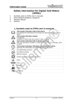
NEVO N O+ 60 00 se eries User U Manu ual The e NEVO+ serries user ma anual has been prepared d by the Vox Power desig gn team to assist a qualifie ed engineers s in corrrectly implementing the e product and d to achieve e the best reliability and performance e. At time of print, the e information co ontained in this document is be elieved to be correct and accura ate. However, specifications s arre subject to cha ange with hout prior notice e and Vox power will not be liab ble for any dam mage caused as a result of the information with hin this document. For continue ed prod duct improveme ent, please repo ort any errors co ontained in the document to Vo ox Power Ltd. NE EVO+ series overview The e NEVO+600 s switch mode power p supply series offers truly t unrivalled power dens sity, providing 600 W at 25 W/in3 in a 5” x 3”x 1U package. It is the ultim mate power so olution for systtem designers s as they addrress the press sing demands for more pow wer with hin less space e. Providing multiple m isolate ed outputs, the e series carry full UL60601 (NEVO+600M M only) and UL60950 (NE EVO+600S only) safety app provals. The e basic system m consists of an a input modu ule together with w up to fourr fully isolated output modu ules. Single ou utput modules s hav ve advanced remote voltage e and current programming g functionality y as standard. While dual ou utput modules s allow for up to eigh ht fully isolate ed outputs. The e input module e delivers up to t 600 W of output o power and a has 4 slotts, each capab ble of separately delivering up to 150 W.. A 5 V, V 200 mA med dically isolated d bias supply together with h an AC_OK signal and a glo obal inhibit sig gnal that can disable all outputs simultan neously, comes as standard on all models s. Outtput modules are available in a range of output voltag ges to suit all applications. a Sing gle output mo odules with vo oltage ranges from 1.5V to 60V, currents s up to 25A an nd paralleling and series capability can resu ult in a voltag ge range up to o 240V and a maximum currrent of up to 100 Amps fro om a single Ne evo+600 conffiguration. Dua al output mod dules have a voltage v ranges s from 1.5V to o 15V and currents up to 5A A with series capability. c By selecting the correct output modules, a custom powerr solution can be configured d in a few min nutes. This ins stantly availab ble custom solution offers o industry y leading pow wer density, to otal system effficiencies of up u to 89% and d suits all type es of applicatio ons a military and tele ecoms. including industrial, medical, aerospace, 2 Contents NEVO+ series overview ...................................................................................... 1 Part numbers and ordering information ................................................................ 4 Installation Notes .............................................................................................. 5 Theory of operation ........................................................................................... 6 Input module operation ...................................................................................... 7 Signalling ........................................................................................................10 Single Output module operation .........................................................................12 Advanced Single Output module features ............................................................15 Series Connected outputs ..................................................................................18 Paralleled outputs .............................................................................................19 Dual Output module operation ...........................................................................23 Audible noise ...................................................................................................26 Mechanical dimensions and mounting..................................................................27 Connectors ......................................................................................................28 Configuring your power supply ...........................................................................29 Safety .............................................................................................................31 EMC compliance ...............................................................................................32 Reliability ........................................................................................................33 3 4 Part numbers and ordering information INPUT MODULES Model NEVO+600S NEVO+600M Details 600 Watt input stage with standard leakage current. 600 Watt input stage with medical leakage current and isolation requirements. OUTPUT MODULES Model 0 1 2 3 4 5 6 7 Nominal voltage Rated current Rated Power 5V 12V 24V 48V 12V Dual 3.3V Dual 12V/3.3V Dual 25A 15A 7.5A 3.75A 5A 5A 5A 125W 150W 150W 150W 75W x 2 25W x 2 75W/25W Adjustment range Unused slots 1.5V‐7.5V 3V‐15V 9V‐30V 18V‐58V 5V‐15V Each Ch 1.8V‐5V Each Ch 5V‐15V/1.8V‐5V Load regulation Line regulation OVP ±50mV ±100mV ±150mV ±300mV ±50mV ±50mV ±50mV ±0.1%Vnom ±0.1%Vnom ±0.1%Vnom ±0.1%Vnom ±0.1%Vnom ±0.1%Vnom ±0.1%Vnom 9V 18V 36V 66V 20V 8V 20V/8V PART NUMBERING SYSTEM NEVO Input Module Product Type S ‐ Standard M ‐ Medical NEVO+600 Slot A – Output # Slot D – Output # Slot B – Output # Slot C – Output # When initially ordering non‐nominal voltage settings add “ /Voltage” after each output # where a special voltage setting is required E.g. If 3.30Vdc is required in slot B and all other slots require nominal voltages then use: NEVO+600M – 1 – 1/3.30 – 2 ‐ 3 The factory will then issue a 3 digit code for your specific configuration that can be used for all future orders of the same configuration When ordering an input unit with no outputs inserted, simply order NEVO+600M or NEVO+600S M ‐ 1 1 2 3 ‐ 0 0 0 Factory Use Use ‘0’ for unused slots. Blanking plates will be inserted at factory 5 Installation Notes This power supply is intended for use within equipment or enclosures which restricts access to authorised personnel only. The instructions in this manual and all warning labels on the product must be followed carefully. Safety All power supplies must be installed correctly in a controlled environment which restricts access to any unauthorised personnel. Equipment and system manufacturers must protect service personnel against unintentional contact with the output terminals. Hazards If series and/or parallel combinations of outputs exceed safe voltage and/or energy levels, the final equipment manufacturer must provide appropriate protection for both users and service personnel. Health and safety To comply with section 6 of the health and safety at work act, a label that is clearly visible to service personnel must be placed on the final equipment, which warns that surfaces of the power supply may be hot and should not be touched when the product is operating. Fusing The power supply has internal single pole fusing in the L (Live) line. Servicing The power supply contains no user serviceable parts. Repairs must be carried out by authorised personnel only. Contact Vox Power Ltd for further information. Cooling For proper cooling of the power supply, the air intake and outlet must not be impeded. Allow 50 mm clearance at both ends and position cabling appropriately. Avoid excessive back pressure in the general system or when using ducting to navigate hot air out of the system. Earth terminal marking To comply with the requirements of UL60950-1, EN60950-1, IEC60950-1, CSA22.2 no. 60950-1, UL60601-1, EN60601-1, EN61010-1, IEC60601-1, IEC61010-1, CSA22.2 no 601-1 where the incoming wiring earth is intended for connection as the main protective earthing conductor and where the terminals for such a connection is not supplied on a component or subassembly such as a terminal block, the user shall add an appropriate label displaying a protective earth symbol in accordance with 60417-2-IEC-5019 directly adjacent to the terminal. The label should be durable and legible and should withstand the 15s rub test as per UL60950-1 section 1.7.15. Mounting The unit can be mounted using the bottom or side mounting points. Each mounting point accepts an M4 screw where the maximum penetration, inclusive of 1.75 mm chassis thickness, should never exceed 4.00 mm. The maximum torque for the M4 screws is 1.50 Nm. Other To prolong the life of the unit, use in a dust free environment. If units are damaged during transit, contact your sales agent or Vox Power and DO NOT apply power to the unit. Always use adequately sized cables and ensure good crimp connections. Use cable supports to minimise stress on connectors. Avoid excessive shock or vibration. General installation parameters Equipment class I Installation category II Pollution degree 2 Material group IIIb (Indoor use only) Flammability rating 94V-2 IP rating IP10 RoHS compliance 2002/95/EC 6 Th heory of operatio on The e diagram belo ow outlines th he topology an nd major interrnal componen nts of a fully assembled a sys stem. Four ou utput slots are e provided and can n be populated d by any combination of ou utput modules s. The remaining componen nts in the block diagram are e used in the inp put module. hou The e input module e is responsible for receivin ng the AC mains line voltage and convertting it to an appropriate DC C voltage whils st providing protecttion from AC line disturbanc ces and preve enting excessive EMI emissions and curre ent harmonics s. The integrated EMII filter attenua ates high frequency currentt emissions to o levels below EN55022 clas ss B. It also provides p single e pole fusing in the live conducto or and protecttion from line disturbances as outlined in EN61000. ush current is controlled by y a resistive ellement upon initial i connecttion to the AC line. Once the internal cap pacitances hav ve Inru bee en charged, th he resistive ele ement is bypa assed to reduc ce losses. Active Power Fac ctor Correction n (PFC) is used to ensure an accurate inp put current wa aveform with extremely low w harmonic con ntent, exceeding the require ements of EN6 61000. This sttage also prov vides active in nput current limiting which prevents ove erloading of th he input stage while mainta aining high pow wer factor. The e output of the e PFC stage ch harges the ho old-up electrolytic capacitorrs which store enough energ gy to allow the system to con ntinue operatin ng during min nor line disturb bances. These e are the only electrolytic ca apacitors in th he entire powe er supply and to furtther increase system reliability, long life and high temperature capa acitors are use ed. A highly efficientt zero voltage switching circ cuit is used to o drive the me edically isolate ed transformer from the hold-up capacito ors. The e output modu ules connect to the transforrmer secondarry and provide e safe isolated d power to a high h performa ance synchron nous recttifier power co onverter which is controlled d using the lattest analog co ontrol technolo ogy to produce superior outtput performa ance in an a extremely rreduced size. 7 In nput mod dule operation Sta artup & shut down The e NEVO+ input modules ope erate from a universal u input voltage rang ge and start automatically a upon application of adequa ate AC mains voltage e (>84Vrms). After a short delay, the glo obal 5V bias supply s starts and a the ACOK K signal goes high to indica ate that the mains vo oltage is present and input stage is operrating correctly. Once the ACOK A signal is high, the outtput modules turn on and a deliver po ower to the ap pplication load ds. The powerr good signals will indicate that t the outpu ut voltages arre within spe ecification. The e diagram below shows the e normal start up/shut down n sequence an nd gives typic cal timings. Typ pical timing va alues: t1 300 ms, t2 50 ms, t3 25 ms, t4 15 ms, t5 = 5 ms m (minimum m), t6 100 ms m ains voltage is removed, the e internal hold d-up capacitorrs will supply power to the load for typica ally 20 ms (t4+t5) When the AC ma m pow wer. The ACOK K signal will go low at least 5ms before tthe output voltages fall belo ow the power good thresho old at maximum leve el. This allows s the application to prepare e for the impen nding loss of power. p The 5V V bias supply will remain on n for typically 100 0ms, after the e output modu ules have turned off. Holld-up For short line dis stubances (<2 20ms), the outtput voltages will not be afffected*. Howe ever, the ACO OK signal may still go low to o warrn that there iis an impendin ng loss of output power. Th he ACOK signa al will return to t the high sta ate once the unit u has reco overed from the t disturbanc ce. *Ou utputs that arre adjusted ab bove the hold--up voltage as s detailed in th heir respective e datasheets, may experien nce a dip in volttage but neve er below the hold-up voltage specified. Idle e power The e idle power of the NEVO+ PSU is extrem mely low when n compared to o similar powe er supplies. With the output m modules enab bled the unit typically only requires r 28 W with no outp put load. To re educe the idle power further the outputs can b be disabled us sing the globa al inhibit (GINH) pin. With the t outputs disabled the un nit typically req quires less tha an 21 W. Ove er temperatu ure Protectio on (OTP) The e input module e is protected from excessiv ve temperatures by means s of various intternal sensors s. If temperature threshold ds are exceeded the e entire unit may m latch off, with no ACOK K warning. To re-enable the e unit the AC mains must be disconnecte ed for approximately y 2 minutes. 8 Power derating NEVO+600 units must always be operated within its stated operating limits. Equipment manufacturers and other users must take appropriate deratings into account at all times when specifying a unit for the intended application. If in doubt contact your sales representative or Vox Power for assistance. There are two main deratings for NEVO+ power supplies, temperature and input line voltage. Temperature deratings apply to both input and output modules, while line deratings apply only to the input module. For temperature, the derating for both input and output modules is 2.5% (of maximum rated power) per degree Celsius above 50°C. While, for input line voltage, the derating for the input module only is 0.7143% (of maximum rated power) per volt below 120Vrms. These deratings can be calculated using the following conditional equations; Line Derating Equation for line derating: 650 600 Pout = Prated*Line derating factor = Prated*(1-(0.007143*(120-Vin)) Otherwise, Pout = Prated 550 Output Power (Watts) If Vin < 120, 500 450 Derate at 4.28W per volt below 120V 400 350 300 250 80 100 120 140 160 180 200 220 240 260 Input Voltage (Vrms) Temperature derating Equation for temp derating: If temp > 50C, Pout = Prated*Temp derating factor = Prated*(1-(Temp-50)*0.025) Otherwise, Pout = Prated Normalised Derating factor 1.1 1 0.9 0.8 Derate at 2.5% per volt above 50˚C 0.7 0.6 0.5 0.4 ‐30 ‐10 10 30 50 70 Temperature Depending on the application conditions, one or both of the deratings may apply. Where both apply, the derating factors given above can be multiplied together to obtain the total derating factor. Example: What are the NEVO+600 input and output module deratings at 60°C at 100V line? Input power rating = Output power rating = Line derating factor = Temperature derating factor = Input power rating = Output 2 power rating = Prated*line derating factor*Temp derating factor Prated*Temp derating factor (1-(0.007143*(120-Vin)) = (1-(0.007143*(120-100)) = (1-(Temp-50)*0.025) = (1-(60-50)*0.025) = 600*0.85714*0.75 = 385.7W 150*0.75 = 112.5W 0.85714 0.75 9 Efficiency The efficiency of the overall unit is dependent on several parameters such as input voltage, load level and on the combination of output modules. The plots below show typical efficiencies of a NEVO+600 over the full load and line voltage range and fitted with four of each type of output module, equally loaded. Typical Line Efficiency (Maximum power) 0.90 575 0.88 Typical Line Efficiency (Derated Power) 0.90 600 600 575 0.88 550 550 0.86 525 0.84 500 475 0.82 450 0.80 OP1 OP4 0.78 80 100 120 140 160 OP2 Pout 180 200 Efficiency Efficiency 0.86 240 475 0.82 450 OP1 OP4 0.78 400 220 500 0.80 425 OP3 525 0.84 80 260 100 120 Efficiency Efficiency Typical Load Efficiency (120Vrms) OP1 OP3 0 50 100 150 200 250 300 350 OP2 OP4 400 160 180 200 220 425 OP3 400 240 260 Input voltage (Vrms) Input Voltage (Vrms) 0.90 0.88 0.86 0.84 0.82 0.80 0.78 0.76 0.74 0.72 0.70 0.68 0.66 140 OP2 Pout 450 500 550 Typical Load Efficiency (220Vrms) 0.90 0.88 0.86 0.84 0.82 0.80 0.78 0.76 0.74 0.72 0.70 0.68 0.66 600 OP1 OP3 0 Output Power (Watts) 50 100 150 200 250 300 OP2 OP4 350 400 450 500 550 600 Output Power (Watts) An estimate of the efficiency for any particular system may be obtained from these graphs using the procedure outlined in the example below. Example: Estimate the efficiency of an NEVO+600-1123, at 160Vrms input and 100W load on each output? 1. Define load efficiencies for each output module at the specified load and 220V. 2. Define change in efficiency from 220Vrms to 160Vrms for each output module. 3. Sum the values from step one and two for each output module. 4. Calculate the average efficiency for the total system. Step Details 1 2 3 4 Є220 (Load chart) ∆Є(220-160) (Line chart) Єx = Є220 + ∆Є(220-160) ЄAVE = (Є1 + Є2 + Є3 + Є4)/4 Slot A OP1 0.84 -0.01 0.83 Slot B OP1 0.84 -0.01 0.83 Slot C OP2 0.87 -0.01 0.86 0.845 Slot D OP3 0.87 -0.01 0.86 1 10 Sig gnalling To reduce cabling g in the end system, s all ma ajor input and output signals and the global 5V bias su upply are wire ed to a single sign nals circuit tha at is accessed d through the connector (J2 2) located at the output side e of the chass sis as shown in n the diagram m belo ow. Pin 1 2 3 4 5 6 7 8 9 10 11 Name N P PG1 I INH1 P PG2 I INH2 P PG3 I INH3 P PG4 I INH4 G GINH A ACOK + +5V Description Po ower Good In nhibit Po ower Good In nhibit Po ower Good In nhibit Po ower Good In nhibit Global inhibit AC C mains signa al Global 5V Bias 12 C COM Co ommon Slot A Slot B Slot C Slot D All of o the signals are reference ed to the bias supply comm mon rail (COM)) and external control and/or monitoring circuits can be b eas sily powered a and interfaced to the PSU th hrough this co onnector. The entire signals s circuit is fully y medically isolated and can be considered c a SELV S output. The table belo ow lists the is solation voltag ges. Signals s to Input Signals s to Chassis Signals s to Output Signals isolation vo oltages 4000 250 250 Vac V V Vdc V Vdc 5V bias supply (Power) A 5V bias supply that can deliv ver up to 200mA is provide ed as standard d on all units. This supply is s available wh henever the AC C mains voltage is connected an nd the input module m is operrating correctly y. To ensure safety, s the folllowing abnorm mal conditions s may y cause the entire unit to la atch off, which h will disable the 5V bias su upply: Over tem mperature of any part of th he unit Over vo oltage on the output o Internall over current (device failurre) AC mains signa al (ACOK [Ou utput]) An ACOK signal is provided to indicate to th he user that th he AC mains v voltage is applied and the in nput module iis operating correctly. The ou utput signal is driven from an a internal operational amp plifier as show wn in the follow wing diagram.. Under norma al ope erating conditiions this signa al gives a warning of 5ms before b the output voltage fa alls below the power good threshold. t How wever, to ensu ure safety, the e following ab bnormal conditions may cau use the entire unit to latch off without an n ACOK warnin ng: Over tem mperature of any part of th he unit Over vo oltage on the output o Internall over current (device failurre) 1 11 Pow wer Good sig gnals (PG1-P PG4 [Output]) Eac ch output mod dule provides a power good (PG) signal to e output volta indiicate when the age is above approximately a y 90% of the t preset volttage for that module. m Each PG signal on an output module is s internally connected throu ugh an opto-is solator to the t signals circuit, which bu uffers the sign nal through a PNP tran nsistor with a 10k pull down n resistor, as shown. The e LED on the ffront of each module m gives a visual con nfirmation of the PG status. Notte that remote e adjustments s of the outputt voltage using the Vco ontrol and Icon ntrol pins do not n change the PG signal thre eshold. The PG G threshold is s always appro oximately 90% % of the voltage set w with the manual potentiome eter. Outtput Inhibits s (INH1-INH4, GINH [Input]) The e signals circuit provides fou ur inhibit inpu uts to disable each e output m module individ dually and a fifth global inhiibit input (GIN NH) to inhibit all mod dules simultan neously. Each inhibit input is internally co onnected through an opto-isolator to the e respective output modules. The basic inte ernal electrica al circuit and timing t diagram ms are shown below. Typica ally, tOFF = 100 μs and tON = 8 ms. To inhibit each output module individually, GINH should be connected to COM, and 5V applied to o the appropria ate input INH H1/2/3/4. To s start with all outputs o inhibitted and then enable e them individually, GINH G should be connected to t +5V, then pull p dow wn the approp priate input IN NH1/2/3/4. If GINH G is left unconnected, then t INH1/2/3 3/4 will all beh have as global inhibit inputs. i.e. 5V on any IN NH input will disable all outp puts. 1 12 Single Outtput mod dule ope eration Pow wer profile The e power profile e diagram below is a voltag ge/current plot that togethe er with the ass sociated table e provides dettails of the ma ain feattures of the cu urrently availa able output modules. m Param meter VNOM (V) VMIN (V) VMAX (V) VOVP (V) IRATED (A) IOCP (A) ( VHICCUPP (V) IHICCUPP (A) PRATED (W) PPEAK (W) OP1 1 5 1.5 7.5 9.5 25 27.5 5 1 22 125 187.5 5 OP2 12 4.5 15 17 15 16.5 2 13.2 150 225 OP3 24 9 30 32 7.5 8.25 4 6.6 150 225 OP P4 4 48 1 18 5 58 6 62 3.75 4.1 125 4 3.3 15 50 217.5 Outtput voltage adjustmentt Eac ch output can be adjusted within w the rang ge as describe ed in the table e above or in the datasheett. Voltage adjustment can be b ach hieved by two methods; 1. Manuall potentiome eter adjustment Usin ng the manua al adjust poten ntiometer, the e preset outpu ut voltage (VSEET) of each output module is adjustable over o the entire e range of VMIN to VMAX as specifiied in the pow wer profile table above. A cllockwise rotattion of the pottentiometer re esults in an e of the output voltage. incrrease of the output voltage while an antii-clockwise rottation results in a decrease 2. Remote e voltage pro ogramming Usin ng remote voltage program mming, the output voltage may m be adjustted beyond th he VMIN and VMAX range specified in the po ower profile table abov ve. However,, certain preca autions must be b taken to en nsure correct operation. Ple ease see the “Advanced “ outtput mod dule features”” section for more m details. Ove er Voltage Protection (O OVP) In the t event of a an output mod dule fault, the modules are protected aga ainst excessive output volta ages. This is im mplemented as a a fixe ed voltage thre eshold (VOVP, in the table ab bove) and if the output volttage exceeds this threshold d the entire ch hassis will be latc ched off. To re esume operatiion of the unitt, disconnect the t AC input voltage v for 2 minutes, m remo ove the faulty y output modu ule and d reconnect th he AC input vo oltage. Notte that no warrning is given on the AC_OK K signal for fa aults of this type. Ove er Current & Short Circuit Protection n (OCP & SCP P) For increased saffety and reliab bility all outpu ut modules in the NEVO serries have overr current and short s circuit protection. p The e er current thre eshold is typic cally set at 110 0% of the rated current and has a constant current, straight s line ch haracteristic that ove reduces the outp put voltage as the load resis stance decreases. If the output voltages falls below th he hiccup volta age threshold (VHICCUP) the mod dule enters sh hort circuit pro otection mode e. In this mode the output module uses a hiccup scheme to reduce system losses an nd potential da amage. When in this mode,, the output will w be enabled d for approxim mately 3% of the t time, disa abled for 97% % and will attempt to restartt at approximately 125 ms intervals. The e module remains in this sttate until the sho ort circuit cond dition is remov ved, at which point the module returns to t normal ope eration. 1 13 Rev verse Curren nt Protection n (RCP) The e standard outtput modules use synchronous rectification in the outp put stages to achieve high efficiency and d as a result th he outputs can both h source and sink s current. The T sink curre ent is internally limited to approximately -6% of the maximum m rated d current. However, in applicatio ons where the e output modu ules are conne ected to exterrnal power sou urces such as batteries or plies certain precautions p must be observ ved to preventt damage to th he unit. other power supp ould never be directly conne ected to to external power sources witho out some form m of reverse cu urrent protecttion The outputs sho c mos sfet. If protecttion is not use ed, large reverse currents which w will ultim mately result in such as an external diode or controlled mage to the unit will occur, especially wh hen the AC ma ains is disconn nected. dam Outtput module Average and Peak powe er All modules have e an average and a peak pow wer rating. The e average pow wer of each un nit must at all times remain n below it’s spe ecified limit. However, each output can deliver up to 150% of it’s av verage power rating for a maximum m of 5 seconds at 50% duty cycle, subje ect to the currrent limit not b being exceede ed and subject to the overa all average power drawn be eing less than the spe ecified average e power rating g (including any input deratting due to temperature or line voltage).. The available e peak power is a function of the output voltage and maximum m current for each module.. Full peak pow wer is only po ossible when the t output ed to VMAX and d the maximum current is drawn d from th he module. No ote that both average a and peak p power volttage is adjuste ratings are subje ect to the sam me temperature derating as the input module (derate by b 2.5% per °C ° above 50°C C), but are no ot sub bject to any lin ne derating. Sta art up & Shutt down All outputs o are designed to have a regulated monotonic start-up s with a rise e time of approximately 3 ms m as shown in the diagram m right. The po ower goo od signal stays s low until the e voltage exce eeds the powe er good thresh hold (≈9 90%). Where multiple o output module es are used, th he default start up scheme is ratio-metric with all outputs sttarting at the same time as s shown in the e diag gram right. Ex xternal contro ol circuits may y be used to im mplement trac cking or seque enced start up p if necessary. e outputs are not designed to start into a pre-biased lo oad and may The disc charge any ex xternally capac citance before e beginning to o ramp the output volttage up in the e normal way. At shutdown s the outputs enterr a high imped dance state. Where W no exte ernal load d is present itt may take som me time for th he voltage to decay. When driv ving inductive loads, care must m be taken to limit the voltage v at the output terminals so as to prev vent damage to t the unit. nchronisation Syn All output o modules in the same chassis are synchronised. The typical operating o freq quency is 260kHz and parallleled/seriesed d unitts will not pro oduce beat frequencies. 1 14 Rip pple and Nois se The e ripple and no oise figures sttated in the da atasheet are defined d based on a standarrd measuring method. To obtain the sam me resu ults the same test setup must be used and care must be taken to e eliminate any parasitic noise pickup. The e diagram belo ow sho ows details of the setup and d also sources s of noise pickup. Ove er Temperatture Protectio on (OTP) Eac ch output mod dule is protectted against ex xcessive tempe eratures. In th he event of th he internal tem mperatures ex xceeding safe leve els the entire unit may be latched off. To o resume operration of the unit, u disconnect the AC inpu ut voltage for 2 minutes, ens sure external a ambient temp peratures are within w specific cations and th hen reconnect the AC input voltage. Note e that no warn ning is given g on the AC_OK A signal for f faults of th his type. Tra ansient respo onse The e NEVO outputt modules hav ve been espec cially designed d to have high h reliability an nd to achieve this t all electro olytic capacito ors hav ve been elimin nated from the e design. Due to this, high dynamic load transients ca an cause relatiively high volttage deviation ns at the output and although the outputs have a very high loo op bandwidth with typical recovery r times s of less than 100μs, the ns may still be e excessive for some applications. volttage deviation An example application is deta ailed in the dia agram below and shows typ pical response es at the term minals of the output module and d at the load. Notice that th he voltage dev viation due to cable inducta ance exceeds the t module re esponse and h hence a capacitor loca ated at the mo odule termina als will have litttle effect at the t load. The optimum o solu ution is to loca ate a low impe edance elec ctrolytic capac citor at the loa ad which will eliminate e the inductive cab ble drop and also reduce the e typical volta age deviation at a the module. 1 15 Ad dvanced Single Output O m module fe eatures mote voltage e programming (Externa al voltage control) Rem The e output voltag ge of the mod dule can be ad djusted using an external voltage source connected be etween the CO OM and Vcontrol pins s on the signa als connector J5 J as shown below. b In this t configurattion the outpu ut voltage will follow the typ pical equation n below, Vo = Vset((1.8-V Vctrl) / 0.6), where w Vset is the manual preset voltage of the module e. The e output voltag ge can be con ntrolled from 0% 0 to 300% of o the preset voltage v using this control method. m Howe ever, care mus st be taken t to ensu ure the output voltage does not exceeed the OVP levell, as this is considered a safety hazzard and a will latch the entire unit off. To o determine the level of con ntrol voltage that t will trigge er OVP, insertt Vovp into the equation ab bove. Exa ample: V, Vset = 5V; Vovp = 9.5V => Vctrl = 1.8-(Vovp*0.6 1 6/Vset) = 0.66 6V Hen nce, Vctrl shou uld never fall below 0.66V, otherwise OV VP may latch the t entire unitt off. Alte ernatively, by manually adjusting the outtput voltage to t less than 1//3rd of the OVP voltage ensures that OVP P can never be e trip pped by remotte voltage con ntrol. Also o, remote adjustment of the output volta age using the Vcontrol pin does d not affec ct the preset power p good th hreshold. Hence, rem motely adjustin ng the output voltage below w 0.9*Vset wiill cause the power p good sig gnal to go low w. Where tight volta age adjustmen nt tolerances are required, it is recomme ended to use external e circuitry to provide e closed loop con ntrol of the Vco ontrol pin. 1 16 Rem mote currentt programmiing (Externa al voltage con ntrol) The e output curre ent limit of the e module can be reduced us sing an extern nal voltage source connecte ed between th he COM and Icon ntrol pins on tthe signals connector as sh hown below. In n practice this s also means that t the outpu ut can be used d as a modula ated or constant c curre ent source. In the t diagram a above, Vi_out is an internal voltage sourc ce that is prop portional to th he internal inductor current and app proximates the e equation, Vi_o 25)), where Irrated is the maximum rated d current for the t module. out = 0.6 + (Iout o /(Irated*1.2 In this t configurattion the outpu ut current limit will approxim mate the follo owing equation n, Ilimit = (Vctrl-0.6 6)*Irated*1.25, where Irated is the maxim mum rated current for the module. m It is s not possible to increase th he maximum current limit of o the module e, and control voltages (Vctrrl) exceeding 1.53 V will have no effect e on the c current limit. When using an o output module e as a modulatted current so ource, the output voltage sh hould be manually adjusted d to the max ximum that w will be required d by the application and thiis will be the upper u voltage e limit. Once th he load is con nnected, the output current ca an then be mo odulated by applying a conttrol voltage as s described ab bove. Notte that the pow wer-good thre eshold level is s fixed and deffined by the manually m preset voltage. He ence, while the output mod dule is limiting or mod dulating the output o current the PG signal may go low. Where tight curre ent adjustmen nt tolerances are required, it is recomme ended to use external e circuitry to provide e closed loop con ntrol of the Ico ontrol pin. Outtput current measureme ent The e output curre ent of the mod dule can be measured using g the Icontrol signal. If this pin p is unloaded its output voltage will follow the equation, 25)), where Irated is the ma aximum rated current for th he module. Vi_o out = 0.6 + (Iout o /(Irated*1.2 r Notte that the Icontrol output vo oltage is repre esentative of the t internal in nductor curren nt not the actu ual load current. However, this s will only hav ve an influence e during dynamic events. Itt is recommen nded to add an external am mplifier (as sho own above lefft) 1 17 en using the Icontrol signal to t measure th he output currrent as loading g the Icontrol signal, s even with w microamps can cause th he whe current limit to b be reduced. If it is required to measure the output current and adjust the output current limit simultaneously, s can be achie eved by using a clamp circuit instead of a voltage sourrce to adjust the t current lim mit, while conttinuing to use an this amplifier to meas sure the output current. An n example circ cuit is shown above a right. In this case Vctrl c will control the current limit ed Icontrol sign nal will provide a measurem ment of the ou utput current. while the amplifie Rem mote sensing g Rem mote sensing is available on n all output modules m and ca an be used to compensate for any voltag ge drop in the main power lead ds between th he power supp ply and the loa ad. To implem ment remote sensing s connect the positive e sense pin (S S+, connector J5.2 2) to the posittive side of the remote load d and the negative sense pin (S-, connec ctor J5.1) to the negative side of the rem mote load d. The voltage e will be regulated at the po oints where th he sense cable es are connec cted. n against worn n out power ca ables or accidental power cable c removal is provided and prevents damage d to the e Active protection e. An internal circuit measures the voltag ge between S+ + to V+ and SS to V-, when n this voltage exceeds the unitt in each case thre esholds speciffied in the dattasheet, the output voltage is reduced to o benign levels s. During systtem design, ca are must be take en to ensure p power cables have a sufficiently low volttage drop at maximum m load d current to en nsure this pro otection does not n actiivate unintenttionally. In systems s where remote sens sing is not use ed, the outputt voltage at th he power term minals will be slightly s higherr than that at the sen nse terminals. This voltage difference is termed, t open sense offset and a occurs du ue to internal bias b currents in the sensing g circ cuit. Factory set units are se et with the se ense cables co onnected unles ss otherwise specified. s Loc cal Bias supp ply A lo ocal non-isolatted +5 V bias supply is provided on each h output modu ule (+5 V on J5.6, J referenc ced to COM on n J5.5). This sup pply is intende ed to power interface circuitts for monitorring and contrrolling the output modules, such as amplifying the current output signal as described earrlier. The outp put can supply y up to 10mA maximum, an nd exceeding this t can dama age the unit. Also o, as COM is c connected to an a internal vo oltage that is NOT N equivalent to S- or V-, particular atttention must be given to grounding issues s when interfacing COM to any a control cirrcuit in the ap pplication. Con nnecting COM to S- or V- may m result in mage to the unit. dam 1 18 Se eries Con nnected outputs NEV VO output mo odules of the same s type can n be seriesed in any numbe er to achieve higher h output voltages, eve en across multtiple cha assis! The follo owing instructtions must be followed for output o module es configured in this manne er. WARNING! Energy and a voltage hazards h may y arise when individual modules are seriesed. s See the Safety section forr more detailss. WARNING! When modules are seriesed, their inhibit lines (J2), if used,, should be paralleled. p Inhibiting se eriesed modu ules individua ally may cau use damage Iso olation to gro ound Carre must be tak ken not to exc ceed the outpu ut module isolation to chas ssis ground wh hen seriesing outputs. Each h output is ratted for 250 volts max ximum between each outpu ut terminal an nd chassis gro ound. Exceedin ng this voltage may damag ge the unit. Rem mote sensing g For seriesed mod dules, remote sensing is achieved by con nnecting the upper u most po ositive sense terminal (S+) and the lower mos st negative se ense terminal (S-) from the e series of modules to their respective loa ad regulation points. All inn ner sense term minals in the s series must be daisy chaine ed, S+ to S- from f the first module in the e series to the e last module in the series. An exa ample of two s seriesed modu ules is shown below. Ser riesed remotte voltage/cu urrent control Rem mote voltage a and/or curren nt control is po ossible with se eries connecte ed output mod dules using th he advanced V-control V and I-co ontrol function ns as describe ed earlier. How wever, individual control of each module can be complex as the varrious control term minals are refferenced to the positive outtput of the pre eceding module and require e the use of multiple m isolate ed control volttages to attain n control overr the full voltage range. In practice, p indiv vidual control of each modu ule is rarely re equired and a more straightforw ward method is to control all a outputs sim multaneously w with a single control c voltage. With NEVO output modu ules this s is achieved w with the use of o the Nevo Se eries Tracker Interface, I the datasheet for this interface is available from the Vox Pow wer website i.e e. www.vox-p power.com. By y using the se eries tracker in nterface all mo odules in a se eries can be co ontrolled by a sing gle control voltage that can n be reference ed to the COM (J5.5) pin on n any module. SEL LV precautio ons Where series com mbinations of output modulles exceed 60 V, the outputt can no longe er be considerred SELV (Saffety Extra Low w nce the final equipment e manufacturer mu ust provide su uitable protecttion for both users u and serv vice personne el. Volttage) and hen 1 19 Pa aralleled outputs s NEV VO single type e output modu ules of the sam me type can be b paralleled in any number within the sa ame chassis to t achieve higher output currents. WARNING! Energy hazarrds may arise when individu ual modules are a paralleled. See the Safetty section for more details. WARNING! When mod dules are para alleled, their inhibit lines (J2), if used, sh hould also be paralleled. Inhibiting paralleled mo odules individu ually may cause damage o each paralleled module should s be adju usted as close e as possible. For best performance, the outtput voltages of dure below to o achieve the most m accurate e results: Follow the proced 1. 2. 3. Connect all the t negative power p cables together. t Adjust the first module (A A) to the desirred voltage. Connect a vo oltmeter betw ween the posittive terminal of o the first mo odule (A) and the positive te erminal of the e second module (B) and ad djust the seco ond module (B B) until the vo oltage is within n +/-0.2%.. maining modules, always using the positiv ve terminal off the first mod dule (A) as the e Repeat step 3 for the rem 4. reference. c operate in n two distinct modes, Norm mal parallel mo ode or Share parallel p mode. When paralleled,, the outputs can rmal parallel mode Nor For normal parallel mode, the positive powe er cables shou uld be connectted together and a the negattive power cab bles should be e con nnected togeth her. No other connections are a required as shown in the diagram below. In this t mode the highest adjus sted output module m will sup pply all of the load current until it’s curre ent limit is rea ached. If the lo oad dem mand exceeds s this level the e output voltag ge will drop to o the level of the next highest adjusted module m and th hat module wiill beg gin to supply tthe load current while the first module co ontinues deliv vering full currrent. This proc cess repeats ffor the total num mber of paralleled modules. The diagram m above shows s the VI curve e for such a sy ystem. 2 20 Outtput modules that are not delivering d currrent will typica ally sink a small amount of current from the other outtputs, but this s will not exceed -6% of each modules m maxim mum rated current. Typ pically, system m reliability is reduced in this mode as the higher adjusted modules will do most of the work with w the lower adjusted modules only deliverring current du uring peak loa ad demand. Sha are parallel mode m In Share paralle el mode, the outputs o are pa aralleled as be efore and the Icontrol I pin fo or each modulle is connected together as own in the diag gram below. sho Con nnecting the Icontrol pins to ogether forces s all the outpu uts to deliver the same currrent, ensuring g that the systtem reliability y is max ximised and the work load is distributed evenly across s all paralleled d modules. In this t mode the lowest adjustted output mo odule will dete ermine the acttual output vo oltage and all higher adjustted outputs wiill reduce their volta age. There ma ay be a small amount of cirrculating curre ent between the t modules, approximately a y 6% of the max ximum rated current for ea ach module. The e current outp put signal (Icontrol) can still be used to measure m the output o currentt but it must be b scaled by N, N where N is the t num mber of paralleled modules. WARNING! Care C must be e taken to avo oid differential voltages between b the negative pow wer output te erminals of th he paralleled p mo odules as thiss can cause errors at the e control pinss. To avoid th his, it is recom mmended that a low im mpedance co onnection be e made betwe een the nega ative power terminals t clo ose to the PS SU output and cables th hen connecte ed from this common point to the load d. Par ralleling acro oss multiple chassis Paralleling across s multiple cha assis is not possible withoutt external prottection (such as external diodes or contrrolled MOSFET Ts) to prevent p circula ating currents s between eac ch chassis. Faiilure to provid de such protec ction may resu ult in damage e to the units. Con nsult Vox Power for details on how best to t implement such applications. Where units are paralleled acrross multiple chassis, c the ou utputs in each h chassis will not be synchrronised and th he peak to pea ak s output ripple may contain beat frequencies in the audio spectrum. 2 21 Par rallel remote e sensing Rem mote sensing can be used as a normal with h paralleled modules. m The sense s lines (S+ and S-) from each of the e output modu ules sho ould be connec cted together,, S+ to S+, an nd S- to S- as s shown below w. This should be done close e to the powe er supply outp put and d a single pair of cables bro ought from the ese sense line es to the load. Keeping cable lengths to a minimum an nd using twiste ed pairrs where nece essary will help reduce noise pickup in th he sense lines. N+1 configurattions onfigurations, a suitably ratted diode (or controlled MO OSFET) must be b used on each output to When using N+1 redundant co c a systtem failure. However, the d diode introduc ces voltage drops between the t supply and prevent a device failure from causing nificantly degrrade the load regulation. To o counteract this, t the remo ote sense lines s can be used to regulate th he the load that sign ad as shown below. b volttage at the loa Typ pically, this configuration ca an damage the e internal sense resistors used within a power p supply. However, the e NEVO outpu uts hav ve integrated protection to prevent this type t of damag ge and are com mpletely N+1 compatible without w any ad dditional exterrnal protection circuittry. Note that only the posittive sense terrminal is prote ected and diod des should be used in the positive p nnection only. con 2 22 Par ralleled remo ote voltage/ /current adju ust The e simplest way y to achieve re emote voltage e/current prog gramming witth paralleled outputs o is to operate o the mo odules in sharre parallel mode. Fo ollow the proc cedure outlined earlier to co onfigure the outputs in sharre parallel mo ode and once configured c in this mod de, all the Vco ontrol and CO OM pins can be e connected to ogether. Remo ote voltage/cu urrent program mming can th hen be perform med exa actly as with a stand-alone module. It is s not recommended to use remote voltag ge/current pro ogramming in n normal paralllel mode. WARNING! Care C must be e taken to avvoid differenttial voltages between the negative po ower output te erminals of the paralleled p mo odules as thiis can cause e errors at the e control pinss. To avoid this, it is reco ommended th hat a low impedance cconnection be e made betw ween the neg gative power terminals clo ose to the PS SU output an nd cables then t connectted from this common po oint to the loa ad. 2 23 Du ual Output modu ule opera ation Pow wer profile The e power profile e diagram below is a voltag ge/current plot that togethe er with the ass sociated table e provides dettails of the ma ain feattures of the cu urrently availa able dual outp put modules. Parameter C Channel VNOM (V) VMIN (V) VMAX (V) VOVP (V) IRATED (A) R IOCP (A) PRATED (W) R Top 12 5 15 20 5 5.25 75 OP5 Botto om 12 2 5 15 5 20 0 5 5.2 25 75 5 Top 3.3 1.8 5 8 5 5.25 25 OP6 O Bottom 3.3 1.8 5 8 5 5.25 25 Top 3.3 1.8 5 8 5 5.25 25 OP7 Botttom 1 12 5 1 15 2 20 5 5.25 7 75 Outtput voltage adjustmentt Eac ch output can be adjusted within w the rang ge as describe ed in the table e above or in the datasheett. Voltage adjustment can be b ach hieved using th he manual adjjust potentiom meter, the pre eset output vo oltage (VSET) of o each outputt module is ad djustable over the entire range of VMIN to VMAX as specified in the power proffile table abov ve. A clockwise rotation of the t potentiom meter results in n an incrrease of the output voltage while an antii-clockwise rottation results in a decrease e of the output voltage. Rem mote voltage p programming is not availab ble on dual output modules. Ove er Voltage Protection (O OVP) In the t event of a an output mod dule fault, the modules are protected aga ainst excessive output volta ages. This is im mplemented as a a fixe ed voltage thre eshold (VOVP, in the table ab bove) and if the output volttage exceeds this threshold d the entire ch hassis will be latc ched off. To re esume operatiion of the unitt, disconnect the t AC input voltage v for 2 minutes, m remo ove the faulty y output modu ule and d reconnect th he AC input vo oltage. Notte that no warrning is given on the AC_OK K signal for fa aults of this type. Ove er Current Protection (O OCP) For increased saffety and reliab bility all dual output o module es in the NEVO O series have over current protection. The over current thre eshold is typic cally set at 10 05% of the ratted current an nd has a hiccu up mode chara acteristic that turns off the output if the load current exceeds the threshold. The output will w remain offf for a certain period and th hen attempt to o restart. The e module rema ains in this state untill the over load d condition is removed, at which w point th he module returns to norma al operation. Notte that hiccup mode currentt limit scheme es can cause startup s issues s in certain circumstances where w load currrents plus an ny cap pacitive charging currents exceed the currrent limit. For reliable designs the user should s ensure e the worst ca ase measured starrtup current does d not excee ed 90% of the e rated curren nt. 2 24 Rev verse Curren nt Protection n (RCP) Nev vo Dual output modules use e synchronous s rectification in the output stages to ach hieve high effiiciency and as s a result the outputs can both h source and sink s current. The T sink curre ent is internally limited to approximately -6% of the maximum m rated d current. Dua al output mod dules should never be directtly connected to to external power sourc ces without so ome form of re everse currentt protection such a as an externall diode or controlled mosfett. If protection n is not used, large reverse e currents whiich will ultimately resu ult in damage e to the unit will w occur, espe ecially when the AC mains is disconnecte ed. Sta art up & Shutt down All outputs o are designed to have a regulated monotonic start-up s with a controlled rise time which h is specified in the datashe eet. The e power good signal stays lo ow until the voltage v for botth outputs is with w the powe er good thresh hold range (≈6 68% to 120% %). Dua al outputs are not designed d to start into a pre-biased load and may y discharge an ny externally capacitance c be efore beginnin ng to ramp r the outp put voltage up p in the norma al way. At shutdown s the outputs enterr a high imped dance state. Where W no exte ernal load is present p it may y take some time for the volttage to decay. When driving inductive loads, care mus st be taken to o limit the volttage at the ou utput terminals so as to prevent damage to the unit. Syn nchronisation All dual d output m modules in the e same chassis s are synchron nised. The typ pical operating g frequency is s 260kHz and seriesed units s will not produce beat frequenc cies. Rip pple and Nois se The e ripple and no oise figures sttated in the da atasheet are defined d based on a standarrd measuring method. To obtain the sam me resu ults the same test setup must be used and care must be taken to e eliminate any parasitic noise pickup. The e diagram belo ow sho ows details of the setup and d also sources s of noise pickup. Ove er Temperatture Protectio on (OTP) Eac ch output mod dule is protectted against ex xcessive tempe eratures. In th he event of th he internal tem mperatures ex xceeding safe leve els the entire unit may be latched off. To o resume operration of the unit, u disconnect the AC inpu ut voltage for 2 minutes, ens sure external a ambient temp peratures are within w specific cations and th hen reconnect the AC input voltage. Note e that no warn ning is given g on the AC_OK A signal for f faults of th his type. Tra ansient respo onse The e NEVO Dual o output module es have been especially des signed to have e high reliabiliity and to ach hieve this all electrolytic e cap pacitors have b been eliminate ed from the design. As a re esult, the typic cal output cap pacitance of th he module is relatively r low and high h dynamic loa ad transients can c cause rela atively high vo oltage deviatio ons at the outtput. Where th his causes an application issu ue, external lo ow impedance e electrolytic capacitance c may be added to t improve the transient response. How wever, for Dua al output mod dules the maximum recomm mended extern nal capacitanc ce is 220uF. Exceeding E this s value may ca ause starrtup issues. Par rallel operatiion Nev vo Dual Outpu ut modules cannot be paralleled. Paralleling dual outpu ut modules may result in damage. Ser riesed operation Nev vo Dual Outpu ut modules can be seriesed. Tem mperature D Derating For Dual Output modules the temperature t d derating factor applies to ou utput current not output po ower. 25 Remote sensing Remote sensing is available on all Dual output modules and can be used to compensate for a small voltage drop in the main power leads between the power supply and the load. To implement remote sensing connect the positive sense pin [S+, connector J5.1 (Top) or J5.3 (Bottom)] to the positive side of the remote load and the negative sense pin [S-, connector J5.2 (Top) or J5.5 (Bottom)] to the negative side of the remote load. The voltage will be regulated at the points where the sense cables are connected. In systems where remote sensing is not used, the output voltage at the power terminals will be slightly higher than that at the sense terminals. This voltage difference is termed, open sense offset and occurs due to internal bias currents in the sensing circuit. Factory set units are set with the sense cables connected unless otherwise specified. Isolation Each output channel in a Nevo Dual output module is fully isolated. Each output is rated for 250 volts maximum between each output terminal and chassis ground. Exceeding this voltage may damage the unit. 26 Audible noise The following series of plots characterise the audible noise from the NEVO+1200 power supply over various conditions. These plots can be used to estimate the actual audible noise for any application. Noise vs Load (25°C) 56 120Vac 54 220Vac 52 dBA 50 48 46 44 42 40 0 100 200 300 Pout 400 500 600 Noise vs Input voltage (25°C, 600W out) 60 57.5 52.5 50 47.5 45 120 140 160 180 200 Input Voltage (Vrms) 220 240 260 Noise vs Ambient temperature (600W out) 65 dBA 60 55 50 45 150Vac 170Vac 200Vac 40 ‐20 ‐10 0 10 20 Ambient temperature 30 40 50 Noise vs Ambient temperature (Line derated) 65 60 dBA dBA 55 55 50 45 85Vac 102Vac 120Vac 40 ‐20 ‐10 0 10 20 Ambient temperature 30 40 50 27 Me echanica al dimensions an nd mountting SCREW WS MH1, MH2, MH3, MH4, MH H5 Screw type M4 Tightening Penetration depth Tighten to 1.5 Nm 4.00mm max m including ch hassis OUTPUT MOD DULES x 8 M3x5, C/Sink, Posi, Stainless Steel Screw type Tightening Penetration depth Tighten to 0.75 Nm Defined by y screw CHASSIS x 5 Screw type Tightening Penetration depth M3x5, C/Sink, Posi, Stainless Steel Tighten to 0.75 Nm Defined by y screw FAN x 2 Screw type Tightening Penetration depth M3x24, C/S Sink, Posi, Stain nless Steel Tighten to 0.75 Nm Defined by y screw 2 28 Co onnectorrs PINOUTS J1 C Circuit 1 2 3 Details Live Earth Neutra al J2 C Circuit Details 1 Power Good 2 Inhibit 3 Power Good 4 Inhibit 5 Power Good 6 Inhibit 7 Power Good 8 Inhibit 9 10 11 12 C Circuit 1 C Circuit 1 C Circuit 1 2 3 4 5 6 Slot A Slot B Slot C Slot D Global Inhibit AC OK +5V 20 00mA Bias Supp ply COM J3 Details Positive Output J4 Details Negativ ve Output J5 Details - Sense e + Sens se Voltage e Control Curren nt Control / Sharre / Out COM +5V lo ocal bias supply MATING PART DET TAILS M MANUFACTUR RER RE EF. DETAILS HOUSIN NG TERMINAL J1 MAINS INPUT: 3 Pin, 5.08mm, witth Friction Lock, 18--24 AWG M MOLEX 10013036 6 8701031 J2 GLOBAL SIGNA ALS: 12 Pin, 2mm, with w Friction Lock, 24-30 2 AWG M MOLEX 51110126 60 503948051 J2 IDT ALTERNAT TIVE FOR J2 M MOLEX 87568127 73 N/A J3/J4(1) OUTPUT POWE ER TERMINAL: TAB SIZE S 6.35mmx0.8m mm V VARIOUS N/A N/A J5 OUTPUT SIGNA ALS: 6 Pin, 1.25mm m, with Friction lock, 28-32 AWG M MOLEX 15102106 600 50058800 No otes 1. Terminal and Wire W current ratting must excee ed maximum sho ort circuit outpu ut current. Eg. Output O 1 = 25A*1.25 = 31.25A Amps 2. Direct equivale ents may be use ed for any connector parts 3. All cables must be rated 105° °C min, equivale ent to UL1015 29 Configuring your power supply The NEVO+600 power supply is designed to be used as part of an end-system in a restricted environment and therefore should only be accessible to qualified and trained personnel. Persons attempting to configure a unit must have the necessary knowledge and training before doing so. Incorrect configuration may cause damage to the power supply and may affect the warranty of the power supply. Output power modules may be added, replaced or moved by strictly following the sequence of operations described below. Please contact Vox Power or your distributor for assistance in configuring your power supply. STEP 1: Remove the power connection and all other connections from the power supply. WARNING! Leave the unit to stand for a minimum of 3 minutes after removing all power and other connections from the unit before attempting to configure or re-configure the power supply. Always remove the power before handling the unit. During operation the external surface of the unit can become hot. Leave to stand for 10 minutes to allow the unit to cool down before handling the unit. Dangerous voltages are present within the power supply. Covers may only be removed by qualified personnel when the power supply has been disconnected from the mains supply voltage for more than 3 minutes. Covers must be replaced and all screws secured properly before reconnecting to the mains voltage. STEP 2: Remove all screws. There are 2 screws at the fan side, 5 screws on the sides and 8 on the top (2 for each slot). The lid can now be removed. Ensure that all the output modules are loose from the lid before removing the lid. Top x 8 Fan x 2 Side x 5 30 STEP3: Once the lid is removed modules can be removed and replaced as required. The 15 pin header on the output module plugs directly into the connector on the printed circuit board. Each connector is keyed to prevent improper insertion. Insert the output module and ensure it is pushed down properly. Do not remove the plastic cover on the front-end of the unit. Plastic Cover STEP 4: Once the modules are replaced and the new configuration is complete and the lid can be closed again. A blanking plate must always be used whenever a slot does not contain an output module. Attach blanking plates to the lid before closing it. Ensure the plastic cover is in place before closing the lid again. When closing the lid ensure that each output module slots properly into its corresponding slot in the lid. Insert all the screws and tighten to 1NM. Do not over tighten. Each Output Module must slot properly into corresponding slot in lid WARNING! Do not apply power to the power supply before replacing the lid and securing all the screws. STEP 5: Reconnect the power cable and apply power to ensure all the output modules are working by checking that the LED light on each output module comes on. Always check the output voltage of each module to ensure it is adjusted to your requirements. Remove power and attach all other cables. The unit is now ready for use. 31 Safety The NEVO unit has been designed to comply with the Low Voltage Directive 73/23/EEC (LVD) and is CE marked to show its compliance. When correctly installed (according to the installation manual) in a limited access environment the NEVO+600S complies with the requirements of UL60950-1, EN60950-1, IEC60950-1, CSA22.2 no. 60950-1 and the NEVO+600M complies with the requirements of UL60601-1, EN60601-1, EN61010-1, IEC60601-1, IEC61010-1, CSA22.2 no 601-1. The power supply should not be operated close to combustible materials or atmosphere. Care should be taken to ensure liquid or metal shavings do not enter the power supply as this can cause a fire hazard. The power supply does not contain any user serviceable parts and should be returned to Vox Power for repair. Approval limitations (NORTH AMERICA) When this product is used with 180VAC–253VAC mains where no neutral is present, connect the two live wires to L (Live) and N (Neutral) on the input connector. WARNING! Seriesed modules with combined voltages exceeding 60 volts are not considered SELV. Paralleled and/or seriesed modules with combined energy ratings greater than 240 VA may cause energy hazards. The equipments manufacturer must provide additional and adequate protection to service and technical personnel. Always remove the power before handling the unit. During operation the external surface of the unit can become hot. Leave to stand for 10 minutes to allow the unit to cool down before handling the unit. Dangerous voltages are present within the power supply. Covers may only be removed by qualified personnel when the power supply has been disconnected from the mains supply voltage for more than 3 minutes. Covers must be replaced and all screws secured properly before reconnecting to the mains voltage. Parameter Isolation voltage Isolation clearance Isolation creepage Leakage current Agency Approvals Standards Agency File Numbers Details Min Max Units Input to Output 4000 Vac Input to Chassis 1500 Vac Output to Chassis 250 Vdc Output to Output 250 Vdc Primary to Secondary (Reinforced) 7 mm Primary to Chassis (Basic) 2.5 mm Primary to Secondary (Reinforced) 12 mm Primary to Chassis (Basic) 4 mm Medical: 265 Vac, 63 Hz, 25°C 300 µA Standard: 265 Vac, 63Hz, 25°C 1500 CURUS, Demko, CB Certificate IEC/EN60950-1; UL60950-1/CSAC22.2No.60950-1-03; IEC/EN60601-1; UL60601-1; CE Mark: LVD 73/23/EEC. UL : E316486 32 EMC compliance To support compliance of the final system design with the EMC directive 89/336/EEC, the NEVO PSU has been designed and tested to the following standards. Parameter Emissions Standard Level Radiated electric field Conducted emissions Harmonic distorsion Flicker and fluctuation EN55011, EN55022, FCC EN55011, EN55022, FCC EN61000-3-2 EN61000-3-3 B B Compliant Compliant EN61000-4-2 (15 kV air, 8 kV contact) EN61000-4-3 (10 V/m) EN61000-4-4 (4 kV) EN61000-4-5 (1 kV L-N, 2 kV L-E) EN61000-4-6 (10 V) EN61000-4-8 (10 A/m) EN61000-4-11 (EN55024) 4 3 4 3 4 3 Compliant Immunity Electrostatic discharge Radiated RFI Fast transient burst Input line surges Conducted RFI Power freq. Magnetic field Voltage dips For radiated and conducted emissions, compliance of the final system relies on proper installation of the PSU component. The installation guidelines detailed below should be followed. Installation guidelines for EMC NEVO units should be mounted within a metal enclosure using the mounting fixtures provided. If the application enclosure is not metal then a metal ground plate should be used to mount both the power supply and the load. Decoupling the loads to the chassis or ground plate with suitably rated 100nF capacitors can assist in reducing emissions. Both input and output cables should be fixed as close as possible to the ground plate or metal enclosure. Also, input and output cables should be separated as much as possible. Output power and sense cables should be twisted pairs and routed parallel to each other. Do not twist sense and power cables together. All cables lengths and loop areas should be minimised. Where cables must enter or exit the enclosure, good high frequency 100nF decoupling capacitors of sufficient voltage rating should be connected to the cables as close to the entry/exit point as possible. For further details or assistance contact Vox Power. 33 Reliability The Nevo series has undergone extensive testing, including HALT and Environmental testing. Reliability data is collected on an ongoing basis. Please contact Vox Power or your distributor for the most up to date reliability data. Vox Power Ltd. reserves the right to change or improve any part of the specification, electrical or mechanical design or manufacturing process without notice. Please consult your local distributor or contact Vox Power to ensure that you have the latest specification before using your product. For other information relating to the use of the product please refer to the latest NEVO user manual. Vox Power reserves the right to make changes without notice to any of its products. Vox Power does not assume any liability arising out of the use or application of any of its products and of any information to the maximum extent permitted by law. No license, express or implied, by estoppel or otherwise, to any intellectual property rights is granted by this document or by any conduct of Vox Power. VOX POWER DISCLAIMS ALL WARRANTIES AND REPRESENTATIONS. IN PARTICULAR ALL OTHER WARRANTIES, CONDITION OR TERMS RELATING TO SUITABILITY, FITNESS FOR PURPOSE, MECHANTABILITY OR CONDITION OF THE PRODUCTS AND WHETHER EXPRESS OR IMPLIED BY STATURE OR COMMON LAW OR OTHERWISE ARE EXCLUDED. Document DOC6101 rev 01, 28/02/2014