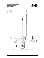
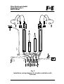
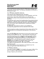
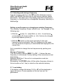
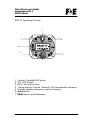
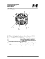
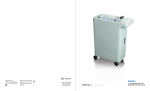
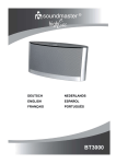
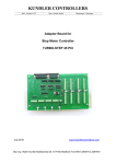
1
Filser Electronic GmbH
Gewerbestraße 2
86875 Waal
ATR 57 COM
VHF Transceiver
Installation
and
User manual
Ver. 1.6, Date: January 04
Page 1
Filser Electronic GmbH
Gewerbestraße 2
86875 Waal
Contents
1 GENERAL INFORMATION .......................................................4
1.1
Introduction ......................................................................4
1.2 Purpose of this equipment ...................................................4
1.3 Specification ..........................................................................5
1.4 Manufacturer..........................................................................5
2 INSTALLATION.........................................................................6
2.1 General ...................................................................................6
2.2 Pre-installation check ...........................................................6
2.3 Mechanical Panel installation ..............................................6
2.4 Installation wiring..................................................................6
2.5 Microphone connection ........................................................7
2.5.1 Microphone level check ...................................................7
2.6 Intercom mode.......................................................................8
2.7 Antenna Installation ..............................................................8
3 OPERATION INSTRUCTIONS...............................................12
3.1 Turn on .................................................................................12
3.2 Volume control ....................................................................12
3.3 Squelch level control ..........................................................12
3.4 VOX level control for Intercom...........................................13
3.5 Selecting a frequenzy......... Fehler! Textmarke nicht definiert.
3.6 Storing a frequency.............................................................14
3.7 Low-battery ..........................................................................14
Page 2
Filser Electronic GmbH
Gewerbestraße 2
86875 Waal
3.8 Automatic frequency control..............................................15
3.9 Transmitting mode ..............................................................15
3.10 Receiving indication .........................................................15
EuroCAE EC-Type Approval Certificate Ecanadian Certificate
......................................................................................................18
EC-Type Approval Certificate Ecanadian Certificate ..............19
Ecanadian Certificate.................................................................20
Page 3
Filser Electronic GmbH
Gewerbestraße 2
86875 Waal
1
General Information
1.1 Introduction
This ATR 57 manual is a description of the VHF Communication
transceiver in 3 parts:
1. General Information
2. Installation
3. Operating Instructions
1.2 Purpose of this equipment
The Filser ATR 57 is a VHF Communication transceiver covering
the aeronautical radio frequency range from 118,00MHz to
136,975 MHz in 25 KHz increments with 760 channels.
The ATR 57 was developed to meet all operational requirements
encountered in VFR flying. The Communication transceiver is
designed as a single block unit with 57mm diameter for instrument
panel or consul mounting. It is fastened by four (4mm) screws. All
controls and indicating displays are located on the front panel. On
the rear panel of the unit the connector (sub D9) for the aircraft
wiring is located. The VHF Antenna is connected to the BNC
socket.
The volume and squelch level can be selected easily.
The Unit can memorize 9 VHF frequencies for faster access in
operation. The Filser ATR 57 also contains a special intercom
facility controlled by VOX (Voice Operated X-mission). This is a
voice level controlled switch for the headset to turn off the
background while no speaking. For good VOX performance
identical Microphones should be used in order to guarantee the
same input level.
Two Microphones , two Headphones and an additional speaker
can be connected to the unit. For Intercom operation with a very
different microphones an optional Intercom switch can be installed
to turn off the background manually.
Page 4
Filser Electronic GmbH
Gewerbestraße 2
86875 Waal
1.3 Specification
Frequency range: 118,000 .... 136,975 MHz
Channels:
760
Channel spacing: 25 kHz
Modulation:
AM DSB, 70% modulation
Operation modus: alternate talking on one frequency
HF-output power: > 1 Watt
NF-output power: 1 Watt
Voltage:
10,5 V up to 16 V
Current consumption:
receiving mode:100mA and
transmitting mode: 1A
Microphone level: 15 mV up to 1V (70% modulation)
Dimensions:
57 x 57 x 160 mm
Weight:
500 g
Certification:
Reg. TP 321 ZV 034
1.4 Manufacturer
Filser Electronic GmbH
Gewerbestrasse 2, 86875 Waal, GERMANY
Tel.: +49 8246/9699-0, Fax.: +49 8246/1049
email: [email protected]
Homepage: www.filser.de
Page 5
Filser Electronic GmbH
Gewerbestraße 2
86875 Waal
2
Installation
2.1 General
The installation of the ATR 57 VHF Communication transceiver
depends on the type of aircraft and equipment involved. The
instructions given in this chapter therefore apply only generally.
2.2 Pre-installation check
Prior to fitting the new VHF Communication transceiver in the
aircraft the equipment must be checked according to the following
procedure in order to determine transport damages.
Visual Inspection:
¾ scratches, corrosion, damaged paintwork
¾ scratches on the nameplate
¾ bend of or broken-off pins, mechanical damage to rotor
switches.
2.3 Mechanical Panel installation
The ATR 57 should be installed in a way that it can be seen and
used by the pilot without any problems. It is designed for
instrument panel or control panel installation in the aircraft. The
cut-out diameter for placing the ATR 57 in the panel is standard
57mm (see last page). The Unit is fixed in the panel by four (4mm)
screws.
Avoid mounting the unit near hot places. Otherwise the unit will
need external cooling.
2.4 Installation wiring
Make sure that the room for the installation of the necessary wiring
and switches is sufficient.
The cable harness should be as short as possible. Avoid that
cables run near strong RF noise sources like the ignition coil,
generator, battery charger or anti-collision lights. This can cause a
additional noise in the speaker.
The ATR57 has to be protected by an external slow fuse with 2
Ampere
Page 6
Filser Electronic GmbH
Gewerbestraße 2
86875 Waal
The installation wiring diagrams demonstrate the wiring for single
(Fig. 1) and double microphone (Fig. 2) installation with and
without Intercom and Headphones.
Your service company can provide all needed cables, the
connectors are delivered with your ATR 57.
2.5 Microphone connection
The ATR57 has two microphone inputs :Mic 1 and Mic 2.
¾ Mic. 1 input for Electret microphone or dynamic
microphone with preamplifier (50 mV to 2Vpp adjustable
with the Mic. Level control). This input provides a bias
voltage of 9V at 330 Ohm. For dynamic microphone a
switch (Mic. Setting) located at the top side of the unit (see
diagram below) is used to select the input level for 5mV to
10mV without the bias voltage .
Factory setting is Electret.
¾ Mic 2 input is for Electret microphone only (50 mV to 2Vpp)
adjustable with the Mic Level control.
The Mic Level control is located at the top of the unit.
If two Electret microphone are used they must have identical
output levels for proper intercom operation, also the Mic Level
controls for Mic 1 and 2 are simultaneous.
Factory setting is standard Electret (ECM) microphone (50mV to
2V).
2.5.1 Microphone level check
¾ To get a reference for a correct MIC-level make sure that the
VOX-value is at 16. With a headset the level can be checked,
by speaking at the normal distance to the Mic. and increasing
the Mic. Level until the VOX turns on and off at a satisfying
level (preferably at high background noise)
45°
Mic. Level
Diagram for Mic Level and Mic Switch
Page 7
Filser Electronic GmbH
Gewerbestraße 2
86875 Waal
After installation in the aircraft is completed, a radio check
should be made and if necessary the Mic Level must be
readjusted.
2.6 Intercom mode
With Intercom two crew members can communicate over the ATR
57 system. This communication takes place only internally, there is
no transmission.
A special feature is the VOX (Voice Operated Transmission(x)).
The Intercom is opened only if one of the crew members is
speaking. This avoids having all the time surrounding noise on the
headphone.
The opening level for the VOX is adjusted as described in
paragraph 3.4.(VOX level control for intercom).
Only if the transmission key (PTT) is pressed, the radio will change
to the transmission mode. For best results microphones which
produce almost the same output level should be used. The use of
very different microphones can lead to the fact, that the member
with the lower output level can not open the VOX.
The best solution are identical amplified Electret-microphones.
The optional Intercom switch (for operation without VOX) must be
mounted externally. If it is not used the corresponding wire must be
connected (switched) to GND.
2.7 Antenna Installation
The ATR 57 requires a normal 50Ω-COM-antenna. Polarisation
must be vertical. Using a broad band COM-antenna provides a
high efficiency over the entire COM band. The antenna should
installed according to the manufacturers advises.
A 50Ω-coaxial wire (type RG 58) is to be used as an antenna wire.
Some important general advises for antenna installation are listed
below:
¾ Unsymmetrical antennas ( λ/4-Antenna), length 60 cm, should
be mounted on plane metal surfaces or metal plates of at least
50 x 50cm or more. This is not valid for λ/2-folded-up antennas
Page 8
Filser Electronic GmbH
Gewerbestraße 2
86875 Waal
¾ The antenna should have the maximal possible distance to
motor and propeller in order to avoid modulations on the signal.
¾ The COM-antenna should have the maximal possible distance
to the NAV-antenna in order to avoid interference on the
transmission.
Page 9
bl
ge
bl
Filser Electronic GmbH
Gewerbestraße 2
86875 Waal
bl
vi
bl
rt
Fig. 1
Installation wiring diagram for glider installation
Page 10
bl
ws
ws
g
e
bl
bl
bl
ge
bl
ge
vi
bl
rt
gn
bl
Aktiv when
closed
(Optional)
ge
(Optional)
Filser Electronic GmbH
Gewerbestraße 2
86875 Waal
Fig. 2
Installation wiring diagram for double installation with
intercom
Page 11
Filser Electronic GmbH
Gewerbestraße 2
86875 Waal
3 Operation Instructions
All elements necessary for the use of the transceiver are located in
the front side of the unit. The regulation of the various levels of the
headset microphones are located at the side of the unit (to be
adjusted once on the installation).
3.1 Turn on
The „ON-OFF“-switch (2) is positioned on the left side of the unit.
The radio is active, when the switch position is in „ON“ (upper
position).
3.2 Volume control
Push the VOL-SQ button once to get into the Volume mode
(Display shows VOL: 01 to 33). By turning the tuning knob (4) the
Volume can be varied. The Volume mode is left by selecting
another frequency by MEM or if the VOL-SQ button is pressed
again. The selected level is active until the ATR 57 is switched off.
To use this level as switch on default, push the STORE button (6)
while the Volume mode is active. For confirmation the ATR 57
shows „ST“ in its display.
3.3 Squelch level control
The squelch eliminates noise in case of missing reception signals.
On normal operation mode the squelch should be regulated in a
way that it eliminates noise of the receiver in case of no reception
signal. The normal level is between 1 and 2 (shown on the
display).
The higher the squelch level chosen, the more weak signals (far
away) are eliminated. In this way weak signals of transmissions on
the same frequency can be switched off.
Push the VOL-SQ button twice to get into the Squelch mode
(Display shows SQ: 01 to 16). By turning the tuning knob (4) the
Squelch setting can be varied. The Squelch mode is left by
selecting another frequency by MEM or if the VOL-SQ button is
pressed again. The selected level is active until the ATR 57 is
switched off. To use this level as switch on default, push the
STORE button (6) while the Squelch mode is active. For
confirmation the ATR 57 shows „ST“ in its display.
Page 12
Filser Electronic GmbH
Gewerbestraße 2
86875 Waal
The normal Squelch setting is about 3. With higher settings weak
signals may not be heard. The Squelch setting has no influence in
the intercom mode.
3.4 VOX level control for Intercom
VOX signifies Voice Operated trans–X-mission.
In this case it refers to the switching-on of the headsets, not to the
transmission. Task of the VOX-function is to eliminate the
background (cabine) noise during the Intercom mode while not
speaking.
An electronic switch opens the headsets when the selected volume
is reached. To assure correct function of this installation headsets
with nearly identical microphones should be used. Otherwise the
VOX level control can be substituted by a separately installed
intercom switch.
ATTENTION: If the Intercom switch is not installed the
corresponding signal wire must be connected to the mass.
Hand-microphones whose transmission buttons also switch off the
microphones are not meeting the requirements of the intercom
mode.
Push the VOL-SQ button three times to get into the Intercom mode
(Display shows VOX: 01 to 32). ). By turning the tuning knob (4)
the Intercom setting can be varied. The Intercom mode is left by
selecting another frequency by MEM or if the VOL-SQ button is
pressed again. The selected level is active until the ATR 57 is
switched off. To use this level as switch on default, push the
STORE button (6) while the Intercom mode is active. For
confirmation the ATR 57 shows „ST“ in its display.
The higher the selected level is, the louder you have to talk to open
the Intercom path.
Note: The Volume control described in 3.2 adjusts only the
received signal and not the Intercom level.
3.5 Memory selector
The memory selector MEM (7) is located in the upper middle of the
unit. It is used for selecting previous stored frequencies or for
saving a frequency (9 memories).
Page 13
Filser Electronic GmbH
Gewerbestraße 2
86875 Waal
3.6 Selecting and storing a frequency
Turn the memory selector in the SET position between memory
MEM1 and MEM9 (the white line on the memory selector shows
downward). The upper line of the display shows the actual active
frequency, in the second line a changeable frequency (stand-by) is
displayed >.
Setting a new Frequency or changing an existing Frequency
The standby Frequency (lower column) can be changed in the
following way:
¾ With the ↔ button (3 ) select MHz- or kHz . A small arrow >
on the display (9) shows to MHz- or kHz that can be changed
by the big frequency knob (4).
¾ With the ↑↓ button on the lower right side (5) this new
frequency can be activated. Now it is displayed on the upper
line, the old active frequency is deactivated and displayed in the
second line.
So it is possible to change the two frequencies by pushing one
button.
Storing a Frequency
Turn the memory selector MEM (7) to M 1... 9 where the new
frequency is to be stored. Factory setting of the memories are test
frequencies.
Between MEM 9 an 1 the unit is in set operation mode (as
described in 3.5)
By pressing the STORE button (6) the active frequency (shown in
the set mode on the 1.line) is stored on the selected memory.
3.7 Low-battery
If the battery voltage falls below 10,5V a „B“ will be displayed in
upper left corner. A save operation of the unit can not be
guaranteed.
Page 14
Filser Electronic GmbH
Gewerbestraße 2
86875 Waal
3.8 Automatic frequency control
If the actual used frequency has an intolerable frequency drift a "-"
(12) will appear in the upper right corner of the display. The
transmission mode then can not be activated.
In this case the ATR 57 is not working properly and must be
returned to the manufacturer.
Notice: Sometimes the "-" may be displayed, but it disappears
when the frequency is changed or the device is switched off and
on. This can be due to strong noise from outside the ATR 57. This
is no malfunction of the ATR 57
3.9 Transmission mode
By using the transmitting key (PTT), the ATR 57 will change to the
transmission mode on the frequency shown on the upper position
of the display. As long as the transmission takes place a "T" will be
shown instead of the decimal point between the MHz- and kHzvalue of the actual frequency (upper line), to control the proper
function of the device. By checking the Side-tone in the headphone
you have a further control for a proper transmission.
3.10 Receiving indication
As long as a receiving signal takes place or the squelch is open a
"R" will be shown instead of the decimal point between the MHzand kHz-value of the actual frequency (upper line).
Page 15
Filser Electronic GmbH
Gewerbestraße 2
86875 Waal
ATR 57 Operating Controls
7
1
6
2
3
5
4
1.
2.
3.
4.
5.
6.
7.
Volume / Squelch/VOX button
ON / OFF switch
MHz / kHz push-button
Tuning-knob for Volume, Squelch, VOX and standby frequency
Change standby frequency to active frequency
Store-button
MEM Select stored frequency
Page 16
Filser Electronic GmbH
Gewerbestraße 2
86875 Waal
ATR 57 Display
13
12
8
9
11
10
8. "B" Low-Battery display, shown when voltage is < 10,5V
9. "><" changing MHz or kHz range
10.
MHz-range of standby frequency
11.
kHz-range of standby frequency
12.
"-" shown at lost of transmitting or
receiving frequency (active frequency)
13.
"T" shown during transmitting mode
and
"R" shown during receiving mode (active frequency)
Page 17
Filser Electronic GmbH
Gewerbestraße 2
86875 Waal
EuroCAE
Page 18
Filser Electronic GmbH
Gewerbestraße 2
86875 Waal
EC-Type Approval Certificate
Page 19
Filser Electronic GmbH
Gewerbestraße 2
86875 Waal
Ecanadian Certificate
Page 20
Filser Electronic GmbH
Gewerbestraße 2
86875 Waal
Page 21