1
Operation Manual EDP Handling Systems As of: 2014-07-21 Subject to modifications. ©e.p.s. GmbH – Gewerbestraße 11 – D- 78739 Hardt - Tel.: +49 (0) 7422/ 56003-0 Registered office of the company: D-78739 Hardt, CEO: Dipl Ing. (FH) Bernhard Moosmann, HRB 480966 Stuttgart 1 as of: 2014-07-21 1 Contents 1 2 3 Contents .................................................................................................................................... 2 Introduction................................................................................................................................ 5 Safety Guidelines ...................................................................................................................... 6 3.1 General Safety Guidelines .................................................................................................. 6 3.2 Regard the Hints in the Operation Manual! ......................................................................... 6 3.3 Protection Against Dangerous Movements ......................................................................... 7 3.4 Explanations of Symbols and Hints .................................................................................... 7 3.4.1 Warning hints ............................................................................................................... 7 3.4.2 Symbols ....................................................................................................................... 7 4 Product Description ................................................................................................................... 8 4.1 Intended Use ...................................................................................................................... 8 4.2 Warranty and Liability ......................................................................................................... 8 4.3 Systems .............................................................................................................................. 9 4.3.1 EDP mini ...................................................................................................................... 9 4.3.2 EDP standard ............................................................................................................. 11 4.3.3 EDP maxi ................................................................................................................... 13 4.3.4 EDP Portal standard................................................................................................... 15 4.3.5 EDP Portal maxi ......................................................................................................... 17 4.3.6 EDP standard XYZ ..................................................................................................... 19 4.3.7 EDP maxi XYZ ........................................................................................................... 21 4.3.8 Area Gantry, Hanging................................................................................................. 23 4.3.9 Area Gantry, Latarally ................................................................................................ 25 4.4 Modules ............................................................................................................................ 27 4.4.1 Linear Module EDM 20P ............................................................................................ 27 4.4.2 Linear Axis EDM20EL ................................................................................................ 28 4.4.3 Linear Axis SM20EL ................................................................................................... 29 4.4.4 Linear Module EDM25................................................................................................ 30 4.4.5 Linear Axis EDM25EL ................................................................................................ 31 4.4.6 Linear Axis EDM25ES ................................................................................................ 32 4.4.7 Linear Axis EDM30EL ................................................................................................ 33 4.4.8 Portal Axis PM20EL ................................................................................................... 34 4.4.9 Portal Axis PM25EL ................................................................................................... 35 4.4.10 Portal Axis PM30EL ................................................................................................... 36 4.4.11 Place Unit SE20-E...................................................................................................... 37 Control Block EDS standard and maxi .................................................................................... 38 4.4.12 Control Block EDS 20................................................................................................. 39 4.4.13 Quick Change Unit ESW 20 ....................................................................................... 40 5 Assembly ................................................................................................................................. 43 6 Connection .............................................................................................................................. 45 6.1 Power Supplies ................................................................................................................. 45 6.2 Axis Control E12x0 ........................................................................................................... 46 6.3 Axis Control E11x0 ........................................................................................................... 48 6.4 Axis Control B1100 ........................................................................................................... 50 Subject to modifications. ©eps. GmbH – Gewerbestraße 11 – D- 78739 Hardt - Tel.: +49 (0) 7422/ 56003-0 Registered office of the company: D-78739 Hardt, CEO: Dipl Ing. (FH) Bernhard Moosmann, HRB 480966 Stuttgart 2 as of: 2014-07-21 6.5 Pin Assignment and Electrical Connection Data of the Motor ........................................... 52 6.5.1 Motor Plug EDM 20EL, EDM 25EL ............................................................................ 52 6.5.2 Motor Plug EDM25ES, SE30E, SE40E ...................................................................... 52 6.5.3 Motor Plug SE20E ...................................................................................................... 53 6.5.4 Motor Plug PM25/PM30 ............................................................................................. 53 6.6 Pin Assignment Motor Cable ............................................................................................ 54 6.6.1 Plug Controller Power Option standard ...................................................................... 54 6.6.2 Plug Controller Power Option HC, XC and UC ........................................................... 54 6.7 Pin Assignment ext. Distance Measurement System........................................................ 55 6.7.1 Plug ext. Distance Measurement System MSK500 .................................................... 55 6.7.2 Plug ext. Distance Measurement System LE100 (for safely reduced speed) ............. 55 6.8 Pin Assignment Encoder SE20E ...................................................................................... 56 6.9 Plug Sizes ......................................................................................................................... 57 Control Block EDS 20 ................................................................................................................. 58 6.9.1 Pin Assignment .......................................................................................................... 59 6.10 Control Block EDS standard and maxi .............................................................................. 60 6.10.1 Pin Assignment .......................................................................................................... 61 6.11 Power Strip ....................................................................................................................... 63 7 Commissioning ........................................................................................................................ 64 7.1 Setting the Speeds at the Electrical Axes ......................................................................... 64 7.2 Teaching of Positions at the Electrical Axes ..................................................................... 68 7.3 Stroke Adjustment EDM 20P ............................................................................................ 69 7.4 Stroke Adjustment EDM25 ................................................................................................ 70 7.5 Damping settings at the pneumatic modules .................................................................... 71 7.6 Adjusting Speed at the Pneumatic Modules ..................................................................... 71 7.7 Adjustment of the Switching Distances ............................................................................. 72 7.7.1 External Distance Measurement System ...............Fehler! Textmarke nicht definiert. 7.7.2 Reference Sensor at Electrical Axes .......................................................................... 73 7.7.3 End Position Sensor at Pneumatic Modules .............................................................. 73 8 Maintenance ............................................................................................................................ 74 8.1 After Commissioning ......................................................................................................... 74 8.2 Quarterly ........................................................................................................................... 75 9 Repairs .................................................................................................................................... 77 9.1 Change Sensors EDM20P Vertical ................................................................................... 78 9.2 Change of Sensors EDM25 .............................................................................................. 79 9.3 Adjustment of Sensor EDM25 ........................................................................................... 79 9.4 Readjust the Guidance EDM25, EDM25EL, EDM25ES.................................................... 80 10 Components- / Spare Parts Lists ............................................................................................. 81 10.1 Motors Overview ............................................................................................................... 81 10.2 Spare Parts for EDM20P .................................................................................................. 84 10.3 Spare Parts for EDM20EL ................................................................................................ 84 10.4 Spare Parts for SM20EL ................................................................................................... 84 10.5 Spare Parts for EDM30EL ................................................................................................ 84 10.6 Spare Parts for EDM25 ..................................................................................................... 84 10.7 Spare Parts for EDM25EL ................................................................................................ 84 10.8 Spare Parts for EDM25ES ................................................................................................ 85 Subject to modifications. ©eps. GmbH – Gewerbestraße 11 – D- 78739 Hardt - Tel.: +49 (0) 7422/ 56003-0 Registered office of the company: D-78739 Hardt, CEO: Dipl Ing. (FH) Bernhard Moosmann, HRB 480966 Stuttgart 3 as of: 2014-07-21 10.9 Spare Parts for PM20EL ................................................................................................... 85 10.10 Spare Parts for PM25EL/PM30EL .................................................................................... 85 10.11 Spare Parts for SE20 ........................................................................................................ 85 10.12 Spare Parts for SE30/40 ................................................................................................... 86 10.13 Motor Cable ...................................................................................................................... 86 10.14 Axis Control ...................................................................................................................... 87 10.15 Control Block .................................................................................................................... 87 10.16 Distance Measurement System ........................................................................................ 88 10.17 MagSpring ........................................................................................................................ 88 11 Disposal Hints ......................................................................................................................... 89 12 Assembly Instruction according to Annex VI (EC-Directive 006/42/EC) .................................. 90 13 Declaration of Incorporation for Incomplete Machines (EC-Directive 2006/42/EC) ................. 91 14 Risk Assessment (EG Directive 2006/42/EC) .......................................................................... 92 Subject to modifications. ©eps. GmbH – Gewerbestraße 11 – D- 78739 Hardt - Tel.: +49 (0) 7422/ 56003-0 Registered office of the company: D-78739 Hardt, CEO: Dipl Ing. (FH) Bernhard Moosmann, HRB 480966 Stuttgart 4 as of: 2014-07-21 2 Introduction With our EDM modules we have provided an essential step towards reaching short cycle times. This operation manual is subject to our efforts to present all important information in a short and understandable way. If there are still any questions left, please, do not hesitate to contact us. We will also appreciate your suggestions. We wish you great success in integrating our devices to your machines or plants. Subject to modifications. ©eps. GmbH – Gewerbestraße 11 – D- 78739 Hardt - Tel.: +49 (0) 7422/ 56003-0 Registered office of the company: D-78739 Hardt, CEO: Dipl Ing. (FH) Bernhard Moosmann, HRB 480966 Stuttgart 5 as of: 2014-07-21 3 Safety Guidelines 3.1 General Safety Guidelines The pick-and-place devices EDP are built state-of-the-art and according to the acknowledged safetyrelated rules, and they should only be used for the intended purpose and in perfect condition concerning safety. 3.2 Regard the Hints in the Operation Manual! It is a condition for the safe operation and an operation free of any disturbances of the pick-and-place devices EDP to know the basic safety instructions. Each person dealing with the assembly, commissioning, maintenance and operation of the pick-andplace devices EDP must have read and understood the complete user manual, especially the chapter about the safety guidelines. Additionally, the rules and instructions for accident prevention (UVV) valid at the place of action / operation have to be regarded. In case of improper use dangers for life and health of the users or a third party respectively impairments of the plant or other material assets might occur. In any case of disturbances which might effect the safety the plant has to be stopped immediately and saved against a restart. Afterwards the disturbance has to be abolished immediately. All works at the devices have to be executed under pressure- and power- free condition. For the operation of the devices the user must provide protective covers, safety doors or other safety precautions which comply with the usual safety guidelines and safety norms which prevent the presence of persons in the working room the devices are placed during their operation. The devices may principally only be set into operation when the protections are closed Subject to modifications. ©eps. GmbH – Gewerbestraße 11 – D- 78739 Hardt - Tel.: +49 (0) 7422/ 56003-0 Registered office of the company: D-78739 Hardt, CEO: Dipl Ing. (FH) Bernhard Moosmann, HRB 480966 Stuttgart 6 as of: 2014-07-21 3.3 Protection Against Dangerous Movements Dangerous movements can occur when drives are started inaccurately. The drive parts are controlled in a way that a malfunction can mainly be excluded. Although, due to reasons of personal protection, the danger of injuries as well as of dangers to damage material it may not solely be trusted upon that. Until in-built controls get effective, incorrect drive movements have to be expected. 3.4 Explanations of Symbols and Hints For the quick understanding of this instruction and the safe handling of the EDM- modules, the following warning hints and symbols are used: 3.4.1 Warning hints ! Danger This symbol refers to a directly threatening danger which can – if the safety regulations are not regarded – lead to the death or a personal injury. ! Warning This symbol refers to a possibly threatening danger which can – if the safety regulations are not regarded – lead to personal injury or serious material damages. ! Attention This symbol refers to a possibly threatening danger which can – if the safety regulations are not regarded – lead to material damages. 3.4.2 Symbols INFO Information hint This symbol stands for information that contributes to a better understanding. Subject to modifications. ©eps. GmbH – Gewerbestraße 11 – D- 78739 Hardt - Tel.: +49 (0) 7422/ 56003-0 Registered office of the company: D-78739 Hardt, CEO: Dipl Ing. (FH) Bernhard Moosmann, HRB 480966 Stuttgart 7 as of: 2014-07-21 4 Product Description 4.1 Intended Use The pick-and-place devices EDP are used in automation systems and are only applied for the movement of work pieces. The pneumatic modules are only purposed for an operation by means of compressed air (4.7 bar). Each other use extending this is regarded as use other than for the intended purpose. The electrical axes are solely purposed for the operation with original LinMot components (controller, cable …). Each other use extending this is regarded as use other than for the intended purpose. The compliance with the specified assembly - and dismantling instruction, the maintenance - and repair conditions as well as the compliance with the specifications given in the data sheets also belong to the intended use. 4.2 Warranty and Liability Principally, the “General Sales and Delivery Conditions“ of e·p·s GmbH are applied. Warranty- and liability claims in regard of personal or material damages are excluded if they are related to one or several of the following causes: Use outside the intended use Improper assembly, start-up and maintenance If work pieces are moved manually while the power supply is connected Running of the pick-and-place devices EDP with defective and/or inoperable safety - and protection facilities Disregarding the hints in the operation manual regarding assembly, commissioning, operation and maintenance Non-observance of the EG- machines directive, the Accident Prevention Regulations (UVV), the VDE guideline as well as of the safety - und assembly hints Unauthorized changes of the construction Deficient supervision of wear parts Improperly executed repairs Disaster situations caused by influence of foreign objects and force majeur Unless otherwise agreed, the warranty is in effect for 15 months from the date of delivery on in case of intended use in one-shift operation and under compliance of the specified maintenance- and lubrication intervals. Subject to modifications. ©eps. GmbH – Gewerbestraße 11 – D- 78739 Hardt - Tel.: +49 (0) 7422/ 56003-0 Registered office of the company: D-78739 Hardt, CEO: Dipl Ing. (FH) Bernhard Moosmann, HRB 480966 Stuttgart 8 as of: 2014-07-21 4.3 Systems 4.3.1 EDP mini Description With the EDP mini, a very compact and, with 40 mm construction width, very slim handling is made available which is alternatively driven by a linear motor or pneumatically. Concerning short cycle times, the linear motor handling is by far superior to all pneumatic systems at the points of efficiency, energy consumption, maintenance cycles and life cycle. Simple processes with less demanding cycle times can also be realized with the structurally identical pneumatic modules EDM 20 P. Due to the small construction width of only 40mm, the EDP mini needs few space. The EDP is delivered ready for operation and completely mounted. Advantages: up to 120 cycles per minute only 40 mm wide up to 3 kg useful load very high durability low energy consumption of the linear modules CAD models are immediately available due to the handling configurator Technical Data Drive method Stroke horizontal (Y) Stroke vertical (Z) Maximum speed Peak force Permanent force Repeatability with external distance measurement system (5µm) Control block with 5/3, 5/2 or vacuum units EDM 20 P pneumatic 50,100 mm 50,100 mm 1,5m/s 180N 180N +/-0,05mm up to 6 valves EDM 20 EL electrical, linear motor 50 mm 50 mm 6,8m/s 67N 15N +/-0,05mm +/-0,02mm Permissible torques at the gripper flange Torques EDP mini 50/xxx EDP mini 100/xxx EDP mini 200/xxx EDP mini 300/xxx Tx 25Nm 25Nm 50Nm 50Nm Ty 5Nm 5Nm 5Nm 5Nm 100,200,300 mm 100,200,300 mm 4,8m/s 137N 31N +/-0,05mm +/-0,02mm Useful load (centric) Stroke Y 50mm 100mm Stroke Z 50mm 3kg 3kg 100mm 3kg 2kg 200mm 2kg 1kg 300mm 1kg - 200mm 300mm 2kg 1kg - 1kg 0,5kg - Tz 5Nm 5Nm 5Nm 5Nm Subject to modifications. ©eps. GmbH – Gewerbestraße 11 – D- 78739 Hardt - Tel.: +49 (0) 7422/ 56003-0 Registered office of the company: D-78739 Hardt, CEO: Dipl Ing. (FH) Bernhard Moosmann, HRB 480966 Stuttgart 9 as of: 2014-07-21 Subject to modifications. ©eps. GmbH – Gewerbestraße 11 – D- 78739 Hardt - Tel.: +49 (0) 7422/ 56003-0 Registered office of the company: D-78739 Hardt, CEO: Dipl Ing. (FH) Bernhard Moosmann, HRB 480966 Stuttgart 10 as of: 2014-07-21 4.3.2 EDP standard Description The pick & place devices EDP are based on EDM linear units. These linear units were especially developed to reach short cycle times. The pick & place device EDP standard consists of the following drive units: EDM 25 - horizontal linear unit (electrical or pneumatic) EDM 20 - vertical linear unit (electrical or pneumatic) EDS – control block Advantages: free choice between electrical or pneumatic linear units compact, ready for operation construction quick setup very simple stroke adjustment simple adjustment of speeds via exhaust air throttles at the control block low wear because of doing without dampers safe cable- and hose duct with warranty many options Technical Data Drive method Stroke horizontal (Y) EDM 25 pneumatic 60,100,160,200, 260,300,360mm 1,5m/s 280N 280N +/-0,05mm - EDM 25 EL electrical, linear motor 100,200,300,360mm EDM 20 pneumatic - EDM 20 EL electrical, linear motor - Stroke vertical (Z) 50,100 mm 50 mm 100,200,300 mm Maximum speed 4,8m/s 1,5m/s 6,8m/s 4,8m/s Peak force 137N 180N 67N 137N Permanent force 31N 180N 15N 31N Repeatability +/-0,05mm +/-0,05mm +/-0,05mm +/-0,05mm with external distance measurement +/-0,02mm +/-0,02mm +/-0,02mm system (5µm) Control block with 5/3, 5/2 or vacuum units up to 6 valves Instead of the EDM 25 EL the EDM 30 EL can be applied alternatively. Please, regard the technical data of this module on page 33 in this case. Permissible torques at the gripper flange Useful load (centric) Stroke Y 60mm 100mm Stroke Z 50mm 4kg 4kg 100mm 4kg 4kg 200mm 4kg 3kg 300mm 1kg 2kg Torques EDP mini 50/xxx EDP mini 100/xxx EDP mini 200/xxx EDP mini 300/xxx Tx 25Nm 25Nm 50Nm 50Nm Ty 5Nm 5Nm 5Nm 5Nm 160mm 200mm 260mm 300mm 360mm 4kg 4kg 3kg 2kg 4kg 3kg 2kg 1kg 4kg 3kg 2kg 1kg 3kg 2kg 1kg 0,5kg 2kg 1kg 0,5kg 0,5kg Tz 5Nm 5Nm 5Nm 5Nm Subject to modifications. ©eps. GmbH – Gewerbestraße 11 – D- 78739 Hardt - Tel.: +49 (0) 7422/ 56003-0 Registered office of the company: D-78739 Hardt, CEO: Dipl Ing. (FH) Bernhard Moosmann, HRB 480966 Stuttgart 11 as of: 2014-07-21 Measurement Type EDM 25-60 EDM 25-100 EDM 25-160 EDM 25-200 EDM 25-260 EDM 25-300 EDM 25-360 EDM 20-50 EDM 20-100 EDM 20-200 EDM 20-300 A pneumatic 216 371 371 471 471 571 571 - B electrical linear motor 297 378 507 607 - Subject to modifications. ©eps. GmbH – Gewerbestraße 11 – D- 78739 Hardt - Tel.: +49 (0) 7422/ 56003-0 Registered office of the company: D-78739 Hardt, CEO: Dipl Ing. (FH) Bernhard Moosmann, HRB 480966 Stuttgart pneumatic 230 300 - 12 electrical linear motor 193 286 366 496 as of: 2014-07-21 4.3.3 EDP maxi Description The EDP Portal high dynamics due to its very dynamic linear motor in the x-axis and the light weight z-axis and thus very short cycle times even at long strokes. The horizontal linear unit is built electrically, the vertical unit is built either electrically or pneumatically on demand. Advantages: high dynamics in the x- and z-direction short cycle times at long travel ways high precision by means of an optional distance measurement system compact construction various options Technical Data EDM 25 EDM 25 EL Drive method pneumatic electrical, linear motor Stroke horizontal (Y) 60,100,160,200,260,300,360mm 100,200,300,360mm Stroke vertical (Z) 60,100,160,200,260,300,360mm 100,200,300,360mm Maximum speed 1,5m/s 4,8m/s Peak force 280N 137N Permanent force 280N 31N Repeatability +/-0,05mm +/-0,05mm with external distance measurement +/-0,02mm system (5µm) Control block with 5/3, 5/2 or vacuum units up to 6 valves Instead of the EDM 25 EL the EDM 30 EL can be applied alternatively. Please, regard the technical data of this module on page 33 in this case. Permissible torques at the gripper flange Torques Tx 50Nm Ty 5Nm Useful load (centric) Stroke Y 60mm 100mm Stroke Z 60mm 5kg 5kg 100mm 5kg 5kg 160mm 5kg 5kg 200mm 5kg 4kg 260mm 5kg 4kg 300mm 4kg 3kg 360mm 4kg 3kg 160mm 200mm 260mm 300mm 360mm 5kg 5kg 5kg 4kg 4kg 3kg 3kg 4,5kg 4kg 4kg 3kg 3kg 2kg 2kg 4,5kg 4kg 4kg 3kg 3kg 2kg 2kg 3kg 3kg 3kg 2kg 2kg 1kg 1kg 3kg 3kg 3kg 2kg 2kg 1kg 1kg Tz 5Nm Subject to modifications. ©eps. GmbH – Gewerbestraße 11 – D- 78739 Hardt - Tel.: +49 (0) 7422/ 56003-0 Registered office of the company: D-78739 Hardt, CEO: Dipl Ing. (FH) Bernhard Moosmann, HRB 480966 Stuttgart 13 as of: 2014-07-21 Measurement Type EDM 25-60 EDM 25-100 EDM 25-160 EDM 25-200 EDM 25-260 EDM 25-300 EDM 25-360 A pneumatic 216 371 371 471 471 571 571 Electrical linear motor 297 378 507 607 Subject to modifications. ©eps. GmbH – Gewerbestraße 11 – D- 78739 Hardt - Tel.: +49 (0) 7422/ 56003-0 Registered office of the company: D-78739 Hardt, CEO: Dipl Ing. (FH) Bernhard Moosmann, HRB 480966 Stuttgart 14 as of: 2014-07-21 4.3.4 EDP Portal standard Description The EDP Portal high dynamics due to its very dynamic linear motor in the x-axis and the light weight z-axis and thus very short cycle times even at long strokes. The horizontal linear unit is built electrically, the vertical unit is built either electrically or pneumatically on demand. Advantages: high dynamics in the x- and z-direction short cycle times at long travel ways high precision by means of an optional distance measurement system compact construction various options Technical Data Drive method Stroke horizontal (X) Stroke vertical (Z) Maximum speed Peak force Permanent force Repeatability -with external distance measurement system (5 ) Control block with 5/3, 5/2 or vacuum units PM 25 EL electrical, linear motor 90,1450mm*2 150,250,350,450,550,650,750 950,1150,1350mm*1 3,5m/s² 255N 51N ± 0.05mm ± 0.02mm EDM 20 P pneumatic - EDM 20 EL Electrical, linear motor - 50, 100mm 1.5m/s 180N 180N ± 0.05mm - 50mm 6.8m/s 67N 15N ± 0.05mm ± 0.02mm 100, 200, 300mm 4.8m/s 137N 31N ±0.05mm ±0.02mm up to 6 valves up to 6 valves up to 6 valves up to 6 valves *1 with wiper – 20mm stroke *2 only without wiper Permissible torques at the gripper flange Useful load (centric) Stroke X all strokes Stroke Z 50 mm 4kg 100 mm 4kg 200 mm 4kg 300 mm 3kg Torques EDM 20-50 EDM 20-100 EDM 20-200 EDM 20-300 Tx 25Nm 25Nm 50Nm 50Nm Ty 25Nm 25Nm 25Nm 25Nm Tz 5Nm 5Nm 5Nm 5Nm Subject to modifications. ©eps. GmbH – Gewerbestraße 11 – D- 78739 Hardt - Tel.: +49 (0) 7422/ 56003-0 Registered office of the company: D-78739 Hardt, CEO: Dipl Ing. (FH) Bernhard Moosmann, HRB 480966 Stuttgart 15 as of: 2014-07-21 Measurement Type PM 25-xxx EDM 20-50 EDM 20-100 EDM 20-200 EDM 20-300 L electrical linear motor stroke + 270 - B pneumatic 230 300 - C electrical linear motor 193 286 366 496 Subject to modifications. ©eps. GmbH – Gewerbestraße 11 – D- 78739 Hardt - Tel.: +49 (0) 7422/ 56003-0 Registered office of the company: D-78739 Hardt, CEO: Dipl Ing. (FH) Bernhard Moosmann, HRB 480966 Stuttgart 16 without wiper 45 45 45 45 45 with wiper 57 57 57 57 57 as of: 2014-07-21 4.3.5 EDP Portal maxi Description The EDP Portal maxi transports high useful loads on long distances with high dynamics. Opposite to the light z-axis of the Portal standard, the EDM 25 is operated in its pneumatic or electronic execution with linear motor or shaft. Advantage: high dynamics even with bigger useful loads rigid construction robust execution Technical Data Drive method Stroke horizontal (X) Stroke vertical (Z) Maximum speed Peak force Permanent force Repeatability -with external distance measurement system (5µm) Control block with 5/3, 5/2 or vacuum units PM 25 EL electrical, linear motor 90, 1450*2mm 150, 250, 350, 450, 550, 650, 750, 950, 1150, 1350*1mm 3.5m/s 255N 51N ± 0.05mm ± 0.02mm EDM 25 pneumatic - EDM 25 EL electrical, linear motor - 60, 100, 160, 200, 260, 300, 360mm 1.5m/s 280N 280N ± 0.05mm - 100, 200, 300mm 4.8m/s 137N 31N ± 0.05mm ±0.02mm up to 6 valves up to 6 valves up to 6 valves Instead of the EDM 25 EL the EDM 30 EL can be applied alternatively. Please, regard the technical data of this module on page 33 in this case. Useful load (centric) Stroke X all strokes Stroke Y 60 mm 5kg 100 mm 5kg 160 mm 4kg 200 mm 4kg 260 mm 3kg 300 mm 3kg 360 mm 2kg Permissible torques at the gripper flange Torques Subject to modifications. ©eps. GmbH – Gewerbestraße 11 – D- 78739 Hardt - Tel.: +49 (0) 7422/ 56003-0 Registered office of the company: D-78739 Hardt, CEO: Dipl Ing. (FH) Bernhard Moosmann, HRB 480966 Stuttgart 17 Tx 50 Nm Ty 25 Nm as of: 2014-07-21 Tz 25Nm Measurement Type PM 25-xxx EL EDM 25-60 EDM 25-100 EDM 25-160 EDM 25-200 EDM 25-260 EDM 25-300 EDM 25-360 L electrical linear motor stroke + 270 - B pneumatic 216 371 371 471 471 571 571 C electrical linear motor 297 378 507 - Subject to modifications. ©eps. GmbH – Gewerbestraße 11 – D- 78739 Hardt - Tel.: +49 (0) 7422/ 56003-0 Registered office of the company: D-78739 Hardt, CEO: Dipl Ing. (FH) Bernhard Moosmann, HRB 480966 Stuttgart 18 without wiper 45 45 45 45 45 45 45 45 with wiper 57 57 57 57 57 57 57 57 as of: 2014-07-21 4.3.6 EDP standard XYZ Description With the EDP standard XYZ, a very dynamic 3-axes handling system is made available. Due to its scalable strokes and the free choice between electrical und pneumatic drive units, the EDP standard XYZ adjusts to your place of construction and your budget flexibly. With its optional c-axis, the system is a real alternative to a robot. Advantages: high dynamics high flexibility small space requirements due to scalable strokes optimal cost adjustment due to free choice of drive units - complete systems by rotation units, grippers, suckers and controls Technical Data Drive method Stroke horizontal (Y) PM 25 EL electrical, linear motor 90, 1450*2mm 150, 250, 350, 450, 550, 650, 750, 950, 1150, 1350*1mm - Stroke vertical (Z) - 60, 100, 160, 200, 260, 300, 360mm - Maximum speed Peak force Permanent force Repeatability -with external distance measurement system (5µm) Control block with 5/3, 5/2 or vacuum units 255N 51N ± 0.05mm ± 0.02mm 1.5m/s 280N 280N ± 0.05mm - 4.8m/s 137N 31N ± 0.05mm ±0.02mm 1.5m/s 180N 180N ± 0.05mm - 6.8m/s 67N 15N ± 0.05mm ± 0.02mm 100, 200, 300mm 4.8m/s 137N 31N ± 0.05mm ± 0.02mm up to 6 valves up to 6 valves up to 6 valves up to 6 valves up to 6 valves up to 6 valves Stroke horizontal (X) EDM 25 pneumatic EDM 20 P pneumatic EDM 20 EL electrical, linear motor - EDM 25 EL electrical, linear motor - - - - 100, 200, 300, 360mm - - - - 50, 100mm 50mm *1 with wiper – 20mm stroke *2 only deliverable without wiper Instead of the EDM 25 EL the EDM 30 EL can be applied alternatively. Please, regard the technical data of this module on page 33 in this case. Useful load (centric) Stroke Y 60 mm Stroke Z 50 mm 4kg 100 mm 4kg 200 mm 4kg 300 mm 3kg 100 mm 160 mm 200 mm 260 mm 300 mm 360 mm 4kg 4kg 3kg 2kg 4kg 4kg 3kg 2kg 4kg 3kg 2kg 1kg 4kg 3kg 2kg 1kg 3kg 2kg 1kg 0.5kg 2kg 1kg 0.5kg 0.5kg Permissible torques at the gripper flange Torques EDM 20-50 EDM 20-100 EDM 20-200 EDM 20-300 Tx 25Nm 25Nm 50Nm 50Nm Ty 10Nm 10Nm 10Nm 10Nm Subject to modifications. ©eps. GmbH – Gewerbestraße 11 – D- 78739 Hardt - Tel.: +49 (0) 7422/ 56003-0 Registered office of the company: D-78739 Hardt, CEO: Dipl Ing. (FH) Bernhard Moosmann, HRB 480966 Stuttgart Tz 5Nm 5Nm 5Nm 5Nm 19 as of: 2014-07-21 Measurement Type PM 25-xxx EL EDM 25-60 EDM 25-100 EDM 25-160 EDM 25-200 EDM 25-260 EDM 25-300 EDM 25-360 EDM 20-50 EDM 20-100 EDM 20-200 EDM 20-300 L electrical linear motor stroke + 270 - pneumatic B electrical linear motor without wiper 216 371 371 471 471 571 571 - 297 378 507 607 - 45 45 45 45 45 45 45 45 45 45 45 45 Subject to modifications. ©eps. GmbH – Gewerbestraße 11 – D- 78739 Hardt - Tel.: +49 (0) 7422/ 56003-0 Registered office of the company: D-78739 Hardt, CEO: Dipl Ing. (FH) Bernhard Moosmann, HRB 480966 Stuttgart 20 C with wiper 57 57 57 57 57 57 57 57 57 57 57 57 pneumatic 230 300 - D Electrical , linear motor 193 286 366 496 as of: 2014-07-21 4.3.7 EDP maxi XYZ Description The EDP maxi with its well-tried system of construction is complemented with an x-axis with linear motor. Besides the scalable strokes the system has a high stiffness for bigger useful loads. The standard construction works with the portal axis PM 25 EL as x-axis. For higher useful loads and longer cantilevers, the portal axis PM 30 EL is applied. The vertical linear drive can be executed pneumatically or electrically with linear motor or with shaft drive. Advantages: high useful load variable strokes big choice of linear units - diverse peripherals Technical Data Drive method Stroke horizontal (X) Stroke horizontal (Y) Stroke vertical (Z) Maximum speed Peak force Permanent force Repeatability -with external distance measurement system (5µm) Control block with 5/3, 5/2 or vacuum units PM 25 EL electrical, linear motor 90, 1450*2mm 150, 250, 350, 450, 550, 650, 750, 950, 1150, 1350*1mm 3.5m/s 255N 51N ± 0.05mm ± 0.02mm EDM 25 pneumatic - EDM 25 EL electrical, linear motor - 60, 100, 160, 200, 260, 300, 360mm 60, 100, 160, 200, 260, 300, 360mm 1.5m/s 280N 280N ± 0.05mm - 100, 200, 300, 36mm 100, 200, 300mm 4.8m/s 137N 31N ± 0.05mm ±0.02mm up to 6 valves up to 6 valves up to 6 valves Instead of the EDM 25 EL the EDM 30 EL can be applied alternatively. Please, regard the technical data of this module on page 33 in this case. Useful load (centric) Stroke Y 60 mm Stroke Z 60 mm 5kg 100 mm 5kg 160 mm 5kg 200 mm 5kg 260 mm 5kg 300 mm 4kg 360 mm 4kg 100 mm 160 mm 200 mm 5kg 5kg 5kg 4kg 4kg 3kg 3kg 5kg 5kg 5kg 4kg 4kg 3kg 3kg 4.5kg 4kg 4kg 3kg 3kg 2kg 2kg 260 mm 4.5kg 4kg 4kg 3kg 3kg 2kg 2kg 300 mm 360 mm 3kg 3kg 3kg 2kg 2kg 1kg 1kg 3kg 3kg 3kg 2kg 2kg 1kg 1kg Permissible torques at the gripper flange Torques Subject to modifications. ©eps. GmbH – Gewerbestraße 11 – D- 78739 Hardt - Tel.: +49 (0) 7422/ 56003-0 Registered office of the company: D-78739 Hardt, CEO: Dipl Ing. (FH) Bernhard Moosmann, HRB 480966 Stuttgart 21 Tx 50Nm Ty 25Nm as of: 2014-07-21 Tz 25Nm Measurement Type PM 25-xxx EL EDM 25-60 EDM 25-100 EDM 25-160 EDM 25-200 EDM 25-260 EDM 25-300 EDM 25-360 L electrical linear motor stroke + 270 - B pneumatic C electrical linear motor without wiper 45 45 45 45 45 45 45 45 Subject to modifications. ©eps. GmbH – Gewerbestraße 11 – D- 78739 Hardt - Tel.: +49 (0) 7422/ 56003-0 Registered office of the company: D-78739 Hardt, CEO: Dipl Ing. (FH) Bernhard Moosmann, HRB 480966 Stuttgart 22 D with wiper pneumatic 57 57 57 57 57 57 57 57 216 371 371 471 471 571 571 electrical, linear motor 297 378 507 607 as of: 2014-07-21 4.3.8 Area Gantry, Hanging Description Due to the centered position of the x-axis of the area gantry maxi, hanging version, a clearly longer y- traversing range can be realized. However, the stroke of the z-axis is limited because it moves under the x-axis. Opposite to the conventional construction of gantries with double x-axis no tensions between the axes can occur with the lateral and hanging construction methods. So both systems have a long life cycle and are easy to integrate. Advantages: large area by symmetrical construction high dynamics due to strong linear motors simple mounting Technical Data Drive method Stroke horizontal (X) PM 30 EL electrical, linear motor 170, 230, 320, 440, 530, 1820mm*1 150, 270, 360, 450, 570, 660, 870, 1050, 1260, 1470, 1650*1mm - Stroke vertical (Z) Maximum speed Peak force Permanent force Repeatability -with external distance measurement system (5µm) Control block with 5/3, 5/2 or vacuum units PM 25 EL electrical, linear motor - EDM 25 EL electrical, linear motor - - 2.5m/s 550N 145N ± 0.05mm ± 0.02mm 90mm*2, 150, 250, 350, 450, 550, 650, 750, 950mm*3 3.5m/s 255N 51N ± 0.05mm ± 0.02mm up to 6 valves up to 6 valves up to 6 valves 100, 200, 300mm 4.8m/s 137N 31N ± 0.05mm ±0.02mm *1 without wiper *2 only without wiper *3 with wiper- 20mm stroke Instead of the EDM 25 EL the EDM 30 EL can be applied alternatively. Please, regard the technical data of this module on page 33 in this case. Useful load (centric) Stroke Y 90 - 650mm Stroke Z 100mm 5kg 200mm 5kg 300mm 4kg 750mm 950mm 4kg 4kg 3kg 4kg 3kg 2kg Permissible torques at the gripper flange Torques Subject to modifications. ©eps. GmbH – Gewerbestraße 11 – D- 78739 Hardt - Tel.: +49 (0) 7422/ 56003-0 Registered office of the company: D-78739 Hardt, CEO: Dipl Ing. (FH) Bernhard Moosmann, HRB 480966 Stuttgart 23 Tx 50 Nm Ty 25 Nm as of: 2014-07-21 Tz 25Nm Measurement Type PM 30-xxx EL PM 25-xxx EL EDM 25-100 EL EDM 25-200 EL EDM 25-300 EL A electrical, linear motor stroke +370 +30 (for axes with wiper) - B C Electrical, linear motor - electrical, linear motor - stroke + 270 - 297 378 507 without wiper D 45 57 45 45 45 45 57 57 57 57 Subject to modifications. ©eps. GmbH – Gewerbestraße 11 – D- 78739 Hardt - Tel.: +49 (0) 7422/ 56003-0 Registered office of the company: D-78739 Hardt, CEO: Dipl Ing. (FH) Bernhard Moosmann, HRB 480966 Stuttgart E with wiper 24 as of: 2014-07-21 4.3.9 Area Gantry, Latarally Description The Area Gantry maxi lateral offers a very clear, big working space with very good accessibility. The portal axis PM 30 EL offers a very rigid base for the lateral cantilever with its allowed torque Tx of 250 Nm. Due to the strong linear motors the system offers a very high dynamics in the area. The vertical axis can be executed pneumatically or electrically according to your choice. Advantages: high dynamics rigid construction clear arrangement very good accessibility Technical Data Drive method Stroke horizontal (X) PM 30 EL electrical, linear motor 170, 230, 320, 440, 530, 1820mm*1 150, 270, 360, 450, 570, 660, 870, 1050, 1260, 1470, 1650*1mm - Stroke vertical (Z) Maximum speed Peak force Permanent force Repeatability -with external distance measurement system (5µm) Control block with 5/3, 5/2 or vacuum units PM 25 EL electrical, linear motor - EDM 25 EL electrical, linear motor - - 2.5m/s 550N 145N ± 0.05mm ± 0.02mm 90mm*2, 150, 250, 350, 450, 550, 650, 750, 950mm*3 3.5m/s 255N 51N ± 0.05mm ± 0.02mm up to 6 valves up to 6 valves up to 6 valves 100, 200, 300mm 4.8m/s 137N 31N ± 0.05mm ±0.02mm Instead of the EDM 25 EL the EDM 30 EL can be applied alternatively. Please, regard the technical data of this module on page 33 in this case. Permissible torques at the gripper flange Useful load (centric) Stroke Y 90 - 350mm Stroke Z 100mm 5kg 200mm 5kg 300mm 4kg 450mm 550mm 650mm 4kg 4kg 3kg 4kg 3kg 2kg 3kg 2kg 1kg Torques Subject to modifications. ©eps. GmbH – Gewerbestraße 11 – D- 78739 Hardt - Tel.: +49 (0) 7422/ 56003-0 Registered office of the company: D-78739 Hardt, CEO: Dipl Ing. (FH) Bernhard Moosmann, HRB 480966 Stuttgart 25 Tx 50 Nm Ty 25 Nm Tz 25Nm as of: 2014-07-21 Measurement Type PM 30-xxx EL PM 25-xxx EL EDM 25-100 EL EDM 25-200 EL EDM 25-300 EL A electrical, linear motor stroke +370 +30 (for axes with wiper) - B C Electrical, linear motor - electrical, linear motor - stroke + 270 - 297 378 507 without wiper D 45 57 45 45 45 45 57 57 57 57 Subject to modifications. ©eps. GmbH – Gewerbestraße 11 – D- 78739 Hardt - Tel.: +49 (0) 7422/ 56003-0 Registered office of the company: D-78739 Hardt, CEO: Dipl Ing. (FH) Bernhard Moosmann, HRB 480966 Stuttgart E with wiper 26 as of: 2014-07-21 4.4 Modules 4.4.1 Linear Module EDM 20P Technical Data Drive method Stroke Maximum speed Peak force Permanent force Useful load (centric) Repeatability Operating pressure Piston diameter Temperature range Net weight EDM 20-50 P pneumatic 50mm 1.5 m/s 180N 180N 4kg ± 0.02mm 4…7bar 20mm 0….50°C 0.9kg Hose bracket (optional for vertical module) EDM 20-100 P pneumatic 100mm 1.5m/s 180N 180N 4 kg ±0.02mm 4….7bar 20mm 0…50°C 1.1kg End position sensor retracted for vertical module for standard module Extend stroke adjustment End position sensor retracted for vertical module for standard module Retract air connection Extend damping Extend air connection Retract damping Fixation of the peripherals: 4x borehole with countersink for screw M4 (DIN/EN/ISO4762) and centering 9H7 ! Clamping stroke adjustment Retract stroke adjustment tellung einfahren Fixation of the module: Thread M4 depth 7 mm*1 and centering 9H7 Attention *1 Too long or short screws can lead to damages of the device or the peripherals. Subject to modifications. ©eps. GmbH – Gewerbestraße 11 – D- 78739 Hardt - Tel.: +49 (0) 7422/ 56003-0 Registered office of the company: D-78739 Hardt, CEO: Dipl Ing. (FH) Bernhard Moosmann, HRB 480966 Stuttgart 27 as of: 2014-07-21 4.4.2 Linear Axis EDM20EL Technical Data Drive method Stroke Maximum speed Peak force Permanent force Useful load (centric) Repeatability -with external distance measurement system (10µm) Temperature range Net weight Air purity class (ISO 14644-1) EDM 20-50 EL electrical, linear motor 50mm 6.8m/s 67N 15N 4kg ± 0.05mm ±0.01mm 0…50°C 1.0kg 5 EDM 20-100 EL electrical, linear motor 100mm 4.8m/s 137N 31N 4kg ± 0.05mm ±0.01mm EDM 20-200 EL electrical, linear motor 200mm 4.8m/s 137N 31N 3kg ±0.05mm ±0.01mm EDM20-300 EL Electrical, linear motor 300mm 4.8m/s 137N 31N 2kg ±0.05mm ±0.01mm 0…50°C 1.5kg 5 0…50°C 1.9kg 5 0…50°C 2.3kg 5 Guidance cover Motor plug rotable Rotor Fixation of the peripherals: 4x drillhole with countersink for screw M4 (DIN/EN/ISO4762) and centering 9H7 Grease nipple Ext. Measuring system (optional) MagSpring (optional for vertical construction) Fixation of the module: thread M4 and centering 9H7 ! Attention The tape of the external measuring system contains magnetic information. There must always be sufficient distance to other magnets. Subject to modifications. ©eps. GmbH – Gewerbestraße 11 – D- 78739 Hardt - Tel.: +49 (0) 7422/ 56003-0 Registered office of the company: D-78739 Hardt, CEO: Dipl Ing. (FH) Bernhard Moosmann, HRB 480966 Stuttgart 28 as of: 2014-07-21 4.4.3 Linear Axis SM20EL Technical Data Drive method Stroke Maximum speed Peak force Permanent force Useful load (centric) Repeatability -with external distance measurement system (10µm) Temperature range Net weight Grease nipple nipple nninipplenippl es SM 20-50 EL electrical, linear motor 50mm 6.8m/s 67N 15N 4kg ± 0.05mm ±0.01mm SM 20-100 EL electrical, linear motor 100mm 4.8m/s 137N 31N 4kg ± 0.05mm ±0.01mm SM 20-200 EL electrical, linear motor 200mm 4.8m/s 137N 31N 3kg ±0.05mm ±0.01mm SM 20-300 EL electrical, linear motor 300mm 4.8m/s 137N 31N 2kg ±0.05mm ±0.01mm 0…50°C 1.0kg 0…50°C 1.5kg 0…50°C 1.9kg 0…50°C 2.3kg Motor plug rotable Fixation of the module: thread M4 and centering 9H7 Peripherals of the module: thread M4 and centering 9H7 Ext. measuring system (optional) Subject to modifications. ©eps. GmbH – Gewerbestraße 11 – D- 78739 Hardt - Tel.: +49 (0) 7422/ 56003-0 Registered office of the company: D-78739 Hardt, CEO: Dipl Ing. (FH) Bernhard Moosmann, HRB 480966 Stuttgart 29 as of: 2014-07-21 4.4.4 Linear Module EDM25 Technical Data Drive method Stroke Maximum speed Peak force Permanent force Useful load (centric) Repeatability Pressure range Piston diameter Temperature range Net weight EDM 25-60 P pneumatic 60mm 1.5m/s 280N 280N 5kg ± 0.03mm 4…7bar 25mm 0…50°C 1.8kg End position sensor extended EDM 25-100 P pneumatic 100mm 1.5m/s 280N 280N 5kg ± 0.03mm 4…7bar 25mm 0…50°C 2kg EDM 25-160 P pneumatic 160mm 1.5m/s 280N 280N 4.5kg ±0.03mm 4…7bar 25mm 0…50°C 2.1kg 8x casters Bearing clampg. Fixation of the peripherals: 4x thread M5 and centering 6H7 EDM 25-200 P pneumatic 200mm 1.5m/s 280N 280N 4kg ±0.03mm 4…7bar 25mm 0…50°C 2.3kg EDM 25-260 P pneumatic 260mm 1.5m/s 280N 280N 3kg ±0.03mm 4…7bar 25mm 0…50°C 2.4kg EDM 25-300 P pneumatic 300mm 1.5m/s 280N 280N 2kg ±0.03mm 4…7bar 25mm 0…50°C 2.6kg EDM 25-360 P pneumatic 360mm 1.5m/s 280N 280N 1.5kg ±0.03mm 4…7bar 25mm 0…50°C 2.8kg Clamping stroke adjustment End position sensor retracted Bearing settings Fixation of the module: Thread M6 and centering 9H7 Fixation hood M4x8 (DIN965) Stroke settings Subject to modifications. ©eps. GmbH – Gewerbestraße 11 – D- 78739 Hardt - Tel.: +49 (0) 7422/ 56003-0 Registered office of the company: D-78739 Hardt, CEO: Dipl Ing. (FH) Bernhard Moosmann, HRB 480966 Stuttgart 30 as of: 2014-07-21 4.4.5 Linear Axis EDM25EL Technical Data Drive method Stroke Maximum speed Peak force Permanent force Useful load (centric) Repeatability -with external distance measurement system (10µm) Temperature range Net weight EDM 25-100 EL electrical, linear motor 100mm 5.3m/s 137N 31N 5kg ± 0.05mm ±0.01mm EDM 25-200 EL electrical, linear motor 200mm 5.3m/s 137N 31N 4kg ± 0.05mm ±0.01mm EDM 25-300 EL electrical, linear motor 300mm 5.3m/s 137N 31N 3kg ±0.05mm ±0.01mm EDM 25-360 EL electrical, linear motor 360mm 5.3m/s 137N 31N 2.5kg ±0.05mm ±0.01mm 0…50°C 2.2kg 0…50°C 2.7kg 0…50°C 3.2kg 0…50°C 3.5kg Motor plug MagSpring (optional: Only for vertical installation) Fixation of the module: thread M6 and centering 9H7 Bearing clamping 2x grub screw M3 for the setting of the guidance Fixation hood M4x8 (DIN965) Fixation of the peripherals: 4x thread M5 and centering 6H7 Ext. measuring system (optional) ! Attention The tape of the external measuring system contains magnetic information. There must always be sufficient distance to other magnets. Subject to modifications. ©eps. GmbH – Gewerbestraße 11 – D- 78739 Hardt - Tel.: +49 (0) 7422/ 56003-0 Registered office of the company: D-78739 Hardt, CEO: Dipl Ing. (FH) Bernhard Moosmann, HRB 480966 Stuttgart 31 as of: 2014-07-21 4.4.6 Linear Axis EDM25ES Technical Data Drive method Stroke Maximum speed Peak force Permanent force Useful load (centric) Repeatability Temperature range Net weight EDM 25-100 ES spindle drive 100mm 0.25m/s 500N 350N 5kg ± 0.05mm 0…50°C 2.9kg EDM 25-200 ES spindle drive 200mm 0.25m/s 500N 350N 4kg ± 0.05mm 0…50°C 3.3kg EDM 25-300 ES spindle drive 300mm 0.25m/s 500N 350N 3kg ±0.05mm 0…50°C 3.7kg Cover grease nipple shaft Motor plug Fixation of the peripherals: 4x thread M5 and centering 6H7 Fixation of the module: thread 4xM6 and centering 9H7 Subject to modifications. ©eps. GmbH – Gewerbestraße 11 – D- 78739 Hardt - Tel.: +49 (0) 7422/ 56003-0 Registered office of the company: D-78739 Hardt, CEO: Dipl Ing. (FH) Bernhard Moosmann, HRB 480966 Stuttgart 32 as of: 2014-07-21 4.4.7 Linear Axis EDM30EL Technical Data Drive method Stroke Maximum speed Peak force Permanent force Useful load (centric) Repeatability -with external distance measurement system (1µm) Temperature range Net weight EDM 30-50 EL electrical, linear motor 50mm 3.2m/s 255N 51N 10kg ± 0.05mm ±0.01mm EDM 30-100 EL electrical, linear motor 100mm 3.2m/s 255N 51N 10kg ± 0.05mm ±0.01mm EDM 30-200 EL electrical, linear motor 200mm 3.2m/s 255N 51N 8kg ±0.05mm ±0.01mm EDM 30-300 EL electrical, linear motor 300mm 3.2m/s 255N 51N 6kg ±0.05mm ±0.01mm EDM 30-400 EL electrical, linear motor 400mm 3.2m/s 255N 51N 5kg ±0.05mm ±0.01mm EDM 30-500 EL electrical, linear motor 500mm 3.2m/s 255N 51N 4kg ±0.05mm ±0.01mm 0…50°C 3.0kg 0…50°C 3.4kg 0…50°C 4.2kg 0…50°C 5.4kg 0…50°C 6.2kg 0…50°C 7.0kg Grease nipple Fixation of the nipple: thread 8xM6 and centering 9H7 Fixation of the peripherals: Fixation of the peripherals: Thread M6 and centering 9H7 thread 2xM4 thread 4xM5 and centering 9H7 Fixation of the peripherals: centering 4x 9H7 Fixation of the peripherals: 2x drill hole with countersink for screw M4 (DIN/EN/ISO4762) and centering 9H7 ! Reference Motor plug sensor (optional) Ext. measuring system (optional) Attention The tape of the external measuring system contains magnetic information. There must always be sufficient distance to other magnets. Subject to modifications. ©eps. GmbH – Gewerbestraße 11 – D- 78739 Hardt - Tel.: +49 (0) 7422/ 56003-0 Registered office of the company: D-78739 Hardt, CEO: Dipl Ing. (FH) Bernhard Moosmann, HRB 480966 Stuttgart 33 as of: 2014-07-21 4.4.8 Portal Axis PM20EL Technical Data Drive method Stroke Maximum speed Peak force Permanent force Useful load (centric) Repeatability -with external distance measurement system (10µm) Temperature range Net weight PM 20 EL electrical, linear motor 110,170,270,450,540 4.8m/s 137N 31N 10kg ± 0.05mm ±0.01mm PM 20 EL-SL electrical, linear motor 135,205,265,365,545,635 6.8m/s 67N 15N 5kg ± 0.05mm ±0.01mm 0…50°C 3.25kg+0.5kg per 100mm stroke 0…50°C 2.23kg+0.5kg per 100mm stroke Fixing of the peripherals: thread 6xM4 and centering 9H7 Fixing of the module: thread 4xM5 and centering 9H7 Motor plug Grease nipple Ext. measuring system (optional) Grease nipple Fixation of the peripherals: thread 6xM5 Subject to modifications. ©eps. GmbH – Gewerbestraße 11 – D- 78739 Hardt - Tel.: +49 (0) 7422/ 56003-0 Registered office of the company: D-78739 Hardt, CEO: Dipl Ing. (FH) Bernhard Moosmann, HRB 480966 Stuttgart 34 as of: 2014-07-21 4.4.9 Portal Axis PM25EL Technical Data Drive method Stroke Maximum speed Peak force Permanent force Useful load (centric) Repeatability -with external distance measurement system (10µm) Temperature range Net weight PM 20 EL electrical, linear motor 90,150,250,350,450,550,1450mm*1 130,230,330,430,530,630,730,930, 1130,1330mm*2 3.2m/s 255N 51N 25kg ± 0.05mm ±0.01mm 0…50°C 4.4kg+0.75kg per 100mm stroke *1 only without wiper *2 without wiper +20mm stroke Nut for the module fixation with chock for PM25 (Art. no. 600.045) External measuring system (optional) Fixation of the module: thread 4xM6 and centering 9H7 Rotor Motor plug Fixation of the peripherals: 4x thread M5 and centering 9H7 ! Attention The tape of the external measuring system contains magnetic information. There must always be sufficient distance to other magnets. Subject to modifications. ©eps. GmbH – Gewerbestraße 11 – D- 78739 Hardt - Tel.: +49 (0) 7422/ 56003-0 Registered office of the company: D-78739 Hardt, CEO: Dipl Ing. (FH) Bernhard Moosmann, HRB 480966 Stuttgart 35 as of: 2014-07-21 4.4.10 Portal Axis PM30EL Technical Data Drive method Stroke Maximum speed Peak force Permanent force Useful load (centric) Repeatability -with external distance measurement system (10µm) Temperature range Net weight PM 30 EL electrical, linear motor 170,230,320,440,530,1820mm*1 150,270,360,450,570,660,870,1050, 1260,1470,1650mm*2 3m/s 550N 145N 50kg ± 0.05mm ±0.01mm PM 30 EL-HP electrical, linear motor 200,320,410,1700mm*1 150,240,330,450,540,750,930,1140, 1350,1530mm*2 2m/s 1024N 203N 50kg ±0.05mm ±0.01mm 0…50°C 6.3kg+1.5kg per 100mm stroke 0…50°C 6.3kg+1.5kg per 100mm stroke *1 only without wiper *2 without wiper +20mm stroke Nut for the module fixation with chock for PM30 (Art. no. 600.046) External measuring system (optional) Fixation of the module thread 4xM6 and centering 9H7 Rotor Fixation of the peripherals 4x thread M5 and centering 9H7 Motor plug ! Attention The tape of the external measuring system contains magnetic information. There must always be sufficient distance to other magnets. Subject to modifications. ©eps. GmbH – Gewerbestraße 11 – D- 78739 Hardt - Tel.: +49 (0) 7422/ 56003-0 Registered office of the company: D-78739 Hardt, CEO: Dipl Ing. (FH) Bernhard Moosmann, HRB 480966 Stuttgart 36 as of: 2014-07-21 4.4.11 Place Unit SE20-E Technical Data Fluid bushings Reduction Drive method Rotation angle Max. rpm Maximum rotational speed Maximum acceleration Peak torque Permanent torque Press -in force Repeatability Temperature range Net weight Encoder (optional) Air purity class (ISO 146441) SE 20 E-2-50 2 50:1 electrical ∞ 140min-1 840°/s 30000°/s 4Nm 2Nm 550N ±0.0017° 0…50°C 0.55kg 5V-TTL ABZ 25600 Inc/U 5 SE 20 E-2-30 2 30:1 electrical ∞ 280min-1 1700°/s 20000°/s 2.4Nm 1.2Nm 550N ±0.0017° 0…50°C 0.55kg 5V-TTL ABZ 15360 Inc/U 5 SE 20 E-4-50 4 50:1 electrical ∞ 140min-1 840°/s 30000°/s 4Nm 2Nm 550N ±0.0017° 0…50°C 0.6kg 5V-TTL ABZ 25600 Inc/U 5 SE 20 E-4-30 4 30:1 electrical ∞ 280min-1 1700°/s 20000°/s 2.4Nm 1.2Nm 550N ±0.0017° 0…50°C 0.6kg 5V-TTL ABZ 15360 Inc/U 5 Encoder plug (optional) Plug reference sensor Motor plug Fixation of the module: thread 4xM4 and centering 2x4H7 Grub screw for the cover of the gear lubrication channel Connection for the fluid conduct Fixation of the peripherals: thread 2xM4 and centering 2x4H7 Subject to modifications. ©eps. GmbH – Gewerbestraße 11 – D- 78739 Hardt - Tel.: +49 (0) 7422/ 56003-0 Registered office of the company: D-78739 Hardt, CEO: Dipl Ing. (FH) Bernhard Moosmann, HRB 480966 Stuttgart 37 as of: 2014-07-21 Control Block EDS standard and maxi Technical Data Operating pressure Compressed air quality Temperature range Supply connection Electrical connection Valve positions 4…7bar Filtered 40µm, oil-free or oiled 0…50°C Quick connects d=6mm 25-pole, Sub-D 6 Fixation hood M3x6 (DIN965) 25pol SUB-D plug - valves - sensors Valves Subject to modifications. ©eps. GmbH – Gewerbestraße 11 – D- 78739 Hardt - Tel.: +49 (0) 7422/ 56003-0 Registered office of the company: D-78739 Hardt, CEO: Dipl Ing. (FH) Bernhard Moosmann, HRB 480966 Stuttgart 38 as of: 2014-07-21 4.4.12 Control Block EDS 20 Technische Daten Operating pressure Operating voltage Compressed air quality Temperatur range Supply connection Quick connects Valve positions Sensor sockets 4..7 19..28 filtered 40µm, oil-free or oiled 0..50 D=4 12pol pole Binder series 720 Snap-in 2 4 Bar V °C mm pieces pieces Silencer collected exhaust air Plug for valves and sensors Compressed air connection P Connection vacuum (only for vacuum version) Valve 2 (V4) - operation position Valve 1 (V2) - operation position Sensor 1 (S1) Thread M4 to fix the unit Sensor 2 (S2) Sensor 3 (S3) Sensor 4 (S4) Valve 1 (V1) - normal position Valve 2 (V3) - normal position Throttle valve 1 (V2) operation position Throttle valve 2 (V4) operation position Throttle valve 1 (V1) normal position Throttle valve 2 (V3) normal position Subject to modifications. ©eps. GmbH – Gewerbestraße 11 – D- 78739 Hardt - Tel.: +49 (0) 7422/ 56003-0 Registered office of the company: D-78739 Hardt, CEO: Dipl Ing. (FH) Bernhard Moosmann, HRB 480966 Stuttgart 39 as of: 2014-07-21 4.4.13 Quick Change Unit ESW 20 Control block EDS 20 Butt plate to the fixation of the peripherals: 4x drill hole with countersink for screw M4 (DIN/EN/ISO4762) and centering 9H7 and drill hole for MPG32 (90°) Butt plate to the module 4x thread M4 (DIN/EN/ISO4762) and centering 9H7 Clamping pin Subject to modifications. ©eps. GmbH – Gewerbestraße 11 – D- 78739 Hardt - Tel.: +49 (0) 7422/ 56003-0 Registered office of the company: D-78739 Hardt, CEO: Dipl Ing. (FH) Bernhard Moosmann, HRB 480966 Stuttgart 40 as of: 2014-07-21 4.4.13.1 Tool Exchange 4.4.13.1.1 Removal 1. Turn the clamping pin for 90° counterclockwise (with an 8mm open-end wrench). 2. Pull out the clamping pin until you feel resistance (about 3mm). 3. Turn the clamping pin for 90° clockwise (with an 8mm open-end wrench). 4. Pull out the clamping pin until you feel resistance (about 5mm). 5. Pull the unit to the front. 6. Pull the unit downside and remove it. Subject to modifications. ©eps. GmbH – Gewerbestraße 11 – D- 78739 Hardt - Tel.: +49 (0) 7422/ 56003-0 Registered office of the company: D-78739 Hardt, CEO: Dipl Ing. (FH) Bernhard Moosmann, HRB 480966 Stuttgart 41 as of: 2014-07-21 4.4.13.1.2 Fixing 1. Push the unit upwards. 2. Push the unit backwards. 3. Slide the clamping pin in until you feel resistance (about 5mm). 4. Turn the clamping pin for 90° counterclockwise (with an 8mm open-end wrench). 5. Slide the clamping pin in until you feel resistance (about 3mm). 6. Turn the clamping pin for 90° clockwise (with an 8mm open-end wrench). Subject to modifications. ©eps. GmbH – Gewerbestraße 11 – D- 78739 Hardt - Tel.: +49 (0) 7422/ 56003-0 Registered office of the company: D-78739 Hardt, CEO: Dipl Ing. (FH) Bernhard Moosmann, HRB 480966 Stuttgart 42 as of: 2014-07-21 5 Assembly ! Attention The pick-and-place- device EDP is a fine mechanical. Therefore, the necessary diligence and cleanness have to be regarded during the assembly and adjustment. ! Attention Only original cables by LinMot may be used for the operation of the electrical axes. Otherwise damages respectively disturbances might occur. Assembly on a Panel EDP mini The EDP mini is fixed at the backside of the slide on a panel or an alternative bracket with 6 threads M4. EDP standard and maxi The EDP standard and maxi is fixed at the backside of the slide on a panel or an alternative bracket with 4 threads M6. EDP Portal standard and maxi EDP standard and maxi XYZ EDP area gantry For these systems, 2 variations of assembly are available. 1. The system is fixed by means of 2x4 threads M6 in the end plates of a panel or an alternative bracket (only recommended for short axes up to 400mm). 2. The system is fixed by means of special chocks (quantity depending on masses and lengths) on a panel or an alternative bracket. Chock PM25 Art. no. 600.045 Chock PM30 Art. no. 600.046 ! Attention The supporting surface must be even (milled) because otherwise tensions in the base plate caused by tightening the screws could lead to an early outage of the bearing. Subject to modifications. ©eps. GmbH – Gewerbestraße 11 – D- 78739 Hardt - Tel.: +49 (0) 7422/ 56003-0 Registered office of the company: D-78739 Hardt, CEO: Dipl Ing. (FH) Bernhard Moosmann, HRB 480966 Stuttgart 43 as of: 2014-07-21 Assembly of the peripherals at the vertical module EDP mini and standard systems: Fixing with 4 x screws M4 Centering with 4 x Ø 9H7 EDP maxi systems: Fixing with 4 x screw M5 Centering with 2 x Ø 6H7 Centering To insure a repeatedly accurate assembly after dismantling, there are center holes at the EDP. The provided eccentric rings can be purchased under the following part numbers: Ø 9 H7: part number 500.118 Ø 6 H7: part number 500.121 Subject to modifications. ©eps. GmbH – Gewerbestraße 11 – D- 78739 Hardt - Tel.: +49 (0) 7422/ 56003-0 Registered office of the company: D-78739 Hardt, CEO: Dipl Ing. (FH) Bernhard Moosmann, HRB 480966 Stuttgart 44 as of: 2014-07-21 6 Connection 6.1 Power Supplies Short overview of technical data of the power supplies. Please, take exact assembly information from the operation instructions of the power supply. Technical Data Type Primary voltage Secondary voltage Output power Peak output current(>0.5s) Efficiency Protection class Operating temperature Mass Measurements (HxWxD) External fuse SPH500-7207 Primary switched power supply 90-132VAC, 50/60Hz or 180264VAC, 50/60Hz(automatic switch) 54-80 VDC adjustable 480W 10A 88% IP 20 -25…70°C 1kg 125x62x121mm 6A (C,D,K type) SPH1013-7214 Primary switched power supply 3x340-550VAC, 50/60Hz NT01-72/1500 Multi Transformer power supply 3x230/400/480VAC, 50/60Hz 54-80VDC adjustable 960W 27A 91,5% IP 20 -25…70°C 2kg 230x66x177mm 16-32A (C,D,K type) 72V DC 1500W 50 A 85% (at nominal power) IP 20 0…40°C 17kg 275x280x165mm 8A (C,D,K type) Subject to modifications. ©eps. GmbH – Gewerbestraße 11 – D- 78739 Hardt - Tel.: +49 (0) 7422/ 56003-0 Registered office of the company: D-78739 Hardt, CEO: Dipl Ing. (FH) Bernhard Moosmann, HRB 480966 Stuttgart 45 as of: 2014-07-21 6.2 Axis Control E12x0 Short overview of the interfaces of the controller E12x0. Please, take exact assembly information from the operation instructions of the controller. The controllers are preconfigured so that normally no software adjustment is necessary. If you still have to execute an adjustment, you can download the software LinMot-Talk 1100 free of charge on the webpage www.linmot.com. Technical Data Logic voltage Motor voltage supply Max. output current motor (at 72V) Bus systems interfaces Max. power consumption Protection class Operating temperature Mass Distance between controls Fuse protection 72V supply Fuse protection 24V supply E1230-DP-UC 24V DC 24V…80V DC standard execution: 32A E1250-EC-UC 24V DC 24V…80V DC standard execution: 32 A E1250-PL-UC 24V DC 24V…80V DC standard execution: 32 A E1250-SE-UC 24V DC 24V…80V DC standard execution: 32 A Profibus CANopen DeviceNet RS485/232 Digital I/Os Master Encoder 30W IP 20 0…40°C 1.5kg 20mm left/right 50mm down/up 20 AT 32 AT EtherCat CANopen DeviceNet RS485/232 Digital I/Os Master Encoder 30W IP 20 0…40°C 1.5kg 20mm left/right 50mm down/up 20 AT 32 AT PowerLink CANopen DeviceNet RS485/232 Digital I/Os Master Encoder 30W IP 20 0…40°C 1.5kg 20mm left/right 50mm down/up 20 AT 32 AT Sercos over Ethercat CANopen DeviceNet RS485/232 Digital I/Os Master Encoder 30W IP 20 0…40°C 1.5 kg 20mm left/right 50mm down/up 20 AT 32 AT 46 as of: 2014-07-21 Subject to modifications. ©eps. GmbH – Gewerbestraße 11 – D- 78739 Hardt - Tel.: +49 (0) 7422/ 56003-0 Registered office of the company: D-78739 Hardt, CEO: Dipl Ing. (FH) Bernhard Moosmann, HRB 480966 Stuttgart Mains 72V DC Mains 24V DC ID settings of the controller in hex GND PGND PWR+ +24VD C RS232 Ethernet Ext. measuring system (optional) Master Encoder /Quickstop Profibus DP (only E1130DP) Connection X1 PWR+ X1 PGND X2 X3 X4.12 X4.11 X4.7 X14.2 X14.1 ! Motor cable Safety Voltage Enable RT Ethernet Out CANopen RS485 RT Ethernet In Analog In Description Motor power supply +72VDC Motor power supply GND Motor phases Motor signals Safety Voltage Enable /Quickstop Reference sensor (optional) Logic power supply +24VDC Logic power supply GND Danger in case of open protecting door Concerning the controller E12x0, the entry Safety Voltage Enable (X4.12) must be disconnected or the power supply (72V) must be disconnected safely at the primary side. Subject to modifications. ©eps. GmbH – Gewerbestraße 11 – D- 78739 Hardt - Tel.: +49 (0) 7422/ 56003-0 Registered office of the company: D-78739 Hardt, CEO: Dipl Ing. (FH) Bernhard Moosmann, HRB 480966 Stuttgart 47 as of: 2014-07-21 6.3 Axis Control E11x0 Short overview of the interfaces of the controller E11x0. Please take the exact installation information from the operation instruction of the controller. The controllers are preconfigured so that normally no software adjustment is necessary. If you still have to execute an adjustment, you can download the software LinMot-Talk 1100 free of charge on the webpage www.linmot.com. Technical Data Logic voltage Motor voltage supply Max. output current motor (at 72V) Bus systems interfaces Max. power consumption Protection class Operating temperature Mass Distance between controls Fuse protection 72V supply Fuse protection 24V supply E1230-DP-UC 24V DC 24V…80V DC standard execution: 32A HC execution: 15A XC execution: 25A CANopen DeviceNet RS485/232 16 digital inputs 8 digital outputs 9 digital in´-/outputs 30W IP 20 0…40°C 1.5kg 20mm left/right 50mm down/up 10 AT(for standard control) 16 AT(for HC/XC control) 2 AT E1250-EC-UC 24V DC 24V…80V DC standard execution: 32 A HC execution: 15A XC execution: 25A Profibus CANopen DeviceNet RS485/232 Digital I/Os Master Encoder 30W IP 20 0…40°C 1.5kg 20mm left/right 50mm down/up 10 AT(for standard control) 16 AT(for HC/XC control) 2 AT Subject to modifications. ©eps. GmbH – Gewerbestraße 11 – D- 78739 Hardt - Tel.: +49 (0) 7422/ 56003-0 Registered office of the company: D-78739 Hardt, CEO: Dipl Ing. (FH) Bernhard Moosmann, HRB 480966 Stuttgart 48 as of: 2014-07-21 Mains 24V DC ID settings of the control in hex GND +24VD C Mains 72V DC PGND PWR+ RS232 External measuring system (optional) CANopen RS485 Connection X1 PWR+ X1 PGND X2 X3 X6 X4.12 X4.11 X4.7 X14.2 X14.1 ! Motor cable Master Encoder Profibus DP (only E1130DP) /Quickstop Safety Voltage Enable (!!! not for E1100-GP !!!) Description Motor power supply +72VDC Motor power supply GND Motor phases (optional for HC or XC controllers) Motor signals Digital IO interface (only E1100-GP, not in the picture) Safety Voltage Enable (!!! not for E1100-GP !!!) /Quickstop Reference sensor (optional) Logic power supply +24VDC Logic power supply GND Danger in case of opened protecting doors Concerning the controller E11x0 (with exception of E1100-GP, the entry Safety Voltage Enable (X4.12) must be disconnected. Concerning the controller E1100-GP, the power supply (72V) must be disconnected safely at the primary side (This is also permitted for the other controller variations). Subject to modifications. ©eps. GmbH – Gewerbestraße 11 – D- 78739 Hardt - Tel.: +49 (0) 7422/ 56003-0 Registered office of the company: D-78739 Hardt, CEO: Dipl Ing. (FH) Bernhard Moosmann, HRB 480966 Stuttgart 49 as of: 2014-07-21 6.4 Axis Control B1100 Short overview of the interfaces of the controller B1100. Please take the exact installation information from the operation instruction of the controller. The controllers are preconfigured so that normally no software adjustment is necessary. If you still have to execute an adjustment, you can download the software LinMot-Talk 1100 free of charge on the webpage www.linmot.com. Technical Data Logic voltage Motor voltage supply Max. output current motor (at 72V) Bus systems interfaces Max. power consumption Protection class Operating temperature Mass Distance between controls Fuse protection 72V supply Fuse protection 24V supply E1230-DP-UC 24V DC 24V…80V DC standard execution: 8A HC execution: 15A XC execution: 25A 6 digital inputs 6 digital outputs (up to 4 positions) 30W IP 20 0…40°C 0.7kg 20mm left/right 50mm down/up 10 AT( for standard control) 16 AT(for HC/XC-control) 2 AT E1250-EC-UC 24V DC 24V…80V DC standard execution: 8A HC execution: 15A XC execution: 25A CANopen DeviceNet RS485/232 6 digital inputs 6 digital outputs 30W IP 20 0…40°C 0.7kg 20mm left/right 50mm down/up 10 AT(for standard control) 16 AT(HC/XC control) 2 AT Subject to modifications. ©eps. GmbH – Gewerbestraße 11 – D- 78739 Hardt - Tel.: +49 (0) 7422/ 56003-0 Registered office of the company: D-78739 Hardt, CEO: Dipl Ing. (FH) Bernhard Moosmann, HRB 480966 Stuttgart 50 as of: 2014-07-21 Mains 72V DC PGND PWR+ RS232 Motor cable GND CANopen RS485 External measuring system (optional) +24VD C 24VDC /Quickstop Netz Connection X1 PWR+ X1 PGND X2 X3 X14.14 X14.2 X14.25 X14.13 ! Description Motor power supply +72VDC Motor power supply GND Motor phases (optional bei HC oder XC controller n) Motor signals /Quickstop Reference sensor (optional) Logic power supply +24VDC Logic power supply GND Danger in case of opened protecting door Concerning the controller B1100, the power supply (72V) must be disconnected safely at the primary side Subject to modifications. ©eps. GmbH – Gewerbestraße 11 – D- 78739 Hardt - Tel.: +49 (0) 7422/ 56003-0 Registered office of the company: D-78739 Hardt, CEO: Dipl Ing. (FH) Bernhard Moosmann, HRB 480966 Stuttgart 51 as of: 2014-07-21 6.5 Pin Assignment and Electrical Connection Data of the Motor 6.5.1 Motor Plug EDM 20EL, EDM 25EL PIN 1 2 3 4 A B C D E Housing Electrical motor data Phase 1+ / Phase 1Phase 2+ / Phase 2+5V / GND Sensor sinus/ GND Sensor cosinus/ GND Temp. sensor / GND All phases / GND All pins / screen Function Phase 1+ Phase 1Phase 2+ Phase 2+5V GND Sensor sinus Sensor cosinus Temp. sensor Screen Colour red pink blue grey white inner screen yellow green black outer screen 4Ω 4Ω 505 Ω 37.5kΩ 37.5kΩ 10.5kΩ >20MΩ >20MΩ 6.5.2 Motor Plug EDM25ES, SE30E, SE40E Electrical motor data All phases/ All phases +5V / GND Sensor Hall A / GND Sensor Hall B / GND Sensor Hall C / GND All phases / GND All pins / Screen PIN Function 1 2 3 4 A B C D E Housing Phase A Phase B Phase C free +5V GND Hall A Hall B Hall C Screen Colour of motor brown orange yellow red black green blue grey - Colour of cable red pink blue grey white in. creen yellow green black out. screen 0.8 Ω 6.3 kΩ >20MΩ >20MΩ >20MΩ >20MΩ >20MΩ Subject to modifications. ©eps. GmbH – Gewerbestraße 11 – D- 78739 Hardt - Tel.: +49 (0) 7422/ 56003-0 Registered office of the company: D-78739 Hardt, CEO: Dipl Ing. (FH) Bernhard Moosmann, HRB 480966 Stuttgart 52 as of: 2014-07-21 6.5.3 Motor Plug SE20E Electrical motor data All phases/ All phases +5V / GND Sensor Hall A / GND Sensor Hall B / GND Sensor Hall C / GND All phases / GND All pins / Screen PIN Function Conduction ribbon cable Colour of cable 1 2 3 4 A B C D E Housing Phase A Phase B Phase C free +5V GND Hall A Hall B Hall C Screen 3 2 1 5 4 8 7 6 - red pink blue grey white in. screen yellow green black out. screen 4Ω 6.3 kΩ >10MΩ >10MΩ >10MΩ >20MΩ >20MΩ 6.5.4 Motor Plug PM25/PM30 PIN A B C D E F G H L Housing Electrical motor data PM25 Phase 1+ / Phase 12.6 Ω Phase 2+ / Phase 22.6 Ω +5V / GND 155 Ω Sensor sinus/ GND 33kΩ Sensor cosinus/ GND 33kΩ Temp. sensor / GND 10kΩ All phases / GND >20MΩ All pins / Screen >20MΩ Function Phase 1+ Phase 1Phase 2+ Phase 2+5V GND Sensor sinus Sensor cosinus Temp. sensor Screen Colour red pink blue grey white inner screen yellow green black outer screen Electrical motor data PM30 Phase 1+ / Phase 11.1 Ω Phase 2+ / Phase 21.1 Ω +5V / GND 155 Ω Sensor sinus/ GND 33kΩ Sensor cosinus/ GND 33kΩ Temp. sensor / GND 10kΩ All phases / GND >20MΩ All pins / Screen >20MΩ Subject to modifications. ©eps. GmbH – Gewerbestraße 11 – D- 78739 Hardt - Tel.: +49 (0) 7422/ 56003-0 Registered office of the company: D-78739 Hardt, CEO: Dipl Ing. (FH) Bernhard Moosmann, HRB 480966 Stuttgart 53 as of: 2014-07-21 6.6 Pin Assignment Motor Cable 6.6.1 Plug Controller Power Option standard PIN 1 6 2 7 3 8 4 9 5 Housing Function Phase 1+ Phase 1Phase 2+ Phase 2+5V GND Sensor sinus Sensor cosinus Temp. sensor Screen Colour red pink blue grey white inner screen yellow green black outer screen Funktion Phase 1+ Phase 1Phase 2+ Phase 2+5V GND Sensor sinus Sensor cosinus Temp. sensor Screen Farbe red pink blue grey white inner screen yellow green black outer screen 6.6.2 Plug Controller Power Option HC, XC and UC PIN Strand red Strand pink Strand blue Strand grey 3 8 4 9 5 Housing Subject to modifications. ©eps. GmbH – Gewerbestraße 11 – D- 78739 Hardt - Tel.: +49 (0) 7422/ 56003-0 Registered office of the company: D-78739 Hardt, CEO: Dipl Ing. (FH) Bernhard Moosmann, HRB 480966 Stuttgart 54 as of: 2014-07-21 6.7 Pin Assignment ext. Distance Measurement System 6.7.1 Plug ext. Distance Measurement System MSK500 Controller E11x0 series PIN 1 2 3 4 5 6 7 8 9 Housing Function +5V ABZGND A+ B+ Z+ free Screen Colour brown yellow green violet black red orange blue outer screen Controller B1100 and E12x0 series PIN 1 2 3 4 5 6 7 8 9 10 11 12 13 14 15 Housing Function +5V ABZGND free free free A+ B+ Z+ free free free free Screen Colour brown yellow green violet black red orange blue outer screen 6.7.2 Plug ext. Distance Measurement System LE100 (for safely reduced speed) Controller E11x0 series PIN 1 2 3 4 5 6 7 8 9 Housing Subject to modifications. ©eps. GmbH – Gewerbestraße 11 – D- 78739 Hardt - Tel.: +49 (0) 7422/ 56003-0 Registered office of the company: D-78739 Hardt, CEO: Dipl Ing. (FH) Bernhard Moosmann, HRB 480966 Stuttgart 55 Function +5V SINCOSZGND SIN+ COS+ Z+ free Screen Colour brown orange green violet black red yellow blue outer screen as of: 2014-07-21 6.8 Pin Assignment Encoder SE20E Controller E11x0 series PIN 1 2 3 4 5 6 7 8 9 Housing Function +5V ABZGND A+ B+ Z+ free Screen Colour brown green red violet blue yellow orange black outer screen Controller B1100 and E12x0 series PIN 1 2 3 4 5 6 7 8 9 10 11 12 13 14 15 Housing Function +5V ABCGND free free free A+ B+ Z+ free free free free Screen Colour brown green red violet blue yellow orange black outer screen Subject to modifications. ©eps. GmbH – Gewerbestraße 11 – D- 78739 Hardt - Tel.: +49 (0) 7422/ 56003-0 Registered office of the company: D-78739 Hardt, CEO: Dipl Ing. (FH) Bernhard Moosmann, HRB 480966 Stuttgart 56 as of: 2014-07-21 6.9 Plug Sizes Plug combination Plug at the axis Plug at the control R-Plug: D-Plug: Application: -Linear axis EDM 20 EL -Linear axis EDM 25 EL -Linear axis EDM 25 ES -Rotation axis SE 20 E C-Plug: Application: -Linear axis EDM 30 EL -Portal module PM 25 EL -Portal module PM 30 EL Application: -Control B1100 standard -Control E11x0 standard W-Plug: Application: -Control B1100 HC and XC -Control E11x0 HC and XC -Control E12x0 UC Subject to modifications. ©eps. GmbH – Gewerbestraße 11 – D- 78739 Hardt - Tel.: +49 (0) 7422/ 56003-0 Registered office of the company: D-78739 Hardt, CEO: Dipl Ing. (FH) Bernhard Moosmann, HRB 480966 Stuttgart 57 as of: 2014-07-21 Control Block EDS 20 Compressed air connection ! Danger of collision When the compressed air is switched on, quick movements of the devices might occur! The control block has a compressed air connection. For special cases, single valves can be equipped with a separate connection. Subject to modifications. ©eps. GmbH – Gewerbestraße 11 – D- 78739 Hardt - Tel.: +49 (0) 7422/ 56003-0 Registered office of the company: D-78739 Hardt, CEO: Dipl Ing. (FH) Bernhard Moosmann, HRB 480966 Stuttgart 58 as of: 2014-07-21 6.9.1 Pin Assignment Function BC640 12-pol. Cable colour G C Vac Turning C1-left C1-right C1- left C1-right Vacuum free Part available blow suck S1 S2 V1 V2 E 0.4 E 0.5 A 0.4 A 0.5 5 6 1 2 grey pink white brown Gripping Gripper open Gripper closed Open gripper Close gripper S3 S4 V3 V4 E 0.6 E 0.7 A 0.6 A 0.7 7 8 3 4 blue red green yellow free free free free free free free free free free free free 9 10 black violet free free free free free free BC640 12-pol. Cable colour G,G C,G C,Vac grey pink white brown Gripping Gripper open Gripper closed Open gripper Close gripper Turning C1-left C1-right C1-left C1-right Turning C1-left C1-right C1-left C1-right Gripping Gripper open Gripper closed Open gripper Close gripper Vacuum free Part available blow suck free free free free free free Sensors (+) +24V 11 grey pink Valves sensors GND 12 red blue Function S1 S2 V1 V2 E 0.0 E 0.1 A 0.0 A 0.1 5 6 1 2 E 0.2 E 0.3 A 0.2 A 0.3 7 8 3 4 blue red green yellow Gripping Gripper open Gripper closed Open gripper Close gripper free free 9 10 black violet free free Sensors (+) +24V 11 grey pink Valves sensors GND 12 red blue S3 S4 V3 V4 Subject to modifications. ©eps. GmbH – Gewerbestraße 11 – D- 78739 Hardt - Tel.: +49 (0) 7422/ 56003-0 Registered office of the company: D-78739 Hardt, CEO: Dipl Ing. (FH) Bernhard Moosmann, HRB 480966 Stuttgart 59 as of: 2014-07-21 6.10 Control Block EDS standard and maxi 1. 2. 3. 4. 5. 6. 7. 8. 9. Throttle for extension Compressed air connection Throttle to retraction horizontal vertical Option 1(e.g. turning) Option 2(e.g. gripping) Option 3 Option 4 Compressed air connection ! Danger of collision When the compressed air is switched on, quick movements of the devices might occur! The control block has a compressed air connection. For special cases, single valves can be equipped with a separate connection. Subject to modifications. ©eps. GmbH – Gewerbestraße 11 – D- 78739 Hardt - Tel.: +49 (0) 7422/ 56003-0 Registered office of the company: D-78739 Hardt, CEO: Dipl Ing. (FH) Bernhard Moosmann, HRB 480966 Stuttgart 60 as of: 2014-07-21 6.10.1 Pin Assignment The standard assignment of the control block: If an axis is constructed electrically, the applicable contacts are free. If none of these assignments is applicable, a special connection plan is added to the documentation. Intern Function S1 S2 V1 V2 S3 S4 V3 V4 S5 S6 V5 V6 (for assembly kit standard and maxi_2 sw-u sw-o sw sw green yellow 25-pol. BC640 Sub-D Cable colour Y,Z,G E 0.0 E 0.1 A 0.0 A 0.1 E 0.2 E 0.3 A 0.2 A 0.3 E 0.4 E 0.5 A 0.4 A 0.5 1 2 9 10 3 4 11 12 5 6 13 25 Y,Z,Vac Y,Z,C,G white brown black violet Y-Axis Y-extended Y-retracted Y-retract Y-extend Y-Axis Y-extended Y-retracted Y- retract Y- extend Y-Axis Y-extended Y-retracted Y- retract Y- extend green yellow grey pink red blue Z-Axis Z-up Z-down Z-upwards Z-downwards Z-Axis Z-up Z-down Z- upwards Z- downwards Z-Axis Z-up Z-down Z- upwards Z- downwards grey pink white green white black Gripping Gripper open Gripper closed Open gripper Close gripper Vacuum free Part available blow (A4+A5) suck Turning C1-left C1-right C1-left C1-right S7 S8 V7 V8 grey pink E 0.6 E 0.7 A 0.6 A 0.7 7 8 24 23 blue red brown red white red free free free free free free free free Gripping / Vac Gripper open Gripper closed Open gripper Close gripper S9 S10 V9 V10 white red E 1.0 E 1.1 14 15 brown green white yellow free free free free free free A 1.1 16 yellow brown free free free S11 S12 V11 V12 E 1.2 E 1.3 19 20 white pink pink brown free free free free free free A 1.3 17 white grey free free free Sensors (+) +24V 18 grey brown Sensors(-) GND 21 white blue (for monostable) (for monostable) Subject to modifications. ©eps. GmbH – Gewerbestraße 11 – D- 78739 Hardt - Tel.: +49 (0) 7422/ 56003-0 Registered office of the company: D-78739 Hardt, CEO: Dipl Ing. (FH) Bernhard Moosmann, HRB 480966 Stuttgart 61 as of: 2014-07-21 Valves GND 22 brown blue X,Y,Z,G X,Y,Z,C,G Y,Z,Z-ZP,C,G Y,Z,C,C,G,G X,Y,Z,C,G,G Y-Axis Y-extended Y-retracted Y-retract Y-extend Y-Axis Y-extended Y-retracted Y-retract Y-extend Y-Axis Y-extended Y-retracted Y-retract Y-extend Y-Axis Y-extended Y-retracted Y-retract Y-extend Y-Axis Y-extended Y-retracted Y-retract Y-extend Z-Axis Z-up Z-down Z-upwards Z-downwards Z-Axis Z-up Z-down Z-upwards Z-downwards Z-Axis Z-up Z-down Z-upwards Z-downwards Z-Axis Z-up Z-down Z-upwards Z-downwards Z-Axis Z-up Z-down Z-upwards Z-downwards X-Axis X-right X-left X-right X-left X-Axis X-right X-left X-right X-left with P3-module Z-ZP extended Z-ZP retracted Z-ZP retract Z-ZP extend Turning C1-left C1-right C1-left C1-right X-Axis X-right X-left X-right X-left Gripping / Vac Gripper open Gripper closed Open gripper Close gripper Turning C1-left C1-right C1-left C1-right Turning C1-left C1-right C1-left C1-right Turning Turning C1-left C1-right C1-left C1-right C1-left C1-right C1-left C1-right Gripping Gripper open Gripper closed Open gripper Close gripper Gripping / Vac Gripper open Gripper closed Open gripper Close gripper Gripping Gripper open Gripper closed Open gripper Close gripper Gripping Gripper open Gripper closed Open gripper Close gripper Gripping Gripper open Gripper closed Open gripper Close gripper Gripping Gripper open Gripper closed Open gripper Close gripper free free free free free free Subject to modifications. ©eps. GmbH – Gewerbestraße 11 – D- 78739 Hardt - Tel.: +49 (0) 7422/ 56003-0 Registered office of the company: D-78739 Hardt, CEO: Dipl Ing. (FH) Bernhard Moosmann, HRB 480966 Stuttgart 62 as of: 2014-07-21 6.11 Power Strip The Power strip at the cable duct offers three essential functions: Connection of the sensors of the peripherals Display 24 V supply Display of the switching states of the sensors 4 sensors with joint supply can be connected with the power strip. For more extensive peripherals, a power strip with 6 sockets is available. 6 sensors are wired in the connection cable. The signals of the 4 (6) sensor sockets are combined on an 8-pole plug. The connection cable goes through the hose to the 25 pole sub-D plug at the valve block. Compatible: Angle plug 3-pole 080.212 (Binder: 7681 99-3385-00-03) Assignment of the Power strip Power strip/display On LEDs S5 S6 Function Socket 8-pole PIN + 4 8 S5 5 S6 6 S7 7 S8 3 S9 2 S10 1 Cable SubD 25-pole PIN brown 18 blue 21 green 5 yellow 6 grey 7 pink 8 white 14 red 15 S7 S8 Assignment of the sockets (3-pole): PIN Cable Function 1 brown + 2 black Signal 3 blue - Subject to modifications. ©eps. GmbH – Gewerbestraße 11 – D- 78739 Hardt - Tel.: +49 (0) 7422/ 56003-0 Registered office of the company: D-78739 Hardt, CEO: Dipl Ing. (FH) Bernhard Moosmann, HRB 480966 Stuttgart 63 as of: 2014-07-21 7 Commissioning 7.1 Setting the Speeds at the Electrical Axes The speeds of the electrical axes are usually specified by the primary control. There are example programs for many common controls. Maximum speed, acceleration as well as the target position can be specified with them. These programs are included on the CD enclosed to the delivery, or you can download it under http://eps-automation.de/de/software.html. For the use of the controllers B1100-PP or E1100-GP with Firmware EasyStep, these travel profiles are filed in the controller. Attention Too high speed or acceleration can cause damages of the device or the peripherals. ! The following charts are intended to serve as reference for the parameters (speed, acceleration and deceleration). Please consider that the standard parameters may not fit for your practice. They very much depend on the load mass and the mechanical construction. Subject to modifications. ©eps. GmbH – Gewerbestraße 11 – D- 78739 Hardt - Tel.: +49 (0) 7422/ 56003-0 Registered office of the company: D-78739 Hardt, CEO: Dipl Ing. (FH) Bernhard Moosmann, HRB 480966 Stuttgart 64 as of: 2014-07-21 SE20E-x-50-x SE20E-x-30-x Maximum speed [m/s] 0.84 1.7 Maximum acceleration [m/s2] 30 20 Maximum deceleration [m/s2] 30 20 Standard speed [m/s] 0.84 1.7 Standard acceleration [m/s2] 20 15 Standard deceleration [m/s2] 20 15 Maximum position [mm] ∞ ∞ Maximum position [mm] ∞ ∞ EDM20-50EL EDM20-100EL EDM20-200EL EDM20-300EL 7.3 5.3 5.3 5.3 120 80 60 40 120 80 60 40 3 3 3 3 15 10 10 10 15 10 10 10 50 100 200 300 0 0 0 0 SM20-50EL SM20-100EL SM20-200EL SM20-300EL 7.3 5.3 5.3 5.3 120 80 60 40 120 80 60 40 3 3 3 3 15 10 10 10 15 10 10 10 50 100 200 300 0 0 0 0 EDM25-100EL EDM25-200EL EDM25-300EL EDM25-360EL 5.3 5.3 5.3 5.3 80 60 40 40 80 60 40 40 3 3 3 3 10 10 10 10 10 10 10 10 100 200 300 360 0 0 0 0 EDM30-050EL EDM30-100EL EDM30-200EL EDM30-300EL EDM30-400EL EDM30-500EL 3.9 3.9 3.9 3.9 3.9 3.9 80 80 80 80 80 80 80 80 80 80 80 80 2 2 2 2 2 2 15 15 15 15 15 15 15 15 15 15 15 15 50 100 200 300 400 500 0 0 0 0 0 0 EDM25-100ES EDM25-200ES EDM25-300ES 0.25 0.25 0.25 120 120 120 120 120 120 0.25 0.25 0.25 10 10 10 10 10 10 100 200 300 0 0 0 Type Subject to modifications. ©e.p.s. GmbH – Gewerbestraße 11 – D- 78739 Hardt - Tel.: +49 (0) 7422/ 56003-0 Registered office of the company: D-78739 Hardt, CEO: Dipl Ing. (FH) Bernhard Moosmann, HRB 480966 Stuttgart 65 as of: 2014-07-21 PM25-90 19E PM25-150 19E PM25-250 19E PM25-350 19E PM25-450 19E PM25-550 19E PM25-650 19E Maximum speed [m/s] 3.9 3.9 3.9 3.9 3.9 3.9 3.9 Maximum acceleration [m/s2] 80 80 80 80 80 80 80 Maximum deceleration [m/s2] 80 80 80 80 80 80 80 Standard speed [m/s] 2 2 2 2 2 2 2 Standard acceleration [m/s2] 15 15 15 15 15 15 15 Standard deceleration [m/s2] 15 15 15 15 15 15 15 Maximum position [mm] 90 150 250 350 450 550 650 Maximum position [mm] 0 0 0 0 0 0 0 PM25-130 20E HP PM25-230 20E HP PM25-330 20E HP PM25-430 20E HP PM25-530 20E HP PM25-630 20E HP PM25-730 20E HP PM25-930 20E HP PM25-1130 20E HP PM25-1330 20E HP PM25-1450 20E HP 3.9 3.9 3.9 3.9 3.9 3.9 3.9 3.9 3.9 3.9 3.9 80 80 80 80 80 80 80 80 80 80 80 80 80 80 80 80 80 80 80 80 80 80 2 2 2 2 2 2 2 2 2 2 2 15 15 15 15 15 15 15 15 15 15 15 15 15 15 15 15 15 15 15 15 15 15 130 230 330 430 530 630 730 930 1130 1330 1450 0 0 0 0 0 0 0 0 0 0 0 PM30-170 27E PM30-230 27E PM30-320 27E PM30-440 27E PM30-530 27E 3 3 3 3 3 80 80 80 80 80 80 80 80 80 80 2 2 2 2 2 15 15 15 15 15 15 15 15 15 15 170 230 320 440 530 0 0 0 0 0 Type Subject to modifications. ©eps. GmbH – Gewerbestraße 11 – D- 78739 Hardt - Tel.: +49 (0) 7422/ 56003-0 Registered office of the company: D-78739 Hardt, CEO: Dipl Ing. (FH) Bernhard Moosmann, HRB 480966 Stuttgart 66 as of: 2014-07-21 Maximum acceleration [m/s2] 80 80 80 80 80 80 80 80 80 80 80 80 80 Maximum deceleration [m/s2] 80 80 80 80 80 80 80 80 80 80 80 80 80 Standard speed [m/s] 2 2 2 2 2 2 2 2 2 2 2 2 2 Standard acceleration [m/s2] 15 15 15 15 15 15 15 15 15 15 15 15 15 Standard deceleration [m/s2] 15 15 15 15 15 15 15 15 15 15 15 15 15 Maximum position [mm] 50 150 270 360 450 570 660 870 1050 1260 1470 1650 1820 Maximum position [mm] 0 0 0 0 0 0 0 0 0 0 0 0 0 PM30HP-0200 27E 2.1 PM30HP-0320 27E 2.1 PM30HP-0410 27E 2.1 80 80 80 80 80 80 1.5 1.5 1.5 15 15 15 15 15 15 200 320 410 0 0 0 PM30HP-0150 28E PM30HP-0320 28E PM30HP-0450 28E PM30HP-0540 28E PM30HP-0750 28E PM30HP-0930 28E PM30HP-1140 28E PM30HP-1350 28E PM30HP-1530 28E PM30HP-1700 28E 80 80 80 80 80 80 80 80 80 80 80 80 80 80 80 80 80 80 80 80 1.5 1.5 1.5 1.5 1.5 1.5 1.5 1.5 1.5 1.5 15 15 15 15 15 15 15 15 15 15 15 15 15 15 15 15 15 15 15 15 150 320 450 540 750 930 1140 1350 1530 1700 0 0 0 0 0 0 0 0 0 0 Type PM30-50 28E PM30-150 28E PM30-270 28E PM30-360 28E PM30-450 28E PM30-570 28E PM30-660 28E PM30-870 28E PM30-1050 28E PM30-1260 28E PM30-1470 28E PM30-1650 28E PM30-1820 28E Maximum speed [m/s] 3 3 3 3 3 3 3 3 3 3 3 3 3 2.1 2.1 2.1 2.1 2.1 2.1 2.1 2.1 2.1 2.1 Subject to modifications. ©eps. GmbH – Gewerbestraße 11 – D- 78739 Hardt - Tel.: +49 (0) 7422/ 56003-0 Registered office of the company: D-78739 Hardt, CEO: Dipl Ing. (FH) Bernhard Moosmann, HRB 480966 Stuttgart 67 as of: 2014-07-21 7.2 Teaching of Positions at the Electrical Axes First the way must be referenced. Then the following possibilities are given: Possibility 1 manual movement: Move the axes manually into their position (logic voltage ON, power motor OFF), and then read the value from the controller to take it for the pick & place movement. Danger ! Concerning the controller B1100 or E1100-GP, the power supply (72V) must be disconnected at the primary side. Concerning the controller E11x0 (not E1100-GP), the inlet Safety Voltage Enable (X4.12) must be switched off or the power supply (72V) must be disconnected at the primary side. Possibility 2 tip operation: Buttons +/-10mm | +/- 1mm | +/- 1/10mm available in the HProg. Add or subtract the value to the current position value. Can be programmed via relative order. The existing component for the absolute positioning can be changed into one for relative positioning by changing a variable. Possibility 3: Setting with safely reduced speed. Please, regard the manual for the safely reduced speed. Subject to modifications. ©e.p.s. GmbH – Gewerbestraße 11 – D- 78739 Hardt - Tel.: +49 (0) 7422/ 56003-0 Registered office of the company: D-78739 Hardt, CEO: Dipl Ing. (FH) Bernhard Moosmann, HRB 480966 Stuttgart 68 as of: 2014-07-21 7.3 Stroke Adjustment EDM 20P Extend clamping Extend adjusting screw Retract clamping Retract adjusting screw 1. Release the clamping screw 2. Turn the adjusting screw into the required direction 3. Tighten the clamping screw Direction of rotation of the adjusting screw: right: retract left: extend Gradient of the adjusting screw: 0.5 mm/ revolution Stroke adjustment: max. 50mm Subject to modifications. ©eps. GmbH – Gewerbestraße 11 – D- 78739 Hardt - Tel.: +49 (0) 7422/ 56003-0 Registered office of the company: D-78739 Hardt, CEO: Dipl Ing. (FH) Bernhard Moosmann, HRB 480966 Stuttgart 69 as of: 2014-07-21 7.4 Stroke Adjustment EDM25 Extend clamping Extended Position Adjusting screw retracted position Retract clamping ! Warning Do not use defective/ worn tools because the adjustment screws are preloaded. Tighten the clamping screws of the modules before further operation of the modules. 1. Release the clamping screw for the required direction 2. Turn the adjustment screw into the required direction. 3. Tighten the clamping screw Assignment of the adjustment screw: up: extend down: retract Direction of rotation of the adjusting screw: right: retract left: extend Gradient of the adjusting screw: 1mm/ revolution Stroke adjustment: Please, take the stroke adjustment of the single EDM 25-variations from our current product catalogue. Subject to modifications. ©eps. GmbH – Gewerbestraße 11 – D- 78739 Hardt - Tel.: +49 (0) 7422/ 56003-0 Registered office of the company: D-78739 Hardt, CEO: Dipl Ing. (FH) Bernhard Moosmann, HRB 480966 Stuttgart 70 as of: 2014-07-21 7.5 Damping settings at the pneumatic modules Attention An incorrectly set end position damping can cause damages of the device or of the peripherals. ! The pneumatic EDM modules have an integrated pneumatic end position damping. The effect of the end position damping can be adjusted by means of a throttle screw. Assignment of the throttles see picture EDM 20P and EDM 25. The damping is adjusted to delivery condition by the manufacturer, as far as no other specifications are given. It must be controlled and corrected by the user during the commissioning if necessary. Especially when the mass, the speed or the supply pressure are changed, a control is absolutely obligatory. Adjustment The damping is correctly adjusted when the modules are stopped short before the end position and move to the end position with a low residual energy: If a module springs back before the final position is reached, and then moves to the end position strongly: Turn the throttle screw to the left (open). If a module moves to the end position strongly without springing back, the damping is set too weak: Turn the throttle screw to the right (close). ! Attention If the integrated pneumatic damping is not sufficient, the speed must be reduced or the electronic damping must be used. 7.6 Adjusting Speed at the Pneumatic Modules The speeds are usually adjusted to the required cycle time by the manufacturer. The adjustment is executed by means of throttles at the exhaust air exits at the control block. If you have no control block in operation, you can adjust the speed by means of exhaust air throttles. Valve activation ! Attention 5/3- directional valves my not be activated as impulse valves because the modules move against an empty volume in case of a small leak. Due to the high speed and poor damping, damages of the module will occur. Subject to modifications. ©eps. GmbH – Gewerbestraße 11 – D- 78739 Hardt - Tel.: +49 (0) 7422/ 56003-0 Registered office of the company: D-78739 Hardt, CEO: Dipl Ing. (FH) Bernhard Moosmann, HRB 480966 Stuttgart 71 as of: 2014-07-21 7.7 Adjustment of the external Distance Measurement System 7.7.1 Distance sensor - tape The sensor is mounted parallel to the tape with a feeler gauge. The distance between sensor and tape is different, depending on the applied type. Please, take the values from the chart below: Sensor type Distance min Distance max LE100 MSK500 EMIX2/23 0.1mm 0.1mm 0.1mm 0.2mm 1.5mm 0.7mm Direction of cable outlet Recommended distance 0.1mm 0.1mm 0.1mm Active side Distance sensor/ magnetic tape Subject to modifications. ©eps. GmbH – Gewerbestraße 11 – D- 78739 Hardt - Tel.: +49 (0) 7422/ 56003-0 Registered office of the company: D-78739 Hardt, CEO: Dipl Ing. (FH) Bernhard Moosmann, HRB 480966 Stuttgart 72 as of: 2014-07-21 7.7.2 Adjust Homeing Point Der Abstand zwischen mechanischen Anschlag und dem Index auf dem Magnetband muss auf den Abstände in nachfolgender Tabelle eingestellt werden. Sensor type Recommended Distance Distance max Pole length distance min LE100 0.5 mm 0.3 mm 0.7 mm 1 mm MSK500 2.5 mm 2.0 mm 3.0 mm 5 mm EMIX2/23 1.0 mm 0.4 mm 0.7 mm 2 mm Note: This must be done so not from, and is recognized to be an index to early or too late when referencing the axis. This would then result in a positional shift corresponding to the pole pitch of the belt. To adjust the distance the procedure is as follows: 1. Described first configuration as described in the commissioning instructions for LinMot controllers perform. In this case, set the "home position" on 0mm. 2. axis reference. 3. axis by taking away the "Switch ON" bits-energize. 4. Press 4 axis by hand to the mechanical stop. 5. Set the "Actual position" by moving the sensor so that the distance to be set with a negative sign appears. (eg sensor MSK500, Home position = 0 mm Actual Position = -2.5 mm) Note: If the "home position" to a different value set, the corresponding offset for all reasonably needs to be taken into account. (eg sensor MSK500, Home position = 50mm Actual position = 47.5 mm) If the axis is set to "positive Homeing" the Anbstand must be added. (eg sensor MSK500, Home position = 500mm Actual Position = 502.5 mm) 6. again to the reference axis and the axis control method setting 7.8 Distance sensor switching flag 7.8.1 Reference Sensor at Electrical Axes The sensor is mounted parallel to the switching flag at a distance of 0.4mm by means of a feeler gauge. Please take the positions from the drawings below; they are different according to the axis type. 7.8.2 End Position Sensor at Pneumatic Modules The sensor is mounted parallel to the switching flag at a distance of 0.4mm by means of a feeler gauge. Subject to modifications. ©eps. GmbH – Gewerbestraße 11 – D- 78739 Hardt - Tel.: +49 (0) 7422/ 56003-0 Registered office of the company: D-78739 Hardt, CEO: Dipl Ing. (FH) Bernhard Moosmann, HRB 480966 Stuttgart 73 as of: 2014-07-21 8 Maintenance The EDP devices are high performance devices with very short cycle times. The durability of the devices substantially depends on the environmental conditions and the maintenance. Depending on the environmental conditions and the way of application we recommend: 8.1 After Commissioning • Control if the screws are tightened. • Clean the guidance with a slightly oily cloth. • Control the adjustment of the damping. • Control the adjustment of the guidance EDM 25. Subject to modifications. ©eps. GmbH – Gewerbestraße 11 – D- 78739 Hardt - Tel.: +49 (0) 7422/ 56003-0 Registered office of the company: D-78739 Hardt, CEO: Dipl Ing. (FH) Bernhard Moosmann, HRB 480966 Stuttgart 74 as of: 2014-07-21 8.2 Quarterly EDM25 Clean the guidance with a slightly oily cloth. Control the adjustment of the guidance EDM 25, adjust if necessary. EDM25 EL Clean the guidance with a slightly oily cloth. Control the adjustment of the guidance EDM 25, adjust if necessary. Obey the linear motor instructions. EDM25 ES Clean the guidance with a slightly oily cloth. Control the adjustment of the guidance EDM 25, adjust if necessary. Retract the axis completely. Remove the cover of the grease nipples. Press in grease by means of a grease pistol. (recommended: Klübersynth UH1 14-31 (Order no. 540.043) or grease with comparable characteristics) EDM20P, EDM20EL, PM25, PM30 Remove the cover respectively hood. Visual control of grease discoloration, respectively if there is still a small greasy film on the track. If necessary, additional grease must be applied. Fix the cover respectively hood again. Obey the linear motor instructions. Lubricants with the following minimum requirements and specifications are permitted: Lubricant DIN label DIN number Remark Lubricating grease KP 2 – K lithium soap grease Lubricating oil CLP32 – 100 51502 respectively 51825 51517 part 3 ! ISO VG 32-68 Lubricants with solid lubricant additives (e.g. MoS2, Graphit, PTFE) are generally unsuitable for the use of THK-guide systems. If still any of these lubricants are applied, please contact THK. SE30-E, SE40E Press grease of the type Klübersynth UH1 14-31 (Order no. 540.043) through both air connections into the rotary lead-through. Subject to modifications. ©eps. GmbH – Gewerbestraße 11 – D- 78739 Hardt - Tel.: +49 (0) 7422/ 56003-0 Registered office of the company: D-78739 Hardt, CEO: Dipl Ing. (FH) Bernhard Moosmann, HRB 480966 Stuttgart 75 as of: 2014-07-21 SE20-E Press grease of the type Klübersynth UH1 14-31 (Order no. 540.043) through both air connections into the rotary lead-through. Remove the grub screw of the channel cover to the gear lubrication. Fill in about 1-2 ml of grease with an injection. Re-fix the grub screw of the channel cover to the gear lubrication flush to the frontline. Linear motors: • Linear motor axes with undersized rotor (diameter 19 or 27): - Clean the rotor • Linear motor axes with wiper: - Clean the rotor - Fill the grease Klübersynth UH1 14-31 (Order no. 540.043) into a grease pistol and press it over the grease nipples of the axis. ! ! Attention Only the specified grease may be used for the lubrication of the linear motor axis. Attention If unusual characteristics of movement are detected during the normal operation of the device, e.g. hard shocks, the immediate elimination of the cause is urgently necessary. The maintenance - and service intervals are to be observed. The intervals refer to a normal environment. If the devices are placed in an environment with abrasive dusts or corrosive respectively aggressive vapors, gases or fluids during their operation, the agreement of the company. e·p·s GmbH has to be obtained. Subject to modifications. ©eps. GmbH – Gewerbestraße 11 – D- 78739 Hardt - Tel.: +49 (0) 7422/ 56003-0 Registered office of the company: D-78739 Hardt, CEO: Dipl Ing. (FH) Bernhard Moosmann, HRB 480966 Stuttgart 76 as of: 2014-07-21 9 Repairs Any repairs besides the following may only be executed by the company e·p·s GmbH. If you execute repair works by yourselves, the allowance of the company e·p·s GmbH has to be obtained in advance. ! Attention Repair works may only be executed by qualified personnel. Subject to modifications. ©eps. GmbH – Gewerbestraße 11 – D- 78739 Hardt - Tel.: +49 (0) 7422/ 56003-0 Registered office of the company: D-78739 Hardt, CEO: Dipl Ing. (FH) Bernhard Moosmann, HRB 480966 Stuttgart 77 as of: 2014-07-21 9.1 Change Sensors EDM20P Vertical 1. Unscrew 4 respectively 6 x M4 countersunk head-Torx- screws (on both sides). 2. Unscrew the air screw connection. 3. Detach the clamping of the hose and push the hose backwards for about 10mm. Hose 2. 3. 1. 4. Remove 2x M3 screws of the sensor bracket fixing. 5. Disconnect the sensor plug from the coupling. 6. Remove 2x cylinder head screws to the hose bracket fixing. 5. 6. 4. 5. 7. Remove 2x M1.6 cylinder head screws (for each sensor) at the sensor fixing. 8. Put the defective sensor through the cable gland. 9. Put the new sensor through the cable gland. 8. + 9. 10. Screw the sensor on (see step 7). 11. Connect the sensor plug with the clutches (see step 5). 12. Screw the sensor bracket fixing and hose bracket on (see step 4 + 6). 13. Screw the hood, air screw connection on again (see step 1 + 2). 14. Insert the hose again and clamp it (see step 3). Subject to modifications. ©eps. GmbH – Gewerbestraße 11 – D- 78739 Hardt - Tel.: +49 (0) 7422/ 56003-0 Registered office of the company: D-78739 Hardt, CEO: Dipl Ing. (FH) Bernhard Moosmann, HRB 480966 Stuttgart 78 as of: 2014-07-21 9.2 Change of Sensors EDM25 15. Remove the cover of the module (release 1 x M4 countersunk head-Torx- screw) 16. Remove the allen screws (2) for the sensor fixing (2 x M1.6 x 8 per sensor), release the plug M8 of the sensor from the control block and take out the defective sensor. 17. Fix the new sensor with all screws and adjust it according to the instruction. 18. Press the sensor cable into the provided notch (1), give the cable enough space to set the sensor. 19. Re-fix the cover of the module. 9.3 Adjustment of Sensor EDM25 1. Move the module into end position so that the switching flag (3) is placed under the sensor that has to be adjusted. 2. Adjust the switch distance to 0.4 mm between the switching flag and the sensor by means of the feeler gauge. 3. Fix the screw with thread locker (Loctite 243). Subject to modifications. ©eps. GmbH – Gewerbestraße 11 – D- 78739 Hardt - Tel.: +49 (0) 7422/ 56003-0 Registered office of the company: D-78739 Hardt, CEO: Dipl Ing. (FH) Bernhard Moosmann, HRB 480966 Stuttgart 79 as of: 2014-07-21 9.4 Readjust the Guidance EDM25, EDM25EL, EDM25ES Due to hard shocks or after a longer running time it might be necessary to readjust the guidance. . 1. Remove the cover of the module (release 1 x M4 countersunk head-Torx- screw). 2. Release the clamping screws (1) (2 x M6). 3. Tighten the grub screws (2) until you feel resistance, turn further for about 1/4 rotation. 4. Strongly tighten the clamping screws (1) (2 x M6). 5. Check if the casters move with the entire stroke. In case of a too high pre-stressing the contained balls can be noticed during the movement. 6. Re-adjust again if necessary. 7. Re-fix the cover of the module. Subject to modifications. ©eps. GmbH – Gewerbestraße 11 – D- 78739 Hardt - Tel.: +49 (0) 7422/ 56003-0 Registered office of the company: D-78739 Hardt, CEO: Dipl Ing. (FH) Bernhard Moosmann, HRB 480966 Stuttgart 80 as of: 2014-07-21 10 Components- / Spare Parts Lists The spare parts of the standard components are enlisted here. Concerning special assemblies, the order numbers on our delivery notes are applicable. 10.1 Motors Overview Axis Stator Rotor Wiper EDM 20-50EL EDM 20-100EL EDM 20-200EL EDM 20-300EL PS01-23x80F-HP-R PS01-23x160H-HP-R PS01-23x160H-HP-R PS01-23x160H-HP-R PL01-12x170/130-HP PL01-12x270/230-HP PL01-12x350/310-HP PL01-12x480/440-HP wiper gasket EDM2xEL wiper gasket EDM2xEL wiper gasket EDM2xEL wiper gasket EDM2xEL SM 20-50EL SM 20-100EL SM 20-200EL SM 20-300EL PS01-23x80F-HP-R PS01-23x160H-HP-R PS01-23x160H-HP-R PS01-23x160H-HP-R PL01-12x170/130-HP PL01-12x270/230-HP PL01-12x350/310-HP PL01-12x480/440-HP wiper gasket EDM2xEL wiper gasket EDM2xEL wiper gasket EDM2xEL wiper gasket EDM2xEL EDM 25-100EL EDM 25-200EL EDM 25-300EL EDM 25-360EL PS01-23x160H-HP-R PS01-23x160H-HP-R PS01-23x160H-HP-R PS01-23x160H-HP-R PL01-12x270/230-HP PL01-12x350/310-HP PL01-12x480/440-HP PL01-12x580/540-HP wiper gasket EDM2xEL wiper gasket EDM2xEL wiper gasket EDM2xEL wiper gasket EDM2xEL EDM 25-100ES EDM 25-200ES EDM 25-300ES Faulhaber EC Servo 4490 H 048 B K1155 Faulhaber EC Servo 4490 H 048 B K1155 Faulhaber EC Servo 4490 H 048 B K1155 (none) (none) (none) EDM 30-50EL EDM 30-100EL EDM 30-200EL EDM 30-300EL EDM 30-400EL EDM 30-500EL PS01-37x120F-HP-C PS01-37x120F-HP-C PS01-37x120F-HP-C PS01-37x120F-HP-C PS01-37x120F-HP-C PS01-37x120F-HP-C wiper gasket EDM3xEL wiper gasket EDM3xEL wiper gasket EDM3xEL wiper gasket EDM3xEL wiper gasket EDM3xEL wiper gasket EDM3xEL PL01-20x240/180-HP PL01-20x300/240-HP PL01-20x400/340-HP PL01-20x500/440-HP PL01-20x600/540-HP PL01-20x700/640-HP Subject to modifications. ©eps. GmbH – Gewerbestraße 11 – D- 78739 Hardt - Tel.: +49 (0) 7422/ 56003-0 Registered office of the company: D-78739 Hardt, CEO: Dipl Ing. (FH) Bernhard Moosmann, HRB 480966 Stuttgart 81 as of: 2014-07-21 Module PM20-0130 EL PM20-0190 EL PM20-0290 EL PM20-0470 EL PM20-0560 EL PM20-0140 EL SL PM20-0210 EL SL PM20-0270 EL SL PM20-0370 EL SL PM20-0550 EL SL PM20-0640 EL SL PM25-90 19E PM25-150 19E PM25-250 19E PM25-350 19E PM25-450 19E PM25-550 19E PM25-650 19E PM25-150 20E HP PM25-250 20E HP PM25-350 20E HP PM25-450 20E HP PM25-550 20E HP PM25-650 20E HP PM25-750 20E HP PM25-950 20E HP PM25-1150 20E HP PM25-1350 20E HP PM25-1450 20E HP Stator PS01-23x160H-HP-R PS01-23x160H-HP-R PS01-23x160H-HP-R PS01-23x160H-HP-R PS01-23x160H-HP-R Rotor PL01-12x420/380-HP PL01-12x480/440-HP PL01-12x580/540-HP PL01-12x760/720-HP PL01-12x850/810-HP Wiper Wiper gask. EDM2xEL Wiper gask. EDM2xEL Wiper gask. EDM2xEL Wiper gask. EDM2xEL Wiper gask. EDM2xEL PS01-23x80F-HP-R PL01-12x350/310-HP Wiper gask. EDM2xEL PS01-23x80F-HP-R PL01-12x420/380-HP Wiper gask. EDM2xEL PS01-23x80F-HP-R PL01-12x480/440-HP Wiper gask. EDM2xEL PS01-23x80F-HP-R PL01-12x580/540-HP Wiper gask. EDM2xEL PS01-23x80F-HP-R PL01-12x760/720-HP Wiper gask. EDM2xEL PS01-23x80F-HP-R PL01-12x850/810-HP Wiper gask. EDM2xEL PS01-37x120F-HP-C PS01-37x120F-HP-C PS01-37x120F-HP-C PS01-37x120F-HP-C PS01-37x120F-HP-C PS01-37x120F-HP-C PS01-37x120F-HP-C PL01-19x240/160 PL01-19x300/220 PL01-19x395/320 PL01-19x500/420 PL01-19x600/520 PL01-19x700/620 PL01-19x800/720 (none) (none) (none) (none) (none) (none) (none) PS01-37x120F-HP-C PL01-20x400/340-HP PA01-37/20-F/-R PS01-37x120F-HP-C PL01-20x500/440-HP PA01-37/20-F/-R PS01-37x120F-HP-C PL01-20x600/540-HP PA01-37/20-F/-R PS01-37x120F-HP-C PL01-20x700/640-HP PA01-37/20-F/-R PS01-37x120F-HP-C PL01-20x800/740-HP PA01-37/20-F/-R PS01-37x120F-HP-C PL01-20x900/840-HP PL01-20x1000/940HP PL01-20x1200/1140HP PL01-20x1400/1340HP PL01-20x1600/1540HP PL01-20x1600/1540HP PA01-37/20-F/-R PS01-37x120F-HP-C PS01-37x120F-HP-C PS01-37x120F-HP-C PS01-37x120F-HP-C PS01-37x120F-HP-C Subject to modifications. ©eps. GmbH – Gewerbestraße 11 – D- 78739 Hardt - Tel.: +49 (0) 7422/ 56003-0 Registered office of the company: D-78739 Hardt, CEO: Dipl Ing. (FH) Bernhard Moosmann, HRB 480966 Stuttgart 82 PA01-37/20-F/-R PA01-37/20-F/-R PA01-37/20-F/-R PA01-37/20-F/-R (none) as of: 2014-07-21 Module PM30-170 27E PM30-230 27E PM30-320 27E PM30-440 27E PM30-530 27E PM30-50 28E PM30-150 28E PM30-270 28E PM30-360 28E PM30-450 28E PM30-570 28E PM30-660 28E PM30-870 28E PM30-1050 28E PM30-1260 28E PM30-1470 28E PM30-1650 28E PM30-1820 28E Stator PS01-48x240F-C PS01-48x240F-C PS01-48x240F-C PS01-48x240F-C PS01-48x240F-C PS01-48x240F-C PS01-48x240F-C PS01-48x240F-C PS01-48x240F-C PS01-48x240F-C PS01-48x240F-C PS01-48x240F-C PS01-48x240F-C PS01-48x240F-C PS01-48x240F-C PS01-48x240F-C PS01-48x240F-C PS01-48x240F-C Rotor PL01-27x350/270 PL01-27x410/330 PL01-27x500/420 PL01-27x620/540 PL01-27x710/630 PL01-28x410/330 PL01-28x500/420 PL01-28x620/540 PL01-28x710/630 PL01-28x800/720 PL01-28x920/840 PL01-28x1010/930 PL01-28x1220/1140 PL01-28x1400/1320 PL01-28x1610/1530 PL01-28x1820/1740 PL01-28x2000/1920 PL01-28x2000/1920 Wiper (none) (none) (none) (none) (none) PA01-48/28-F/-R PA01-48/28-F/-R PA01-48/28-F/-R PA01-48/28-F/-R PA01-48/28-F/-R PA01-48/28-F/-R PA01-48/28-F/-R PA01-48/28-F/-R PA01-48/28-F/-R PA01-48/28-F/-R PA01-48/28-F/-R PA01-48/28-F/-R PA01-48/28-F/-R PM30HP-0200 27E PM30HP-0320 27E PM30HP-0410 27E PM30HP-0150 28E PM30HP-0240 28E PM30HP-0330 28E PM30HP-0450 28E PM30HP-0540 28E PM30HP-0750 28E PM30HP-0930 28E PM30HP-1140 28E PM30HP-1350 28E PM30HP-1530 28E PM30HP-1700 28E PS01-48x360F-C PS01-48x360F-C PS01-48x360F-C PS01-48x360F-C PS01-48x360F-C PS01-48x360F-C PS01-48x360F-C PS01-48x360F-C PS01-48x360F-C PS01-48x360F-C PS01-48x360F-C PS01-48x360F-C PS01-48x360F-C PS01-48x360F-C PL01-27x500/420 PL01-27x620/540 PL01-27x710/630 PL01-28x620/540 PL01-28x710/630 PL01-28x800/720 PL01-28x920/840 PL01-28x1010/930 PL01-28x1220/1140 PL01-28x1400/1320 PL01-28x1610/1530 PL01-28x1820/1740 PL01-28x2000/1920 PL01-28x2000/1920 (none) (none) (none) PA01-48/28-F/-R PA01-48/28-F/-R PA01-48/28-F/-R PA01-48/28-F/-R PA01-48/28-F/-R PA01-48/28-F/-R PA01-48/28-F/-R PA01-48/28-F/-R PA01-48/28-F/-R PA01-48/28-F/-R PA01-48/28-F/-R SE20-E SE30-E SE40-E Faulhaber EC Servo 3242 G 024 B X4 3692 Faulhaber EC Servo 3564 K 048 B K312 K1155 Faulhaber EC Servo 4490 H 048 B K1511 Subject to modifications. ©eps. GmbH – Gewerbestraße 11 – D- 78739 Hardt - Tel.: +49 (0) 7422/ 56003-0 Registered office of the company: D-78739 Hardt, CEO: Dipl Ing. (FH) Bernhard Moosmann, HRB 480966 Stuttgart 83 as of: 2014-07-21 10.2 Spare Parts for EDM20P Designation Adjusting screw Gasket set Sensor with angle plug and cable 25 cm long Sensor with straight plug and cable 25 cm long Pneumatic grease POLYGLUB GLY 151 - AR34-402 (100ml) Art.no. 020.221 020.269 520.001 520.007 540.031 10.3 Spare Parts for EDM20EL Designation Motor system Stator, rotor, wiper Grease UH1 14-31 (100ml) Art.no. see chart motors overview 540.043 10.4 Spare Parts for SM20EL Designation Motor system Stator, rotor, wiper Grease UH1 14-31 (100ml) Art.no. see chart motors overview 540.043 10.5 Spare Parts for EDM30EL Designation Motor system Stator, rotor, wiper Grease UH1 14-31 (100ml) Art.no. see chart motors overview 540.043 10.6 Spare Parts for EDM25 Designation Sensor with angle plug and cable 25 cm long Sensor with straight plug and cable 25 cm long Caster INA LR606 NPPU earing bracket up with 4 casters earing bracket down with 4 casters Adjusting screw Gasket set Pneumatic grease POLYGLUB GLY 151 - AR34-402 (100ml) Art.no. 520.001 520.007 025.079 025.082 025.083 025.045 025.080 540.031 10.7 Spare Parts for EDM25EL Designation Caster INA LR606 NPPU Bearing bracket up with 4 casters Bearing bracket down with 4 casters Motor system Stator, rotor, wiper Grease UH1 14-31 (100ml) Subject to modifications. ©eps. GmbH – Gewerbestraße 11 – D- 78739 Hardt - Tel.: +49 (0) 7422/ 56003-0 Registered office of the company: D-78739 Hardt, CEO: Dipl Ing. (FH) Bernhard Moosmann, HRB 480966 Stuttgart Art.no. 025.079 025.082 025.083 see chart motors overview 540.043 84 as of: 2014-07-21 10.8 Spare Parts for EDM25ES Designation Caster INA LR606 NPPU Bearing bracket up with 4 casters Bearing bracket down with 4 casters Motor 4490H048B-K1155 Ball screw 12 x 5 for EDM25-100 ES Ball screw 12 x 5 for EDM25-200 ES Ball screw 12 x 5 for EDM25-300 ES Toothed belt short for EDM25 ES Grease UH1 14-31 (100ml) Art.no. 025.079 025.082 025.083 520.352 027.043 027.044 027.045 027.053 540.043 10.9 Spare Parts for PM20EL Designation Motor system Stator, rotor, wiper Grease UH1 14-31 (100ml) Art.no. see chart motors overview 540.043 10.10 Spare Parts for PM25EL/PM30EL Designation Motor system Stator, rotor, wiper Grease UH1 14-31 (100ml) Art.no. see chart motors overview 540.043 10.11 Spare Parts for SE20 Designation Motor Sensor with straight plug and cable 25 cm long Sensor cable Grease UH1 14-31 (100ml) O-ring 17 x 1 NBR 872 Gear unit HDUC-11-50-2A-R Lubrication grease Flexolub A1 Subject to modifications. ©eps. GmbH – Gewerbestraße 11 – D- 78739 Hardt - Tel.: +49 (0) 7422/ 56003-0 Registered office of the company: D-78739 Hardt, CEO: Dipl Ing. (FH) Bernhard Moosmann, HRB 480966 Stuttgart Art.no. see chart motors overview 520.007 520.254 540.043 510.239 530.197 540.056 85 as of: 2014-07-21 10.12 Spare Parts for SE30/40 Designation Motor Sensor Sensor cable Grease UH1 14-31 (100ml) O-Ring 14,0 x 1,5 NBR 872 Art.no. see chart motors overview 520.253 520.254 540.043 510.199 10.13 Motor Cable Designation Motor cable 2m for EDM20/25 EL Motor cable 2m for EDM20/25 EL - suitable for drag chain use Motor cable 2m for PM25E - suitable for drag chain use Motor cable 4m for EDM20/25 EL Motor cable 4m for EDM20/25 EL - suitable for drag chain use Motor cable 4m for PM25E - suitable for drag chain use Motor cable 4m for PM25E-HP/30E - suitable for drag chain use Motor cable 6m for PM25E - suitable for drag chain use Motor cable 8m for EDM20/25 EL Motor cable 8m for EDM20/25 EL - suitable for drag chain use Motor cable 8m for PM25E - suitable for drag chain use Motor cable 8m for PM25E-HP/30E - suitable for drag chain use Subject to modifications. ©eps. GmbH – Gewerbestraße 11 – D- 78739 Hardt - Tel.: +49 (0) 7422/ 56003-0 Registered office of the company: D-78739 Hardt, CEO: Dipl Ing. (FH) Bernhard Moosmann, HRB 480966 Stuttgart 86 Art.no. 080.240 080.238 080.024 080.235 080.218 080.018 080.015 080.026 080.236 080.219 080.207 080.208 as of: 2014-07-21 10.14 Axis Control Designation Controller B1100-GP Controller B1100-GP-HC Controller B1100-GP-XC Controller B1100-PP Controller B1100-PP-HC Controller B1100-PP-XC Controller E1100-GP Controller E1100-GP-HC Controller E1100-GP-XC Controller E1100-RS Controller E1100-RS-HC Controller E1100-RS-XC Controller E1130-DP Controller E1130-DP-HC Controller E1130-DP-XC Controller E1250-EC Controller E1250-PL Art.no. 080.221 080.027 080.230 080.231 080.232 080.233 080.250 080.251 080.252 080.016 080.014 080.234 080.020 080.021 080.224 080.243 080.239 for CANopen, RS485, Digital IO for CANopen, RS485, Digital IO for CANopen, RS485, Digital IO for Digital IO for Digital IO for Digital IO for CANopen, RS 485, Digital IO for CANopen, RS 485, Digital IO for CANopen, RS 485, Digital IO for RS485 for RS485 for RS485 for Profibus DP for Profibus DP for Profibus DP for EtherCAT for PowerLink 10.15 Control Block Designation 5/2- directional valve VUVG-S10 Impulse (as of 05-2010) 5/2- directional valve VUVG-S10 monostable (as of 05-2010) 5/3- directional valve VUVG-S10 M-closed (as of 05-2010) 5/3- directional valve VUVG-S10 M-open (as of 05-2010) Unlockable check valve Throttle / Silencer Cable 8-pole, 1.5 m for power strip Angle plug 3-pole Connection cable EDS20, 10m long 12 pole- highly flexible Connection cable EDS20, 5m long 12 pole- highly flexible Connection cable EDP standard/maxi, 2 m long Connection cable EDP standard/maxi, 5 m long Connection cable EDP standard/maxi, 10 m long Connection cable EDP standard/maxi, 10 m long - highly flexible Connection cable EDP standard/maxi, 2 m o- highly flexible Connection cable EDP standard/maxi, 5 m long - highly flexible Connection cable EDP standard/maxi, 2 m long Subject to modifications. ©eps. GmbH – Gewerbestraße 11 – D- 78739 Hardt - Tel.: +49 (0) 7422/ 56003-0 Registered office of the company: D-78739 Hardt, CEO: Dipl Ing. (FH) Bernhard Moosmann, HRB 480966 Stuttgart 87 Art.no. 510.208 510.207 510.206 510.210 510.216 510.080 520.073 520.057 080.260 080.258 080.111 080.109 080.110 080.107 080.106 080.108 080.111 as of: 2014-07-21 10.16 Distance Measurement System Designation Magnetic tape MB100 Magnetic tape MB500 Magnetic sensor LE100/1- for save rot. speed Magnetic sensor MSK500 for distance measurement system Pole division 1mm Pole division 5mm Cable 8m, Sin/Cos 1Vpp Art.no. 520.531 520.402 520.532 Cable 8m, resolution 0.001 520.457 10.17 MagSpring Designation MagSpring rotor ML01-12x130/80-10 MagSpring rotor ML01-12x130/80-15 MagSpring rotor ML01-12x130/80-20 MagSpring rotor ML01-12x210/160-10 MagSpring rotor ML01-12x210/160-15 MagSpring rotor ML01-12x210/160-20 MagSpring rotor ML01-12x290/240-10 MagSpring rotor ML01-12x290/240-15 MagSpring rotor ML01-12x290/240-20 MagSpring rotor ML01-12x370/320-10 MagSpring rotor ML01-12x370/320-15 MagSpring rotor ML01-12x370/320-20 MagSpring stator MS01-20x140/130 MagSpring stator MS01-20x220/210 MagSpring stator MS01-20x300/290 MagSpring stator MS01-20x60/50 MagSpring stator MS01-37x155/125 MagSpring stator MS01-37x230/200 Power 11N/40N for EDM20-50 EL Power 17N/50N for EDM20-50 EL Power 22N/60N for EDM20-50 EL Power 11N/40N for EDM2x-100 EL Power 17N/50N for EDM2x-100 EL Power 22N/60N for EDM2x-100 EL Power 11N/40N for EDM2x-200 EL Power 17N/50N for EDM2x-200 EL Power 22N/60N for EDM2x-200 EL Power 11N/40N for EDM2x-300 EL Power 17N/50N for EDM2x-300 EL Power 22N/60N for EDM2x-300 EL Power 11-22N for EDM2x-100 EL Power 11-22N for EDM2x-200 EL Power 11-22N for EDM2x-300 EL Power 11-22N for EDM20-50 EL Power 40-60N for EDM2x-100 EL Power 40-60N for EDM2x-200 EL Subject to modifications. ©eps. GmbH – Gewerbestraße 11 – D- 78739 Hardt - Tel.: +49 (0) 7422/ 56003-0 Registered office of the company: D-78739 Hardt, CEO: Dipl Ing. (FH) Bernhard Moosmann, HRB 480966 Stuttgart 88 Art.no. 520.438 520.439 520.440 520.337 520.315 520.374 520.298 520.361 520.360 520.339 520.375 520.376 520.305 520.299 520.340 520.437 520.314 520.491 as of: 2014-07-21 11 Disposal Hints Products Products that mainly consist of metal (axes, modules, adapter plates etc.) must be disposed according to the national laws concerning metal recycling. Electronic products (controllers, controls etc.) must be disposed according to the national laws concerning electro-/ electronic waste. Packaging Cardboards, papers or PM films are the mainly used packaging material. These are materials which can be supplied to worldwide recycling processes. If the materials are sent back to us DDU, e.p.s will take them back free of charge and recycle them in due form. Subject to modifications. ©eps. GmbH – Gewerbestraße 11 – D- 78739 Hardt - Tel.: +49 (0) 7422/ 56003-0 Registered office of the company: D-78739 Hardt, CEO: Dipl Ing. (FH) Bernhard Moosmann, HRB 480966 Stuttgart 89 as of: 2014-07-21 12 Assembly Instruction according to Annex VI (EC-Directive 006/42/EC) Assembly Instruction according to Annex VI (EC Directive 2006/42/EC) Concerning the assembly of the incomplete machine EDP mini EDP standard EDP maxi EDP mini XYZ EDP standard XYZ EDP maxi XYZ EDP Portal standard EDP Portal maxi EDP area gantry EDM 20P EDM 20EL SM 20EL EDM 25 EDM 25EL EDM 25ES EDM 30EL PM 20/25/30 SE 20/30/40 E EDS standard/maxi EDS 20 / ESW 20 the following conditions must be fulfilled so that it can be mounted with other parts to a complete machine orderly and without any infringement of safety and health of persons: Regard the safety guidelines in the risk assessment. Read, understand and obey the operation instructions completely. The assembly may only be executed by qualified specialized personnel. Subject to modifications. ©eps. GmbH – Gewerbestraße 11 – D- 78739 Hardt - Tel.: +49 (0) 7422/ 56003-0 Registered office of the company: D-78739 Hardt, CEO: Dipl Ing. (FH) Bernhard Moosmann, HRB 480966 Stuttgart 90 as of: 2014-07-21 13 Declaration of Incorporation for Incomplete Machines (EC-Directive 2006/42/EC) Declaration of Incorporation for incomplete machines (EC-Directive 2006/42/EC) The manufacturer: e.p.s. elektropneumatic e Systeme GmbH Gewerbestrasse 11 D-78739 Hardt herewith declares that the following products: EDP mini EDP standard EDP maxi EDP mini XYZ EDP standard XYZ EDP maxi XYZ EDP Portal standard EDP Portal maxi EDP area gantry EDM 20P EDM 20EL SM 20EL EDM 25 EDM 25EL EDM 25ES EDM 30EL PM 20/25/30 SE 20/30/40 E EDS standard/maxi EDS 20 / ESW 20 meet the following general requirements of the directive machines (2006/42/EC): Annex I, Articles 1.1.2, 1.1.3, 1.1.5, 1.3.2, 1.3.4 and 1.5.1. The incomplete machine furthermore meets all regulations of guidelines concerning electrical equipment (2006/95/EC) and electro magnetic compatibility (2004/108/EC). The incomplete machine may only be put into operation when it has been determined that the machine which shall be mounted into the incomplete machine meets the regulations of the directive machines (2006/42/EG). The manufacturer commits to send the special documentation about the incomplete machine to national authorities electronically on demand. The special technical documents belonging to the machine according to Annex VII Part B have been prepared. Name of the authorized representative for documentation: Bernhard Moosmann Address of the authorized representative for documentation: Gewerbestraße 11 - 78739 Hardt 21.07.14 Date Dipl Ing FH Bernhard Moosmann, Managing Director Signatory and particulars about the signatory Subject to modifications. ©eps. GmbH – Gewerbestraße 11 – D- 78739 Hardt - Tel.: +49 (0) 7422/ 56003-0 Registered office of the company: D-78739 Hardt, CEO: Dipl Ing. (FH) Bernhard Moosmann, HRB 480966 Stuttgart 91 as of: 2014-07-21 14 Risk Assessment (EG Directive 2006/42/EC) Applied methods for the risk assessment Applied diagram for the risk assessment: Extent of losses SO no danger S1 minor injury (reversible) S2 serious injury (irreversible) S3 death Duration of stay in dangerous area A1 seldom to sometimes A2 often to constantly Possibilities to recognize and avoid the danger E1 possible under certain conditions E2 nearly impossible Probability of occurrence W1 small (unlikely) W2 middle (will probably happen several times) W3 big (will happen often) Applied diagram according to EN 13849 for the determination of the required Performance-Level (PL): Severity of the injury S1: minor injury S2: death or serious injury Frequency and duration of stay F1: seldom to sometimes F2: often to constantly Possibility to avoid dangers P1: possible under certain conditions P2: nearly impossible PL: Performance level Subject to modifications. ©eps. GmbH – Gewerbestraße 11 – D- 78739 Hardt - Tel.: +49 (0) 7422/ 56003-0 Registered office of the company: D-78739 Hardt, CEO: Dipl Ing. (FH) Bernhard Moosmann, HRB 480966 Stuttgart 92 as of: 2014-07-21 Specification of the machine limits 1. Use limits Intended use Assembly, mounting of diverted component products Field of application of the machine Trade Yes Industry Yes Household No User Groups Task Apprentices Maintenance, commissioning, operation Operation Operating personnel Operation Professional personnel 2. Interfaces for energy supply Operatives Experienced/ operative See Description of the systems Electrical energy supply Pneumatic energy supply Temporal Limits Intended working life Recommended maintenance intervals 4. Professional training Spacial Limits Description of the machine / of the system 3. Qualification/ Impairments 10 years See Fehler! Verweisquelle konnte nicht gefunden werden. Further Limits Highest/lowest environmental temperatures 0-50°C Needed level of cleanness No special requirements Materials and characteristics of processed No special requirements materials Subject to modifications. ©eps. GmbH – Gewerbestraße 11 – D- 78739 Hardt - Tel.: +49 (0) 7422/ 56003-0 Registered office of the company: D-78739 Hardt, CEO: Dipl Ing. (FH) Bernhard Moosmann, HRB 480966 Stuttgart 93 as of: 2014-07-21 Identification of Dangers Pos. 1 Phase of Life Transport Description of Danger Risk Assessment Measurements to minimize Risks PL erf. Danger due to improper transport of the machine S = S2 A = A1 E = E1 W = W1 Erg.= 1 Total weight and correct transport possibilities in operation instruction have to be regarded. -- 1. Electrical equipment according to EN 60204 2 3 Operation, maintenance, repair Operation, maintenance, repair 2. Assembly and maintenance of the S = S2 electrical equipment may F = F1 only be executed by P = P1 specialized personnel. PL = c 3. Maintenance and repair works may only be executed under conditions free of voltage and compressed air. S = S3 Electrical danger, direct or A = A1 indirect contact with parts E = E1 under voltage if defects of W = W1 electrical components occur Erg.= 5 Pacemakers can be disturbed by the permanent magnet. S = S3 A = A1 E = E1 W = W1 People with pacemakers must keep a distance of -at least 0.2m to the module. Erg.= 5 Subject to modifications. ©eps. GmbH – Gewerbestraße 11 – D- 78739 Hardt - Tel.: +49 (0) 7422/ 56003-0 Registered office of the company: D-78739 Hardt, CEO: Dipl Ing. (FH) Bernhard Moosmann, HRB 480966 Stuttgart 94 as of: 2014-07-21 Pos. Phase of Life Description of Danger Risk Assessment Measurements to minimize Risks PL erf. 1. The compressed air supply must be disconnected safely. 4 Contusion of extremities, bruises, fractures in case Maintenance, of reaching into the commissioning traversing range of the device when the protecting door is open. 2. During the use of the controller E11x0/E12x0 (not E1100-GP), the „Safety Voltage Enable“ entrance (X4.12) must be disconnected or the power supply(72V) at the primary side must be disconnected from the mains safely. 3. During the use of the controller B1100 or E1100-GP the power supply(72V) at the primary side must be disconnected from the mains safely 4. Concerning linear motor axis (besides PM30 and PM30-HP) by safe supervision of the reduced setup speed!!! Regard special documentation!!! Additionally it has to be checked by specialized personnel that all components are fixed correctly and there is no manipulation. S = S2 A = A2 E = E1 W = W2 Erg.= 6 Subject to modifications. ©eps. GmbH – Gewerbestraße 11 – D- 78739 Hardt - Tel.: +49 (0) 7422/ 56003-0 Registered office of the company: D-78739 Hardt, CEO: Dipl Ing. (FH) Bernhard Moosmann, HRB 480966 Stuttgart 95 S = S2 F = F1 P = P1 PL = c as of: 2014-07-21 Pos. 5 Phase of Life Operation Description of Danger Contusion of extremities, bruises, fractures due to reaching into the traversing range of the moving device. Risk Assessment S = S2 A = A2 E = E1 W = W2 6 Operation, maintenance, repair PL = c 2. -Allow the device to cool down before maintenance works or protect the skin accordingly (gloves, long clothes …) Erg.= 0 ©eps. GmbH – Gewerbestraße 11 – D- 78739 Hardt - Tel.: +49 (0) 7422/ 56003-0 Registered office of the company: D-78739 Hardt, CEO: Dipl Ing. (FH) Bernhard Moosmann, HRB 480966 Stuttgart S = S2 F = F1 P = P1 1. Avoid direct contact when the device has been in operation. S = S1 E = E1 W = W2 Subject to modifications. PL erf. Operation of the device behind a protective housing so that reaching into the traversing range is impossible. Erg.= 6 Burnings of the skin due to surface temperatures up to 60°C. Measurements to minimize Risks 96 as of: 2014-07-21 elektropneumatische Systeme GmbH Gewerbestraße 11 D-78739 Hardt Phone ++49 (0)7422/56003-0 Fax ++49 (0)7422/56003-29 E-Mail [email protected] Internet http://www.eps-automation.de Subject to modifications. ©eps. GmbH – Gewerbestraße 11 – D- 78739 Hardt - Tel.: +49 (0) 7422/ 56003-0 Registered office of the company: D-78739 Hardt, CEO: Dipl Ing. (FH) Bernhard Moosmann, HRB 480966 Stuttgart 97 as of: 2014-07-21


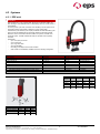

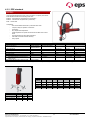
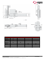
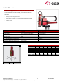
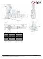
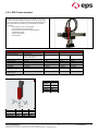
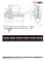
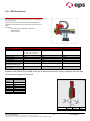
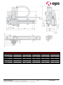


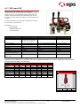
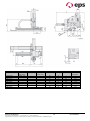
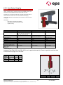

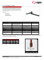
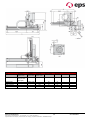
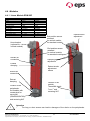
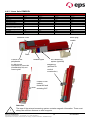
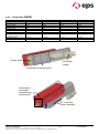

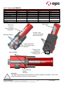
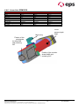
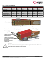
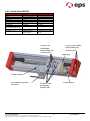
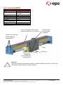
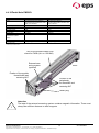
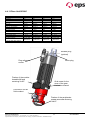
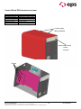
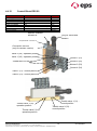
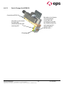
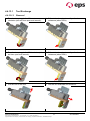
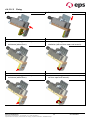

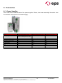

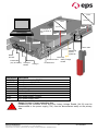

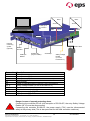


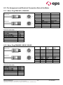
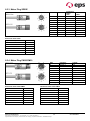
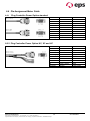
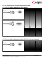
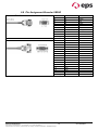
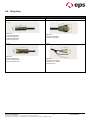

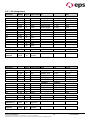
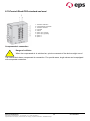

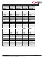
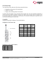


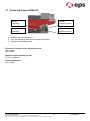
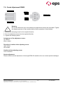


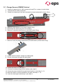

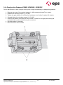


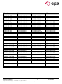


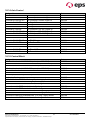


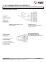


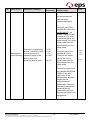


![i36l I33l EIrIIIllIrrllIl tlrxlrllIr I lrlllr]lll It DA2](http://vs1.manualzilla.com/store/data/006759536_1-e1b2d27f25e11b765edbcc7af9879218-150x150.png)