1
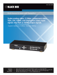
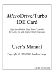
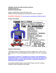
User's Manual
A
APPLIED ENGINEERING"
A DSVBKMI OF AE RESEXRCH CORPORA T K N
Applied Engineering
Telephone Numbers
Technical Support
9 AM to 12:30 PM & 1:35 to 5 PM (CST)
Monday through Friday
Do not return any
product for service without a
Return Material Authorization (RMA) number.
An RMA number can be obtained by calling Technical Support.
Sales
(214) 241-6060
9 AM to 11 PM (CST) 7 days
User's Manual
Limited Warranty & Disclaimer
Applied Engineering warrants the DClock against defects in material and workmanship for a period of 5 years from the
date of original retail purchase. Applied Engineering also warrants that, under normal use, the magnetic media on
which the included E software is stored is free from defects in materials and workmanship for a period of 30 days
from the date of original purchase. Any misuse, abuse, or non-E authorized alteration, modification andlor repair to
the Applied Engineering product will void the warranty. This warranty will also be void if you use the E product for any
other purpose than its intended use. If you discover a defect, Applied Engineering will, at its option, repair or replace
only the Applied Engineering product, provided you return the product during the warranty period, transportation
prepaid, to Applied Engineering.
This warrantv a ~ ~ l i e
t os the orlainal retail Durchaser onlv. Therefore, please include a copy of the
original invoice or a small service charge may be applied. If the product is to be sent to Applied Engineering by mail,
the purchaser will insure the package or assume full responsibility for loss or damage during shipping. Prior to
returning the product for warranty consideration, call Applied Engineering Technical Support for a Return Material
Authorization (RMA) number and shipping instructions.
Even though Applied Engineering has tested the software and reviewed the documentation, Applied Engineering
makes no warranty or representation, either express or implied, with respect to the manual or the software; their
quality, performance, merchantability, or fitness for a particular purpose. As a result, the software and manual are
sold "as is," and you, the purchaser, are assuming the entire risk as to their quality and performance.
In no event will Applied Engineering be liable for loss or damages of any kind caused either directly or indirectly by the
use or possession of its products, even if advised of the possibility of such damages. The b ~ l i e dFrlgineering
. .
Warrantv is for the Agglied Fnalneerlna Product itselt In particular, Applied Engineering shall have no liability for any
other equipment used in conjunction with Applied Engineering products nor for programs or data'stored in or used with
Applied Engineering products, including the costs of recovering such equipment, programs, or data.
The warranty and remedies set forth above are exclusive and in lieu of all others, oral or written, express or implied.
No Applied Engine'eringdealer, agent, or employee is authorized to make any modification, extension, or addition to
this warranty.
Some states do not allow the exclusion or limitation of implied warranties or liability for incidental or consequential
damages, so the above limitation or exclusion may not apply to you. This warranty gives you specific legal rights,
and you may also have other rights which may vary from state to state.
This manual and the software (computer programs) described herein are copyrighted by Applied Engineering with all
rights reserved. Under the copyright laws, this manual or the programs may not be copied, in whole or in part, without
the written consent of Applied Engineering, except in the normal use of the software or to make an archival copy.
This exception does not-allow copies to be made for others, whether or not sold, but all of the materials purchased
(with all archive copies) may be sold, loaned, or given to another person. Under the law, copying includes translating
into another language or format. You may use this software on any computer owned by you but extra copies cannot
be made for this purpose.
Applied Engineering cannot guarantee that you will receive notice of revisions to the software, documentation, or
products described in this manual. Be sure to check with your dealer or Applied Engineering for information on
possible updates. However, Applied Engineering reserves the right to make any improvements to Applied
Engineering products without any responsibility toward upgrading previously released products.
Apple is a registered trademark of Apple Computer, Inc.
Appleworks is a trademark of Apple Computer, Inc.
Applied Engineering is a registered trademark of Applied Engineering.
Ram Express, DClock, and Clockworks are trademarks of Applied Engineering.
TimeOut is a trademark of Beagle Bros, Inc.
--
-
@Copyright1988, Applied Engineering
Applied Engineering
P.O. Box 5100
Carrollton, Texas 7501 1
Sales: (214) 241-6060 9 AM - 11 PM (CST) 7 days
Technical Support: (214) 241-6069 9 AM - 12:30 & 1:35 5 PM (CST) Monday - Friday
(The Technical Support telephone lines cannot be accessed through the Sales department.)
-
Table Of Contents
-
CHAPTER ONE THEDCLOCKMODULE
What It Is
Installing DClock
CHAPTER TWO
- USING DCLOCK
Boot the Disk
"Cannot find clock" Message
Set the time
Load the Driver to Your ProDOS Boot Disks
The Clockworks Enhancements
What ClockWorks Is...
Making the Clockworks Enhancements
CHAPTER
THREE
- ABOUTTHE DCLOCKBATTERY
What it is
Replacing
APPENDICES
A: Taking Out and Putting In
Your Memory Expansion Card
Removing the Card
Putting the Card Back In
B: DClock Register Structures
C: Bird's Better 'Bye'
D: Getting Help
Returning a Product
When You Ship
When We Receive
1
1
1
5
5
5
5
6
6
6
7
9
9
9
10
10
10
12
14
17
18
19
20
20
Table of Contents
i
The DClock Module
What it is and how to install if
What It Is
DClock is the clock option for the Ram Express and Apple's IIc
Memory Expansion Card or compatibles. It's called DClock
because it fits into a DRAM socket on the expansion boards.
DClock adds a precision electronic time-keeping device to your
Apple IIc. The clock keeps track of the year, month, day of the
month, day of the week, and time, right down to 1/10 and 1/100
of a second.
An on-board lithium battery maintains the current date and
time even when the computer is turned off.
DClock will enable you to:
Support applications that can use a ProDOS time clock.
Add the current date and time to ProDOS disk files.
Display the current date and time on the AppleWorks
screen.
Enter the current date or time to AppleWorks data base
categories with just a single keystroke.
Installing DClock
It is very easy to install DClock. Before performing any one of
the steps in the installation, read through the step thoroughly
and make sure that you understand it completely.
Step 1 Remove the memory expansion card
You must first remove the memory expansion card if it is
currently installed in your IIc. Refer to your memory expansion
manual for instructions. If your manual does not have
instructions for removing the card, refer to Appendix A.
Remove the upper left stand-off
Step 2
There should be a plastic stand-off in the upper left corner of the
motherboard. If there is, remove it by pulling it up and out of
the motherboard. Needle-nosed pliers may help.
Ch. 1 - The DClock Module
1
Remove the upper left stand-off
Step 3
Remove the bottom left chip from its socket
The clock installs into the DRAM socket located at the far left
end of the bottom row of chips.
Remove chip from
1.
--
m-
Where the DClock plugs in
If you don't have a chip in that socket, go to Step 5.
If you have a chip installed in that socket, you will need to
remove it first.
Remove the chip by gently prying up the chip with the tip of a
small flatblade screwdriver. Slightly pry up one end, then the
other. The chip's legs will bend easily so rock.the chip out gently
using the flat tip of the screw to push up from beneath.
Use your thumb and forefinger to pull it completely out.
2
DClock
Step 4
Insert the memory chip into the DClock socket
If you have removed the chip described above, insert it into the
empty socket on the DClock card with the notch toward the top
(the connector end) of the card. (Refer to previous picture.)
*1.
Important! Make sure the notch is pointed toward the
top of the card. If the chip is inserted upside down, the
chip can be damaged but is usually not. However, the
memory board will not recognize the chip unless it is
installed correctly.
Plug the DClock connector into the DRAM socket
Step 5
If the protective foam block is still covering the connector pins
on the DClock card, remove it.
Q
Note: If you did not have a chip in the lower left socket
of the memory card as described in steps 3 and 4, the
socket below the connector on the DClock will remain
empty.
Insert the pins of the DClock's connector into the Ram Express'
empty socket and press in until the card is completely seated.
Insert DClock connector into socket
Install the memory card
Ram Express Owners: Go to Chapter 2 Step 7 of the Ram
Express manual.
Step 6
*>
Ch. 1 - The DClock Module
3
Follow the directions in the memory card manual for proper
installation and reassemble the IIc. (Refer to "Putting the Card
Back In" in Appendix A, for installation instructions if your
memory card does not include them.)
That's all there is to it!
Read on to find out how to access the clock and set the time.
Using DClock
ProDOS does not automatically recognize the clock. However,
the ProDOS compatible drivers on the DClock disk allow
ProDOS to recognize and use the clock information. When a
ProDOS startup disk is booted, the operating-system file,
PRODOS, is copied from the disk to a protected area of the
computer's memory. The program, DCLOCK .SYSTEM, will install
the required clock driver to the image of ProDOS in memory.
When executed, the DCLOCK. SYSTEM program will first check for
the presence of a clock and, if found, install the clock driver.
Then it will execute the next system program (file type of SYS
and a filename suffix of .SYSTEM) in the disk's directory.
Boot the Disk
Boot the DClock disk. You should see the message clock
Copyright (c) 19-- Applied Engineering in the upper left
corner of the screen. DCLOCK .SYSTEM installs the proper drivers
to the image of ProDOS in memory and then runs the BASIC
program. The BASIC program sends the message, Loading
drivers. .and brings up the Time Utilities Menu.
.
"Cannot find clock" Message
If you ever get the message cannot find clock, it probably
means that the clock has been discharged or is improperly
installed. If the clock has been discharged but is properly
installed, the program will find it and set the time and date to
zeros. Set the correct time and date as described below, then
choose the option Install clock driver in memory.
If the program does not find the clock, check the clock's
installation then try booting the DClock disk again.
Set the time
Select the option, Set the Time. Follow the on-screen
directions to set the date and time in the format:
Month (01 - 12)/Day (01 - 31)/Year (00 - 99)
Hour (00 - 23)/Minute (00 - 59)/Second (00 - 59)
9
Note: To enter PM, add 12 hours to the corresponding
AM time.
-
Ch. 2 Using DClock
5
Press Return to set the time or use the ESC key to return to the
Clock Utilities menu without changing the clock.
If you enter a value outside the range of a particular setting (ex:
Month = 13), you will receive an error message and be returned
to the main menu.
Load the Driver to Your ProDOS Boot Disks
To automatically install the proper clock driver each time the
computer is booted, install DCLOCK. SYSTEM on your ProDOS
startup disks.
9
Note: DCLOCK. SYSTEM requires 4 blocks of disk space.
To patch any ProDOS boot disks to recognize the clock, insert the
write-enabled disk to be modified into any disk drive and choose
the option I n s t a l l c l o c k d r i v e r on d i s k . The installation
program will scan the system and display a list of volumes
currently on-line and their location. Select the target volume
and press the Return key. The DCLOCK .SYSTEM file will be
inserted as the first system program in the patched disk's
directory. Each time the modified startup disk is booted,
DCLOCK SYSTEM will be executed, displaying D C l o c k C o p y r i g h t
( c ) 19-- A p p l i e d E n g i n e e r i n g in the upper left corner of
the screen; then the next system program file in the disk
directory will be executed.
.
Whenever you create or modify ProDOS files under the
modified operating system, the files will be automatically tagged
with the current date and time. Also, any application programs
which read the time and date directly from ProDOS will now be
able to do so.
The ClockWorks Enhancements
...
What Clockworks Is
Simply put, DCLOCK. SYSTEM makes DClock look like
a ProDOS
clock; ClockWorks allows AppleWorks to use the "ProDOS
clock."
4%
6
DClock
Important! The ClockWorks Time Utility is already
built into the AW 2 Expander. If you have a Ram
Express and have made the AW 2 Expander
modifications, you won't need to install the
ClockWorks driver. If you're booting your computer
with the AppleWorks disk, you'll still need to install
DCLOCK .SYSTEM as described above.
ClockWorks modifies the AppleWorks program, replacing the
message 0-?for Help in the bottom line of the AppleWorks
screen with a display of the current date and time. You can still
to access the help screen.
use 0-?
ClockWorks also allows you to enter the current date or time
into an AppleWorks Data Base category by typing the @ character
as the only entry in the category. The category name must
contain either the word DATE or TIME. If both DATE and TIME
are used in the same category, the program will default to DATE.
Set u p your categories ...
File:Scarlet
CHANGE NAME/CATEGORY
Category names
........................................
--------------
Date
Time
Time for a date
Datetime
Text
Then, while in the Insert New Records mode, enter the 8 next
to the time or date category and press Return ...
File:Scarlet
INSERT NEW RECORDS
Record 1 of 1
........................................
.....................
Date: Nov 9 88
Time: ll:17PM
Time for a date: Nov 9 88
Datetime: Nov 9 88
Text: Blah, blah, blah.
Making the Clockworks Enhancements
Use the ClockWorks Time Utility to modify only BACKUP
copies of the AppleWorks startup and program disks. Any
patches to AppleWorks required by other programs, such as the
TimeOut series, should be made after the ClockWorks utility is
installed.
Select the option Run ClockWorks from the Time Utilities
menu and follow the onscreen instructions.
Ch.2 - Using DClock
7
The program will search all the online drives for a volume
named /APPLEWORKS. If found, the program will quickly
make the modifications.
If Clockworks cannot find a volume named /APPLEWORKS,
you'll get the following message:
Unable t o f i n d f i l e .
/
Type p r e f i x of AppleWorks t o modify
If you get this message, enter the complete ProDOS prefix of the
AppleWorks STARTUP disk. The leading slash (/) is provided.
If you have copied the AppleWorks program to be modified into
a ProDOS subdirectory, enter the complete ProDOS pathname of
the subdirectory containing the AppleWorks files. Be sure to
include slashes for any subdirectories.
About the DClock Battery
What it is
The DClock's battery is a 3 volt, 12 millimeter lithium battery
with a life of about 2 years. You can order these batteries directly
from Applied Engineering or check your local computer parts
store or camera supplies store.
Replacing
To replace the battery, remove the memory expansion board and
unplug the DClock from the board. Remove the battery by
pushing on the top edge of the battery with a flatblade
screwdriver. Do not bend the clip up. The battery shou-ldpop
out the bottom of the connector.
Insert the new battery, positive (+) side up.
Now reconnect the DClock (refer to the directions in this
manual), and reinstall the memory card according to that card's
installation instructions.
Now boot the DClock disk to set the correct time.
Ch. 3 - About the DClock Battery
9
Taking Out and Puffing In Your Memory
Expansion Card
If your memory expansion card did not come with instructions
for installing and/or removing the card, carefully follow the
instructions below.
Removing the Card
Step 1 Remove the top cover of the IIc.
I) Switch the IIc power OFF.
2) Remove all cables connected to the computer.
3) Turn the computer upside-down.
4) Using the Phillips screwdriver, remove the six screws
indicated as in the picture below. Some of the earlier
model IIc's have different types of screws, shown as A
and B. As you remove these screws, mark them as to
type and keep them separated. Do not remove the four
remaining screws. They hold the disk drive in place.
Apple Ilc case screws
5)
10
Turn the computer right-side-up.
...
App. A - Taking Out and Putting In
6)
9
(IIc Plus owners, go to "7)".) Lift the left front (keyboard)
edge of the top cover about 1/2 inch and insert the
flatblade screwdriver between the top and bottom
covers, to a depth of approximately 1/4". The insertion
point for the screwdriver should be directly in line with
the "B" key on the keyboard.
While lifting on the left front edge of the top cover,
gently pry (lever) the screwdriver handle up toward the
keyboard. This will release the snap connector which
holds the front of the IIc case together.
Note: There are several snap connectors holding the IIc
case together. If some of them break off, don't worry;
the case is still good. These snaps are required only
during the original assembly of the IIc to align and hold
the case together before the screws are installed. Just
make sure that the broken plastic tabs don't rattle
around inside the computer and get into the disk drive!
(The IIc Plus does not have the same kind of
connectors,)
The next two snaps are a little tougher. These are
located on either side of the disk drive door and are
unsnapped by lifting the keyboard end of the top cover.
It may help to wiggle the top cover gently from side to
side while lifting.
7) Lift the top cover from the front rearward until it can be
unhooked from the back of the IIc.
8) Check the top cover to see that there are two metal tabs
(Tinnerman nuts) attached to the back panel. If they are
not there, find them! They can do serious damage to the
computer if left inside.
9) Set the top cover aside and proceed to the next step.
Step 2
(IIc Plus only) Remove the volume knob
The volume slide knob comes off easily. Remove it and set it
with the screws.
Flip over the keyboard
Step 3
Lift the front (spacebar) edge of the keyboard, gently moving it
away from the disk drive, exposing the ribbon cable connecting
the keyboard to the IIc main logic board. Flip the keyboard face
down over the disk drive.
App. A - Taking Out and Puiting In...
11
Step 4
Remove the card
The card should be mounted on four stand-offs directly under
where the keyboard normally rests. Remove the card from the
stand-offs by pulling up gently on the end of the card while
pushing down on the ends of the stand-offs protruding from the
back of the memory card. Release the left side of the card first
then the right end.
Step 5
Install the DClock
Now continue with Step Two of Chapter One's installation
instructions.
Putting the Card Back In
Step 1
Insert the card
Place the memory expansion card on the three stand-offs,
component (chip) side down and with the connector on the right
side. Make sure the holes in the board are aligned with-the
stand-offs then gently press down on the board starting at the
connector (right) side then at the stand-off on the left side.
You'll hear the board snap onto the stand-offs.
Step 2
Re-install the keyboard
Gently flip the keyboard back into place. Make sure that the
keyboard cable is still firmly attached to its connector.
Some IIc's will have tabs on the keyboard which fit into the disk
drive. Insert these tabs into the drive and lower the front
(spacebar) edge of the keyboard into the plastic mounting guides
on the bottom case.
Replace the volume knob (IIc Plus only)
Step 3
Return the volume slide knob to its proper position.
Replace the top cover.
Step 4
44 Note: Some of the earlier IIc top covers are made in two
pieces, a top panel and a back panel. If yours is a twopiece design, snap the two together and install them as
one piece.
1)
2)
3)
12
Verify that the Tinnerman nuts are securely attached to
the top cover.
Snap the IIc carrying handle into the notches on the rear
panel of the bottom cover.
Hook the bottom edge of the back panel (top cover)
under the power switch and back panel connectors.
App. A - Taking Out and Putting
In ...
4)
5)
6)
Lower the keyboard end forward, over the front of the
computer. Pulling the cover toward the keyboard while
lowering it. over the disk drive will make it easier to
snap the cover in place.
Holding the top and bottom covers together, turn the
computer over and replace the case screws. To prevent
binding, don't tighten the screws completely until all
screws are threaded in their holes.
Reconnect the peripheral and power cables.
App. A - Taking Out and Pufing In...
13
DClock
Sfrucfures
The DClock module uses the DS1215 clock chip. This part
coexists with the DRAM chip at Bit 0 of the third bank of
memory on the IIc memory expansion card. Normally, the clock
is transparent to the memory array. If the proper activation
sequence is written to Bit 0 of bank 3, the clock becomes active
long enough to read or set the time. The enable sequence is a
read followed by 64 writes with a bit pattern of $5CA3 3AC5 5CA3
3AC5 (LSB first). Any deviation in the sequence or an
intervening read will abort the enable. The odds of a random
data sequence duplicating this pattern during normal accesses to
the memory are less than 1 in 1019.
The clock contains eight data registers of eight bits each that
should be written or read as a block of 64 bits (LSB of register 0
first). The data is stored in BCD format. The structure of the
registers are as follows:
Register 7 Bit 6
Bit 7
Bit 5
Bit 4
Bit 3
Bit 2
Bit 1
.................................................................
I
Year 10
I
Year 1
.................................................................
-
7: Year
Bit 6
B i t 5
~ i t 0s
Register 6
(00
-
99)
Bit 4
Bit 3
Bit 2
Bit 1
.................................................................
I
0
I
0
I
0
I M 1 0 I
Month 1
.................................................................
Bits 0
Bits 5
Bit 7
-
4: Month
(Ol[Janl
-
Bit 0
I
12[Decl)
7 : N o t used
Bit 6
Bit 5
Bit 4
Bit 3
Bit 2
Bit 1
.................................................................
1
0
1
0
1
Date 10
I
Date 1
.................................................................
B i t s 0 - 5: D a t e ( 0 1 - 3 1 )
B i t s 6 - 7 : N o t used
14
I
-
Bit 7
Register 5
Bit 0
App. B - DClock Register Structures
Bit 0
.I
Register 4
-
Bit 7
Bit 6
Bit 5
Bit 4
Bit 3
Bit 2
Bit 1
.................................................................
I
0
I
0
I O s c I R s t I
0
I
Day
.................................................................
Bits 0
B i t 3:
B i t 4:
Bit
-
5:
Bits 6
-
Bit 0
I
-
2 : D a y of Week ( O l [ S u n ]
07[Sat])
Not u s e d
R e s e t b i t . A one w i l l disable e x t e r n a l resets. T h e
e x t e r n a l reset p i n i s n o t u s e d o n t h e D C l o c k .
O s c i l l a t o r b i t . A o n e w i l l stop t h e oscillator a n d h a l t
t h e c l o c k . When f i r s t p o w e r e d u p , t h i s s h o u l d be set t o
zero.
7: Not u s e d
Register 3 Bit 7
Bit 6
1 12/24 1
0
Bit 5
Bit 3
Bit 4
Bit 2
Bit 1
.................................................................
I 10/Am I H r 1 0 1
Bit 0
I
Hour 1
.................................................................
B i t s 0 - 5: H o u r ( 0 0 - 2 3 )
I f i n 1 2 H o u r m o d e , b i t s 0-4 a r e h o u r s ( 0 1 - 1 2 ) a n d
B i t 5:
t h i s b i t i s Am/Pm.
A one
i s equivalent t o Pm. Do n o t
u s e 1 2 h o u r m o d e b e c a u s e t h e driver s o f t w a r e expects 2 4
h o u r mode.
B i t 6:
N o t Used
Mode b i t . A o n e m e a n s 1 2 H o u r m o d e . U s e t h e 2 4 H o u r
B i t 7:
mode.
'
Register 2 Bit 7
Bit 6
Bit 5
Bit 3
Bit 4
Bit 2
Bit 1
.................................................................
Bit 0
1
0
1
Min 1 0
I
Min 1
.................................................................
Bits 0
B i t 7:
Register 1
-
6: M i n u t e s ( 0 0
Not Used
-
59)
-
Bit 7
Bit 6
Bit 5
Bit 3
Bit 4
Bit 2
Bit 1
.................................................................
1
0
1
Sec 10
I
Sec 1
.................................................................
Bits 0
B i t 7:
Register 0
Bit 7
I
-
6: S e c o n d s ( 0 0
Not Used
-
Bit 0
I
59)
Bit 6
Bit 5
Bit 4
Bit 3
Bit 2
Bit 1
.................................................................
I
Sec 0.1
I
Sec 0.01
.................................................................
B i t s 0 - 7: Fractional S e c o n d s (0.00 - 0.99)
Bit 0
App. B - D C l o c k R e g i s t e r Structures
I
15
On the disk supplied with the DClock are some example
assembly language routines, in both source and binary, that
access the DClock and convert BCD to binary. The routines can
be called directly or from BASIC.
16
App. B - DClock Register Structures
Bird's Better 'Bye'
The AW 2 Expander contains a modified version of ProDOS 8. It
incorporates a program selector, Bird's Better 'Bye' (created by
Alan Bird), that lets you exit one system file and easily run
another system file (e.g. APLWORKS.SYSTEM, BASIC.SYSTEM,
FILER) from a menu.
To use this 'BYE' command, boot your copy of the AW 2
Expander disk or copy the 'PRODOS' file from the AW 2
Expander disk to your boot disks. Then, anytime you quit a
system program (such as Appleworks), a menu of the first 16
executable system files and/or subdirectories on that disk will be
displayed on the screen. This menu can also be called from the
Applesoft BASIC prompt by entering the 'BYE' command.
ESC: CHANGE VOLUME
RETURN: SELECT FILE
/AWZ.EXP
PRODOS
AE.AW.SYSTEM
AECACHE-SYSTEM
GSTEST.SYSTEM
RWTEST.SYSTEM
RFTEST.SYSTEM
RETEST.SYSTEM
PCT~AM.SYSTEM
FILER
BASIC.SYSTEM
Sample screen display
The sample screen above shows the AW 2Expander disk online
and lists its executable system files.
Use the up and down arrow keys to highlight the selection you
want to run. The Esc key will change the volume (disk)
selection to the next on-line volume. The Return key selects the
currently highlighted file or subdirectory name.
Subdirectory names on the disk will be indicated by a '/' as the
first character of the file name.
App. C - Bird's Better 'Bye'
17
Getting Help
If you have a technical question relating to your DClock card or
any other Applied Engineering product that is not covered in the
manual, please contact the dealer from whom you purchased the
product. If you are experiencing difficulties with one particular
program, contact the program's author or publisher.
In the event that the dealer or the publisher's support personnel
cannot answer your question, call Applied Engineering
Technical Support. The support representatives are experienced
in the applications and uses of Applied Engineering products,
but in order to provide a quick and effective answer to your
question, they will need to know as much as possible about the
hardware and software specifically related to your question.
Please provide the technical support representative with the
following information:
0
0
0
0
0
0
The Applied Engineering product related to your
question and its revision number.
The original and current memory configuration of the
card (if applicable).
The model and revision of your computer.
What peripherals are being used.
The name, version, and revision level of the software
with which you are experiencing problems.
The results of any test programs, diagnostics, or
troubleshooting done by you, your dealer, or your
software publisher's support department.
Applied Engineering
Technical Support
(214)241-6069
9 AM to 12:30 PM & 1:35 PM to 5 PM(CST)
Monday Through Friday
(Please call only the number above for technical support. Our
sales office cannot transfer calls to the support lines.)
18
App. D - Getting Help
Returning a Product
Include
If your product needs to be returned, the technical support
representative will give you a Return Material Authorization
(RMA) number.
Record the RMA number for your own records.
Write the RMA number on the outside of the package
you send to us.
0 Write the RMA number at the top of the return form
included with your product package.
Fill out the Return Form on back of the yellow sheet marked
"Attention!" A correctly completed form will greatly reduce the
time it takes to process and return your product.
0
0
Attach a copy of your original invoice to the return forin.
e3
Warning: If you don't include an invoice, products will
be treated as out of warranty products and will be returned
to you C.O.D. for the amount of the service charge.
A completed form should look something like the one below.
0 / I . Enhalad
0 lkX ROMP
We're vslna G, Washlnoton W r l r e r and
Plnocchlo Knows.
.-
---
t h a t YOU dldn'? do In class because Y O U dldn'?
feel like I i rlqht then. Run e l i h e r ~ r o a r a r na t
rnldnlqht or a f t e r . 7 r y t o se? clock back.
Observe rnessaoe.
Appendix D - Getting Help
19
When You Ship
If you don't have the original packing material, wrap the board
in anti-static material (preferably the anti-static bag in which the
card was originally shipped; however, aluminum foil will work
fine). Pack it in a sturdy box cushioned with wadded papers (e.g.
used computer paper or newspaper).
*$.
Warning: If your product is damaged due to inadequate
packing, your warranty will be void.
Include the return form and invoice.
Send the package; shipping prepaid, to:
RMA#--?-Applied Engineering
Technical Support
3210 Belt Line Road, Suite 154
Dallas TX 75234
You should insure your package. E will not assume any
responsibility for inadequate packing or loss or damage during
shipping.
When We Receive
Our service department will use your completed form in an
attempt to duplicate the problem.
If it is determined that your product is defective due to a
manufacturing defect, your card will be repaired or replaced at
E ' s option.
Any misuse, abuse, or non-E authorized alteration,
modification, and/or repair to the Applied Engineering product
will void the warranty. This warranty will also be void if you
use the E product for any purpose other than its intended use.
Your product will be fully tested before it is shipped back to you,
transportation prepaid, via UPS regular delivery.
Once your product is received by Technical Support, it will be
processed and delivered to our shipping department within 7 to
10 working days.
23
App. D - Getting Help
,