1
HP TFT7600 G2 Rackmount Keyboard Monitor
KVM Console
User Guide
Part Number 615930-001
June 2010 (First Edition)
© Copyright 2010 Hewlett-Packard Development Company, L.P.
The information contained herein is subject to change without notice. The only warranties for HP products and services are set forth in the
express warranty statements accompanying such products and services. Nothing herein should be construed as constituting an additional
warranty. HP shall not be liable for technical or editorial errors or omissions contained herein.
ENERGY STAR and ENERGY STAR mark are registered U.S. trademarks.
Intended audience
This document is for the person who installs racks and rack products. This procedure is performed only by trained personnel. HP assumes you are
qualified in performing installations and trained in recognizing hazards in rack products.
Contents
Introduction .................................................................................................................................. 5
HP TFT7600 KVM Console features ............................................................................................................... 5
ENERGY STAR compliant .................................................................................................................... 6
Main components......................................................................................................................................... 6
Rear components ......................................................................................................................................... 7
Installation ................................................................................................................................... 8
Kit contents .................................................................................................................................................. 8
Installing the HP TFT7600 G2 Rackmount Keyboard Monitor KVM Console ....................................................... 8
Connecting and routing cables .................................................................................................................... 12
Accessing the HP TFT7600 KVM Console ..................................................................................................... 13
Removing the HP TFT7600 KVM Console ..................................................................................................... 14
Removing the HP 1U Adjustable Toolless Rails............................................................................................... 14
Removing PS2 cables with cable-locking mechanism ...................................................................................... 14
Enabling the native display resolution of 1440x900 in HP-UX ........................................................................ 15
Operational overview ................................................................................................................. 16
On-screen display ...................................................................................................................................... 16
Launching OSD menu ................................................................................................................................. 16
Navigating OSD ........................................................................................................................................ 16
OSD menu ................................................................................................................................................ 17
Brightness/Contrast .......................................................................................................................... 17
Image control .................................................................................................................................. 17
Advanced ....................................................................................................................................... 18
Auto Configuration ........................................................................................................................... 19
Factory settings ................................................................................................................................ 19
Language ........................................................................................................................................ 19
Information ...................................................................................................................................... 19
Maintenance .............................................................................................................................. 20
Maintenance guidelines .............................................................................................................................. 20
Cleaning the monitor ........................................................................................................................ 20
Shipping instructions................................................................................................................................... 21
Moving a rack with the HP TFT7600 KVM Console installed ........................................................................... 21
Specifications ............................................................................................................................. 22
HP TFT7600 KVM Console specifications ..................................................................................................... 22
Environmental requirements ............................................................................................................... 22
Regulatory compliance notices ..................................................................................................... 23
Regulatory compliance identification numbers ............................................................................................... 23
Federal Communications Commission notice ................................................................................................. 23
FCC rating label .............................................................................................................................. 23
Class A equipment ........................................................................................................................... 23
Class B equipment............................................................................................................................ 23
Declaration of conformity for products marked with the FCC logo, United States only.............................. 24
Modifications ................................................................................................................................... 24
Cables ............................................................................................................................................ 24
Canadian notice (Avis Canadien) ................................................................................................................ 24
European Union regulatory notice ................................................................................................................ 25
Japanese notice ......................................................................................................................................... 26
BSMI notice ............................................................................................................................................... 26
Korean notice ............................................................................................................................................ 26
Chinese notice ........................................................................................................................................... 27
China energy regulations ............................................................................................................................ 27
Disposal of waste equipment by users in private households in the European Union .......................................... 27
Power cord requirement .............................................................................................................................. 27
Power cord statement for Japan ................................................................................................................... 28
Electrostatic discharge ................................................................................................................. 29
Preventing electrostatic discharge ................................................................................................................ 29
Grounding methods to prevent electrostatic discharge .................................................................................... 29
Technical support ........................................................................................................................ 30
HP contact information ................................................................................................................................ 30
Acronyms and abbreviations ........................................................................................................ 31
Index ......................................................................................................................................... 32
Introduction
HP TFT7600 KVM Console features
The HP TFT7600 KVM Console is a rack-mountable 1U integrated flat-panel monitor and keyboard with
touchpad.
NOTE: 1U = 1.75 inches or 44.45 cm
The HP TFT7600 KVM Console is mounted on rails with space available to add a 1U KVM switch box
behind the unit. The console can be used with all HP racks.
The HP TFT7600 KVM Console uses a 43.9-cm (17.3-inch) color-active matrix TFT LCD ("Main
components" on page 6).
Feature
Description
Display
43.9-cm (17.3-inch) viewable area display
Resolution
640 x 480 (VGA) through 1280 x 1024 (SXGA), 1440 x 900
(WXGA+), and 1600 x 900 (WXGA+)
Monitor
input
Plugs into a standard VGA connector; does not require a special
graphics adapter card
Plug and
Play
Plug-and-Play capability if supported by your system
OSD
Available in seven languages:
•
•
•
•
•
•
•
English
French
German
Italian
Japanese
Simple Chinese
Spanish
Keyboard
with
touchpad
Three-button touchpad with scroll bar
Power supply
12v DC/36 Watt
Scroll keys
Four scroll keys (inverted T)
Introduction
5
ENERGY STAR compliant
The HP TFT7600 KVM Console is ENERGY STAR® qualified.
For more information about the ENERGY STAR® qualifications, see the HP website
(http://www.hp.com/hpinfo/globalcitizenship/environment/products/ecolabels.html).
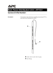
Main components
Callout
Component
Function
1
Display release latch
Pushes down to unlatch the display
assembly
2
Blue LED
•
•
Turns on when the display is closed
•
•
•
Launches OSD menus
3
OSD activation button
Helps identify the HP TFT7600 KVM
Console in a rack
Selects
Exits menus and OSD
4
OSD scroll up and
down button
Used to scroll in the OSD menu and adjust
functions
5
Scroll lock LED
Lights when Scroll lock is on
6
Cap lock LED
Lights when Cap lock is on
7
Number lock LED
Lights when Number lock is on
Introduction
6
Callout
Component
Function
8
USB connection
Pass-through to the rear USB port
9
Scroll bar
Used to scroll on the monitor
10
Right pick button
Used to select the option on the right
11
Middle pick button
Used to select the option in the middle
12
Left pick button
Used to select the option on the left
13
Touchpad
Used to move the mouse on the monitor
Rear components
Callout
Component
1
USB pass-through
2
USB keyboard and mouse port
3
PS2 keyboard port
4
PS2 mouse port
5
VGA input port
6
Power connection port
7
Serial firmware port
Introduction
7
Installation
Kit contents
Item
Quantity
HP TFT7600 KVM Console
1
M6 screws
4
6-32 screws
5
HP Adjustable Toolless Rails
2
Cable management arm, power adapter with brace rail
1
Lock plates
2
USB cables
2
PS2 cables
2
Video cable
1
Power cords
2
USB cable labels
2
This kit might contain extra hardware.
Installing the HP TFT7600 G2 Rackmount Keyboard
Monitor KVM Console
1.
Align the HP 1U Adjustable Toolless Rails with the holes marked on the rack, and snap them into
place.
a. Snap one end of the HP 1U Adjustable Toolless Rails into the retna rails.
b. Extend the other half of the HP 1U Adjustable Toolless Rails to meet the appropriate rack depth,
and snap them into place.
NOTE: If the HP 1U Adjustable Toolless Rails do not snap into place, be sure that they align
with the holes marked on the rack. The holes marked on the rack must be in the same location
for the front and rear of the rack.
Installation
8
2.
Extend the inner slides until they lock into place.
3.
Align the unit with the extended inner slides, and then insert the unit into the rack.
Installation
9
4.
From the rear of the rack, slide the brace rail assembly in between the HP 1U Adjustable Toolless
Rails.
5.
Align the screw holes on the brace rail with the screw holes on the HP 1U Adjustable Toolless Rails.
6.
Using two 6-32 screws, secure the brace rail to the HP 1U Adjustable Toolless Rails.
Installation
10
7.
Remove and discard the two shipping screws from the rear of the unit.
8.
Attach the cable management arm to the rear of the unit with two 6-32 screws.
Installation
11
9.
Connect and route the cables through the cable management arm and unit opening.
Installation is complete.
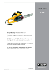
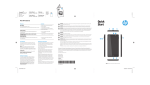
Connecting and routing cables
When connecting and routing the cables through the cable management arm and cable tray to the HP
TFT7600 KVM Console, use the following cable-routing method to ensure that the cables fit into the tray.
IMPORTANT: Use either the PS/2 cables or USB keyboard/mouse cable when connecting the
unit to a device. Do not use both.
NOTE: The PS/2 cables use the same cable-routing method as the USB keyboard/mouse
cable.
To connect and route the cables:
1.
Connect and route the power cable (1).
2.
Connect and route the VGA cable (2).
3.
Connect and route the USB keyboard/mouse cable (3).
4.
Connect and route the USB pass-through cable (4).
Installation
12
The following figure illustrates where the cables connect and how to route the cables in the tray.
Item
Description
1
Power cable
2
VGA cable
3
USB keyboard/mouse cable
4
USB pass-through cable
Accessing the HP TFT7600 KVM Console
1.
Gently extend the HP TFT7600 KVM Console until the slides lock.
2.
Push the display release latch, and then lift the display.
Installation
13
Removing the HP TFT7600 KVM Console
To remove the HP TFT7600 KVM Console, reverse the order of the steps listed in Installing the HP
TFT7600 G2 Rackmount Keyboard Monitor KVM Console (on page 8).
Removing the HP 1U Adjustable Toolless Rails
1.
Locate the spring release.
2.
Place your hand on the outside of the HP 1U Adjustable Toolless Rails so that you can move the
spring release.
3.
Gently move the spring release toward the inside of the rack (1) while moving the HP 1U Adjustable
Toolless Rails out toward you and away from the rack (2).
NOTE: If you cannot gain access to the spring release from the outside of the HP 1U
Adjustable Toolless Rails, a tool might be required to unlock the spring release from the inside
of the HP 1U Adjustable Toolless Rails.
4.
Repeat the previous steps for the other HP 1U Adjustable Toolless Rail.
Removing PS2 cables with cable-locking mechanism
PS2 cables have a locking mechanism to provide a secure cable connection. You must use proper
procedures when disconnecting these cables.
CAUTION: Failure to follow proper disconnect procedures could result in damage to the
cable or to your unit.
To properly disconnect a PS2 cable:
1.
Grasp the housing.
Installation
14
2.
Slide it back to release the locking mechanism and gently pull to remove the cable.
Enabling the native display resolution of 1440x900
in HP-UX
To fix issues related to wide screen panels, verify that you have at least one of the following server
patches (or newer) installed:
•
PHSS_40809 (11.31)
•
PHSS_40810 (11.23)
For more information about setting resolutions in HP-UX, see the Graphics Administration Guide for HP-UX
11.x servers on the HP website (http://www.docs.hp.com/en/5900-0585/5900-0585.pdf).
Installation
15
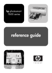
Operational overview
On-screen display
The OSD buttons are used to operate the HP TFT7600 KVM Console OSD menus.
Callout
Component
Function
1
OSD activation button
•
•
•
2
OSD scroll up and down button
Launches OSD menus
Selects menu options
Exits menus and OSD
Used to scroll in the OSD menu
and adjust the function
Launching OSD menu
To launch the OSD menu:
1.
Press the OSD activation button on the front panel. The main menu displays on the screen.
2.
To select a menu item, scroll up or down by pressing OSD scroll up and down button.
3.
Press the OSD activation button again to select your choice. A second level will expand menu items.
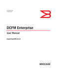
Navigating OSD
To navigate through the OSD menus and functions:
•
Use the Up (+) or Down (-) button to scroll through the OSD menu or an OSD sub-menu. The Up (+)
and Down (-) button are also used to adjust or change a function setting.
Operational overview 16
•
Use the OSD activation button to select a sub-menu or a function.
Example:
To exit the OSD menu:
1.
Press the Down (-) button to scroll to the Exit function.
2.
Press the OSD activation button to select the Exit function and exit the OSD menu.
OSD menu
The OSD menu provides access to display settings and functions, enabling the user to customize the HP
TFT7600 KVM Console display settings.
Brightness/Contrast
The Brightness/Contrast option contains the following options:
•
Brightness
•
Contrast
•
Exit sub-menu
Brightness
The Brightness option displays a slider bar to enable the adjustment of the back light brightness.
Contrast
The Contrast option displays a slider bar to enable the adjustment of the screen contrast. Contrast
adjustments are more discernable when the background is white.
Image control
The Image control option contains the following sub-menu:
•
Horizontal position
•
Vertical position
•
Clock
•
Phase
•
Exit sub-menu
Horizontal position
The H position option displays a slider bar to enable the adjustment of the screen's horizontal position.
The center of the bar is obtained from the factory-preset value for Horizontal Position. At value=MIN, the
selection of + positioning response might vary between XGA and SXGA panels. This is caused by
physical limitations at MIN OSD placement.
Operational overview 17
Vertical position
The V position option displays a slider bar to enable the adjustment of the screen's vertical position.
The center of the bar is obtained from the factory-preset value for Vertical Position.
Clock
The Clock option displays a slider bar to enable the adjustment of the Horizontal Clocks.
Phase
The Phase option displays a slider bar to enable the adjustment of the analog signals phase.
Advanced
The Advanced option provides access to the following options:
•
OSD settings menu
•
Exit sub-menu
OSD settings
The OSD settings option provides access to the following options:
•
Lock OSD settings
o
Yes
o
No
•
Timeout
•
V position
•
H position
•
Exit sub-menu
Lock OSD settings
The Lock OSD settings option locks or unlocks the OSD settings.
Timeout
The Timeout option displays a slider bar at the right side of the OSD display to enable the adjustment of
OSD timeout. The timeout ranges from 5 to 60 seconds with 1-second intervals. The default setting is 10
seconds.
Vertical position
The V position option enables the location of the OSD window to move up or down on the screen.
Horizontal position
The H position option enables the location of the OSD window to move left or right on the screen.
Operational overview 18
Auto Configuration
The Auto Configuration option performs four functions automatically:
•
Auto Level—Automatically adjusts the black and white levels of the screen
•
Auto Position—Automatically adjusts the position of the screen
•
Auto Phase—Automatically adjusts the phase
•
Auto Clock—Automatically adjusts the output clock per line to match the input
Factory settings
The Factory settings option enables the user to set the HP TFT7600 back to its original factory settings. The
following options are available in the Factory settings menu list:
•
Yes
•
No
•
Exit sub-menu
Language
The Language option allows the user to change the language in which the menu options are displayed.
The following languages are available:
•
English
•
French
•
German
•
Italian
•
Japanese
•
Simple Chinese
•
Spanish
Information
The Information option provides the following unit information:
•
Current mode
•
Recommended mode
•
SW version
•
Exit sub-menu
Operational overview 19
Maintenance
Maintenance guidelines
To protect your unit from overheating and other types of damage:
•
Use only a power source and connection appropriate for this unit, as indicated on the marking label
and back plate.
•
If an extension cord or power strip is used, be sure that the cord or strip is rated for the product.
Also, be sure that the total ampere ratings of all products plugged into the extension cord or power
strip do not exceed 80% of the extension cord or power strip ampere ratings limit.
•
Do not overload an electrical outlet, power strip, or convenience receptacle. The overall system load
must not exceed 80% of the branch circuit rating. If power strips are used, do not allow the load to
exceed 80% of the power strip input rating.
•
Install the unit near an outlet that you can reach easily. Disconnect the unit by grasping the plug
firmly and pulling it from the outlet. Do not disconnect the plug by pulling the cord.
•
Disconnect the unit from the wall before cleaning. Do not use liquid or aerosol cleaners.
•
Slots and openings in the monitor are provided for ventilation. These openings must not be blocked
or covered. Do not push objects of any kind into these slots or openings.
•
Do not drop the unit or place it on an unstable surface.
•
Do not allow anything to rest on the power cord. Do not step on the cord.
•
Keep the unit in a well-ventilated area, away from excessive light, heat, and moisture. Keep the
monitor away from high-capacity transformers, electric motors, and other strong magnetic fields.
•
Do not attempt to service this product yourself. Adjust only those controls that are covered by the
operating instructions. If the unit is not operating properly or has been dropped or damaged, contact
your HP authorized dealer, reseller, or service provider.
Cleaning the monitor
To clean the display:
1.
Turn off and unplug the unit.
2.
Dust the panel by wiping the screen with a soft, clean cloth.
If the screen requires additional cleaning, use any anti-static LCD screen cleaner.
CAUTION: Do not use benzene, thinner, ammonia, or any volatile substance to clean the
monitor screen or cabinet. These chemicals might damage the monitor. Never use water to
clean an LCD screen.
Maintenance
20
Shipping instructions
Keep the original packing box in a storage area in case you must move or ship your HP TFT7600 KVM
Console.
Moving a rack with the HP TFT7600 KVM Console
installed
When moving the HP TFT7600 KVM Console installed in a rack, HP recommends that you install the lock
plates, included in your kit, on each side of the unit and rack.
To install lock plates:
1.
Place the lock plate into the slot and rotate it back.
2.
Insert one M6 screw into the hole on the lock plate, securing the unit to the rack.
3.
Repeat steps 1 and 2 to install the other lock plate.
Maintenance
21
Specifications
HP TFT7600 KVM Console specifications
Item
Specifications
Display size
43.9 cm (17.3 inch)
Display type
Flat panel, active matrix-TFT LCD
Viewable image size
43.9 cm (17.3 inch) diagonal
Maximum weight
(unpacked)
4.5 kg (10 lb)
Maximum height
4.2 cm (1.7 inch)
Maximum depth
42.3 cm (16.7 inch)
Maximum width
43.2 cm (16.9 inch)
Resolution
1440 x 900 (WXGA+) (recommended for maximum performance) 640 x 480
(VGA) through 1280 x 1024 (SXGA)
Response time
<16 ms
Brightness
>187 (cd/m^2)
Contrast ratio
>500:1
Environmental requirements
Item
Specifications
Operating temperature
0º to 40º C (32º to 104º F)
Storage temperature
-20º to 60º C (68º to 140º F)
Humidity (Non-condensing)
Operating
10% to 90%
Non-operating
10% to 90%
Power source
Input rating
90 to 264 VAC, 47 to 63 Hz
Power consumption
<36 Watts
Specifications
22
Regulatory compliance notices
Regulatory compliance identification numbers
For the purpose of regulatory compliance certifications and identification, this product has been assigned
a unique regulatory model number. The regulatory model number can be found on the product nameplate
label, along with all required approval markings and information. When requesting compliance
information for this product, always refer to this regulatory model number. The regulatory model number is
not the marketing name or model number of the product.
Federal Communications Commission notice
Part 15 of the Federal Communications Commission (FCC) Rules and Regulations has established Radio
Frequency (RF) emission limits to provide an interference-free radio frequency spectrum. Many electronic
devices, including computers, generate RF energy incidental to their intended function and are, therefore,
covered by these rules. These rules place computers and related peripheral devices into two classes, A
and B, depending upon their intended installation. Class A devices are those that may reasonably be
expected to be installed in a business or commercial environment. Class B devices are those that may
reasonably be expected to be installed in a residential environment (for example, personal computers).
The FCC requires devices in both classes to bear a label indicating the interference potential of the device
as well as additional operating instructions for the user.
FCC rating label
The FCC rating label on the device shows the classification (A or B) of the equipment. Class B devices
have an FCC logo or ID on the label. Class A devices do not have an FCC logo or ID on the label. After
you determine the class of the device, refer to the corresponding statement.
Class A equipment
This equipment has been tested and found to comply with the limits for a Class A digital device, pursuant
to Part 15 of the FCC Rules. These limits are designed to provide reasonable protection against harmful
interference when the equipment is operated in a commercial environment. This equipment generates,
uses, and can radiate radio frequency energy and, if not installed and used in accordance with the
instructions, may cause harmful interference to radio communications. Operation of this equipment in a
residential area is likely to cause harmful interference, in which case the user will be required to correct
the interference at personal expense.
Class B equipment
This equipment has been tested and found to comply with the limits for a Class B digital device, pursuant
to Part 15 of the FCC Rules. These limits are designed to provide reasonable protection against harmful
interference in a residential installation. This equipment generates, uses, and can radiate radio frequency
energy and, if not installed and used in accordance with the instructions, may cause harmful interference
Regulatory compliance notices 23
to radio communications. However, there is no guarantee that interference will not occur in a particular
installation. If this equipment does cause harmful interference to radio or television reception, which can
be determined by turning the equipment off and on, the user is encouraged to try to correct the
interference by one or more of the following measures:
•
Reorient or relocate the receiving antenna.
•
Increase the separation between the equipment and receiver.
•
Connect the equipment into an outlet on a circuit that is different from that to which the receiver is
connected.
•
Consult the dealer or an experienced radio or television technician for help.
Declaration of conformity for products marked with the FCC
logo, United States only
This device complies with Part 15 of the FCC Rules. Operation is subject to the following two conditions:
(1) this device may not cause harmful interference, and (2) this device must accept any interference
received, including interference that may cause undesired operation.
For questions regarding this product, contact us by mail or telephone:
•
Hewlett-Packard Company
P. O. Box 692000, Mail Stop 530113
Houston, Texas 77269-2000
•
1-800-HP-INVENT (1-800-474-6836). (For continuous quality improvement, calls may be recorded
or monitored.)
For questions regarding this FCC declaration, contact us by mail or telephone:
•
Hewlett-Packard Company
P. O. Box 692000, Mail Stop 510101
Houston, Texas 77269-2000
•
1281-514-3333
To identify this product, refer to the part, series, or model number found on the product.
Modifications
The FCC requires the user to be notified that any changes or modifications made to this device that are
not expressly approved by Hewlett-Packard Company may void the user’s authority to operate the
equipment.
Cables
Connections to this device must be made with shielded cables with metallic RFI/EMI connector hoods in
order to maintain compliance with FCC Rules and Regulations.
Canadian notice (Avis Canadien)
Class A equipment
Regulatory compliance notices 24
This Class A digital apparatus meets all requirements of the Canadian Interference-Causing Equipment
Regulations.
Cet appareil numérique de la classe A respecte toutes les exigences du Règlement sur le matériel
brouilleur du Canada.
Class B equipment
This Class B digital apparatus meets all requirements of the Canadian Interference-Causing Equipment
Regulations.
Cet appareil numérique de la classe B respecte toutes les exigences du Règlement sur le matériel
brouilleur du Canada.
European Union regulatory notice
Products bearing the CE marking comply with the following EU Directives:
•
Low Voltage Directive 2006/95/EC
•
EMC Directive 2004/108/EC
•
Ecodesign Directive 2009/125/EC, where applicable
CE compliance of this product is valid if powered with the correct CE-marked AC adapter provided by
HP.
Compliance with these directives implies conformity to applicable harmonized European standards
(European Norms) that are listed in the EU Declaration of Conformity issued by HP for this product or
product family and available (in English only) either within the product documentation or at the following
HP website (http://www.hp.eu/certificates) (type the product number in the search field).
The compliance is indicated by one of the following conformity markings placed on the product:
For non-telecommunications products and for EU harmonized telecommunications products, such as
Bluetooth® within power class below 10mW.
For EU non-harmonized telecommunications products (If applicable, a 4-digit notified body number is
inserted between CE and !).
Please refer to the regulatory label provided on the product.
The point of contact for regulatory matters is Hewlett-Packard GmbH, Dept./MS: HQ-TRE, Herrenberger
Strasse 140, 71034 Boeblingen, GERMANY.
Regulatory compliance notices 25
Japanese notice
BSMI notice
Korean notice
Class A equipment
Class B equipment
Regulatory compliance notices 26
Chinese notice
Class A equipment
China energy regulations
Disposal of waste equipment by users in private
households in the European Union
This symbol on the product or on its packaging indicates that this product must not be
disposed of with your other household waste. Instead, it is your responsibility to dispose of
your waste equipment by handing it over to a designated collection point for the recycling of
waste electrical and electronic equipment. The separate collection and recycling of your
waste equipment at the time of disposal will help to conserve natural resources and ensure
that it is recycled in a manner that protects human health and the environment. For more
information about where you can drop off your waste equipment for recycling, please contact
your local city office, your household waste disposal service or the shop where you
purchased the product.
Power cord requirement
The power cord should be approved for use in your country. The power cord must be rated for the
product and for the voltage and current marked on the electrical ratings label of the product. The voltage
and current rating for the cord should be greater than the voltage and current rating marked on the
Regulatory compliance notices 27
product. In addition, the diameter of the wire must be a minimum of 1.00 mm2 or 18 AWG, your
maximum length may be up to 3.66 m (12 ft).
Power cord statement for Japan
Regulatory compliance notices 28
Electrostatic discharge
Preventing electrostatic discharge
To prevent damaging the system, be aware of the precautions you need to follow when setting up the
system or handling parts. A discharge of static electricity from a finger or other conductor may damage
system boards or other static-sensitive devices. This type of damage may reduce the life expectancy of the
device.
To prevent electrostatic damage:
•
Avoid hand contact by transporting and storing products in static-safe containers.
•
Keep electrostatic-sensitive parts in their containers until they arrive at static-free workstations.
•
Place parts on a grounded surface before removing them from their containers.
•
Avoid touching pins, leads, or circuitry.
•
Always be properly grounded when touching a static-sensitive component or assembly.
Grounding methods to prevent electrostatic
discharge
Several methods are used for grounding. Use one or more of the following methods when handling or
installing electrostatic-sensitive parts:
•
Use a wrist strap connected by a ground cord to a grounded workstation or computer chassis. Wrist
straps are flexible straps with a minimum of 1 megohm ±10 percent resistance in the ground cords.
To provide proper ground, wear the strap snug against the skin.
•
Use heel straps, toe straps, or boot straps at standing workstations. Wear the straps on both feet
when standing on conductive floors or dissipating floor mats.
•
Use conductive field service tools.
•
Use a portable field service kit with a folding static-dissipating work mat.
If you do not have any of the suggested equipment for proper grounding, have an authorized reseller
install the part.
For more information on static electricity or assistance with product installation, contact an authorized
reseller.
Electrostatic discharge
29
Technical support
HP contact information
For the name of the nearest HP authorized reseller:
•
See the Contact HP worldwide (in English) webpage
(http://welcome.hp.com/country/us/en/wwcontact.html).
For HP technical support:
•
•
In the United States, for contact options see the Contact HP United States webpage
(http://welcome.hp.com/country/us/en/contact_us.html). To contact HP by phone:
o
Call 1-800-HP-INVENT (1-800-474-6836). This service is available 24 hours a day, 7 days a
week. For continuous quality improvement, calls may be recorded or monitored.
o
If you have purchased a Care Pack (service upgrade), call 1-800-633-3600. For more
information about Care Packs, refer to the HP website (http://www.hp.com/hps).
In other locations, see the Contact HP worldwide (in English) webpage
(http://welcome.hp.com/country/us/en/wwcontact.html).
Technical support
30
Acronyms and abbreviations
KVM
keyboard, video, and mouse
LCD
liquid crystal display
LED
light-emitting diode
OSD
on-screen display
RKM
rackmount keyboard monitor
TFT
thin film transistor
USB
universal serial bus
VGA
video graphics array
Acronyms and abbreviations
31
Index
A
I
accessing the unit 13
Advanced 18
authorized reseller 30
auto-configuration process 19
Image Enhancement 17
installation instructions 8
installation overview 8
introduction 5
B
J
BSMI notice 26
Japanese notice 26
C
K
cable connectors 14
cables, connecting and routing 12
Canadian notice 24
Clock Adjust 18
components 6, 7, 29
kit contents 8
Korean notices 26
D
Declaration of Conformity 24
default 18
E
electrostatic discharge 29
Energy Star 6
environmental specifications 22
European Union regulatory notice 25
F
factory default settings 19
FCC rating label 23
features 5
Federal Communications Commission (FCC)
notice 23, 24
G
L
languages 19
M
maintenance 20
maintenance guidelines 20
moving a rack with the unit installed 21
N
native resolution 15
notices 2
O
On-screen display 16
operational overview 14, 16
OSD lockout 18
OSD menu 17
OSD position 18
OSD settings 18
OSD, launching 16
grounding methods 29
P
H
Phase adjust 17, 18
power cord 27, 28
PS/2 devices 14
Horizontal Position 17
HP website 30
Index 32
R
rear components 7
regulatory compliance notices 23, 27
Removing the Brace Rail Assembly 14
removing the HP 1U Adjustable Toolless Rails 14
removing the unit 14
S
shipping the unit 21
specifications 22, 27
T
technical support 30
telephone numbers 30
V
Vertical Position 18
W
website, HP 30
Index 33