1
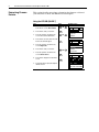
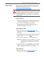
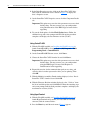
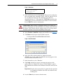
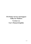
Release Notes
PowerFlex 70 Drive with Enhanced Control
Option Firmware 5.001
This release note describes major revision 5, minor revision 1 of firmware
for the PowerFlex 70 drive with Enhanced Control option only. Refer to
publication 20A-RN001 thru 20A-RN003 for a complete description of the
changes implemented in previous firmware revisions.
P096 [TB Man Ref Sel]
Additional options (18…20) have been added to [TB Man Ref Sel],
parameter 096 allowing the HIM to supply a manual speed reference when a
digital input is configured for “Auto/Manual.”
096 [TB Man Ref Sel]
Default:
Sets the manual speed reference source Options:
when a digital input (parameter
361…366) is configured for “Auto/
Manual.”
(1)
Speed References
(2)
SPEED COMMAND
New Features/
Enhancements
1
“Analog In 1”
1
2
3-8
9
10-17
18
19
20
“Analog In 1”
“Analog In 2” (1)
“Reserved”
“MOP Level”
“Reserved”
“DPI Port 1” (2)
“DPI Port 2” (2)
“DPI Port 3” (2)
“Analog In 2” is not a valid selection if it
was selected for any of the following:
- P117 [Trim In Select]
- P128 [PI Feedback Sel]
- P126 [PI Reference Sel]
- P147 [Current Lmt Sel]
- P179 [Sleep Wake Ref]
Requires a Series B HIM with firmware v5.004.01 or greater.
Selects the HIM to provide the manual speed reference when a digital input is
configured for “Auto/Manual.”
Additionally, if [Man Ref Preload], parameter 193 is set to “Enabled,” the automatic
speed reference will be preloaded into the HIM when the drive switches to Manual
mode from Automatic mode.
• Set [Save HIM Ref], parameter 192, bit 1 (Manual Mode) as desired.
• Set [TB Man Ref Sel] to the desired drive reference when in Manual Mode. If set
to one of the DPI Ports, then [Man Ref Preload] must be set to enable or disable
reference preload of the current speed. Connect a HIM to the DPI Port selected.
• When Manual mode is requested through the terminal block digital input, the
drive evaluates if Manual mode can be granted.
• If [TB Man Ref Sel] is set to a DPI Port and [Man Ref Preload] is enabled, the
drive transfers the last value of the automatic speed reference to the HIM. The
HIM is now the speed reference source. The terminal block has exclusive control
based on [Save HIM Ref], bit 1 (Manual Mode). If [Man Ref Preload] is disabled,
the HIM is now the speed reference source. The terminal block has exclusive
control based on [Save HIM Ref], bit 1 (Manual Mode).
Important: the HIM does not enter Manual mode, it is only the reference source for
the terminal block.
When Auto mode is requested through the terminal block, the drive changes to
Auto mode and returns control and reference to the previous state before Manual
mode was requested.
097
098
PowerFlex 70 Drive with Enhanced Control Option Firmware 5.001
[Digital Inx Sel], parameters 361…366
An additional option, “Manual/Auto” (68) has been added.
361
362
363
364
365
366
[Digital In1 Sel]
[Digital In2 Sel]
[Digital In3 Sel]
[Digital In4 Sel]
[Digital In5 Sel]
[Digital In6 Sel] (7)
Selects the function for the digital inputs.
(1)
When [Digital Inx Sel] is set to option 2
“Clear Faults” the Stop button cannot
be used to clear a fault condition.
(2)
3
0
0
0
0
1
1
1
1
2
0
0
1
1
0
0
1
1
1
0
1
0
1
0
1
0
1
<– “Speed Sel 1-3”
Reference A - P90
Reference B - P93
Preset Speed 2 - P102
Preset Speed 3 - P103
Preset Speed 4 - P104
Preset Speed 5 - P105
Preset Speed 6 - P106
Preset Speed 7 - P107
To access Preset Speed 1, set [Speed
Ref A Sel] or [Speed Ref B Sel] to
“Preset Speed 1”.
Digital Inputs
INPUTS & OUTPUTS (File J)
(3)
3
0
0
0
0
1
1
1
1
2
0
0
1
1
0
0
1
1
1
0
1
0
1
0
1
0
1
<– “Spd/Trq Sel1-3”
Zero Torque
Spd Reg
Torque Reg
Min Spd/Trq
Max Spd/Trq
Sum Spd/Trq
Absolute
Zero Trq
(4) Enhanced Control Drives Only.
(5) Enhanced Firmware V2.001 and later.
(6)
(7)
(8)
Opening an “Enable” input will cause the
motor to coast-to-stop, ignoring any
programmed Stop modes.
A dedicated hardware enable input is
available via a jumper selection. Refer to
page 1-19 for further information.
Configures the input to command a
transition between the Manual/Auto or
Auto/Manual speed references. Refer to
pages 1-22 and 1-23 for details.
“Manual/Auto” (68) is similar to “Auto/
Manual” (18) except that the polarity is
opposite.
Input
State
Lo
Hi
(9)
“Auto/Manual”
(18)
Auto
Manual
“Manual/Auto”
(68)
Manual
Auto
Default:
Default:
Default:
Default:
Default:
Default:
Options:
4
5
18
15
16
17
0
1
2
3
4
5
6
7
8
9
10
11
12
13
14
15-17
18
19
20
21
22
23
24
25
26
27
28
29
30
31-33
34
35
36-40
41-42
43
44
45
46
47-57
58
59
68
“Stop – CF”(1)
“Start”
“Auto/ Manual”
“Speed Sel 1”
“Speed Sel 2”
“Speed Sel 3”
“Not Used”
“Enable”(6)
“Clear Faults”(1)
“Aux Fault”
“Stop – CF”(1)
“Start”(9)(11)
“Fwd/ Reverse”(9)
“Run”(10)
“Run Forward”(10)
“Run Reverse”(10)
“Jog”(9) “Jog1”(4)
“Jog Forward”
“Jog Reverse”
“Stop Mode B”
“Bus Reg Md B”
“Speed Sel 1-3”(2)
“Auto/ Manual”(8)
“Local”
“Acc2 & Dec2”
“Accel 2”
“Decel 2”
“MOP Inc”(12)
“MOP Dec”(12)
“Excl Link”(12)
“PI Enable”
“PI Hold”
“PI Reset”
“Reserved”
“Precharge En”(4)(12)
“Spd/Trq Sel1-3”(3)(13)
“Jog 2”(4)
“PI Invert”(4)
“Reserved”
“UserSet Sel1-2” (5)
“Run Level” (5)(12)
“RunFwd Level” (5)(12)
“RunRev Level” (5)(12)
“Run w/Comm” (5)(12)
“Reserved”
“Sync Enable”(13)
“Traverse Ena”(13)
“Manual/Auto”(8)
Typical 3-Wire Inputs - Requires that
only 3-wire functions are chosen.
Including 2-wire selections will cause a
type 2 alarm.
(10) Typical 2-Wire Inputs - Requires that
only 2-wire functions are chosen.
Including 3-wire selections will cause a
type 2 alarm.
(11) A “Dig In ConflictB” alarm will occur if a “Start” input is programmed without a
“Stop” input. Type 2 Alarms - Some digital input programming may cause conflicts
that will result in a Type 2 alarm. Example: [Digital In1 Sel] set to 5 “Start” in 3-wire
control and [Digital In2 Sel] set to 7 “Run” in 2-wire. Refer to Alarm Descriptions on
page 4-8 for information on resolving this type of conflict.
(12) Refer to Option Definitions on page 3-62.
(13) Enhanced Firmware V3.002 and later.
100
156
162
096
140
194
380
125
088
108
124
205
620
2
PowerFlex 70 Drive with Enhanced Control Option Firmware 5.001
3
P175 [Auto Restart Delay]
Default:
175 [Auto Rstrt Delay]
Restart Modes
DYNAMIC CONTROL (File D)
Increased [Auto Restart Delay], parameter 175 maximum time to
6000.0 seconds.
Sets the time between restart attempts
when [Auto Rstrt Tries] is set to a value
other than zero.
1.0 Secs
174
Min/Max: 0.5/6000.0 Secs
Units:
0.1 Secs
The HIM display shows AutoRst X,YY during the restart delay. Where X is
the number of restarts left and YY is the time left before restart. For delay
times of 99 seconds or less, YY displays the seconds remaining before
restart. For delay times greater than 99 seconds, YY changes to the percent
of delay time remaining before restart.
Description
Restarts Remaining = 8
Delay Time = 93 seconds
Example Screen
F-> AutoRst 8,93
Auto
F
2
Auxiliar y Input
Time Sinc e Fau lt
00000:00:31
Corrected Anomalies
Function
Start-up
[Wake Time], parameter 181
[Sleep Time], parameter 183
Precharge Delay Time
Bus Regulation
[Dig Out1 Level], parameter 381
[Dig Out2 Level], parameter 385
This section describes the anomalies corrected in this revision.
Anomaly
When performing the following Start Up procedure – Detailed
> Start/Stop/IO > Analog Outputs > Analog Out 1 > Analog
Out 1 Sel > Signal Type – The drive may lock up, requiring a
power cycle to use the drive.
[Wake Time] and [Sleep Time] maximum value is 131
seconds.
Precharge delay time was changed to 100 milliseconds in
v4.001.
The drive may trip on Bus Overvoltage without the bus
regulator engaging. The bus regulator engagement level is
based on bus memory, with no maximum limit. This can cause
the Bus Memory level to exceed the Bus Overvoltage level.
Digital Out Level incorrect for At PI Error - when At PI Error
was set at 10.0 the output was turning on at 1.0%.
Correction
Corrected in v5.001
Expanded maximum value to 1000.0 seconds.
To prevent reduced life of the precharge relay, the
time was increased to 300 milliseconds.
To prevent nuisance braking and bus overvoltage
faults, the Bus Memory will have a defined
maximum value based on drive rating.
Corrected decimal point error in code.
4
PowerFlex 70 Drive with Enhanced Control Option Firmware 5.001
Determining Firmware
Revision
This section describes procedures to determine the firmware revision of
your PowerFlex 70 drive with Enhanced Control option.
Using the LCD HIM (20-HIM-**)
Step
1. In the main menu, press the Up Arrow or
Down Arrow to scroll to Device Select.
Key(s)
Example Screens
OR
2. Press Enter to enter your selection.
3. Press the Up Arrow or Down Arrow to
scroll to the PowerFlex 70 EC drive.
OR
4. Press Enter to select the drive. The main
menu for the drive will appear.
5. Press the Up Arrow or Down Arrow to
scroll to Diagnostics.
6. Press Enter to enter your selection.
7. Press the Up Arrow or Down Arrow to
scroll to Device Version.
8. Press Enter to display the Product Data
screen.
9. Press Enter again to display the adapter’s
firmware version.
OR
F-> Stopped
Auto
0.00
Hz
Main Menu:
Diagnostics
Parameter
Device Select
F-> Stopped
Auto
0.00
Hz
Main Menu:
Diagnostics
Parameter
Device Select
F-> Stopped
Auto
Pt0: PowerFlex 70 EC
Next
Prev
PowerFlex 70 EC
240V 4.2A
FW: 4.001
HW: A Date: 04/17/2009
PowerFlex 70 Drive with Enhanced Control Option Firmware 5.001
5
Using DriveExplorer Lite/Full
1. Launch DriveExplorer and go online (via 1203-USB or 1203-SSS
converter) with the connected drive.
2. In the DriveExplorer treeview, click on the PowerFlex 70 EC drive as
shown in Figure 1.
3. Click the information icon to display the drive’s Properties screen.
4. The “Revision:” field shows the present revision (for example, 3.003) of
the drive firmware.
TIP: When clicking on the drive using version 5.01 or higher
DriveExplorer Lite/Full, the drive firmware revision is also shown in the
right pane of the DriveExplorer window.
Figure 1 Information Icon in DriveExplorer Window
Step 3
Step 2
Step 4
6
PowerFlex 70 Drive with Enhanced Control Option Firmware 5.001
Using DriveExecutive
1. Launch DriveExecutive and go online with the connected drive.
2. In the DriveExecutive treeview, click on the PowerFlex 70 EC drive as
shown in Figure 2.
3. Click the information icon to display the drive’s Properties screen.
4. The “Revision:” field shows the present revision (for example, 3.003) of
the drive firmware.
Figure 2 Information Icon in DriveExecutive Window
Step 3
Step 2
Step 4
PowerFlex 70 Drive with Enhanced Control Option Firmware 5.001
Firmware Flashing
7
This section describes procedures to flash upgrade your drive firmware.
Flash kits for drives and communications adapters are provided on the
Allen-Bradley Web Updates site located at:
http://www.ab.com/support/abdrives/webupdate
!
ATTENTION: Risk of permanent equipment damage exists. Once a flash
update has been started, do not remove power from the drive until after the
download has completed and the STS status indicator on the drive becomes
FLASHING GREEN. If power is removed before this occurs, the drive
may be permanently damaged. A drive that has been damaged in this way
cannot be repaired.
Installing the Flash Kit
1. Install the flash kit utility from the Allen-Bradley Web Updates site for
the PowerFlex 70 EC drive. (This also automatically installs the latest
version of the ControlFLASH utility on your computer.)
2. You are now ready to use DriveExplorer, DriveExecutive,
ControlFLASH or HyperTerminal to update the drive. Follow the
instructions in the appropriate section below.
Using DriveExplorer Lite/Full
1. With the Flash Kit installed (see Installing the Flash Kit), launch
DriveExplorer and go online (via a 1203-USB or 1203-SSS converter)
with the drive.
2. In the DriveExplorer treeview, click on the PowerFlex 70 EC drive. Then
click the information icon as shown in Figure 1 to display the drive’s
Properties screen.
3. On the PowerFlex 70 EC Properties screen, click the Details tab.
Important: This update may cause the drive parameters to revert to their
default values. You may want to save your configuration
using DriveExplorer or the HIM CopyCat feature before
upgrading.
4. To start the flash update, click the Flash Update… button. Follow the
additional steps and screen prompts until the flash update procedure
completes and displays the new firmware revision (v5.001).
Using DriveExecutive
1. With the Flash Kit installed (see Installing the Flash Kit), launch
DriveExecutive and go online with the connected drive.
8
PowerFlex 70 Drive with Enhanced Control Option Firmware 5.001
2. In the DriveExecutive treeview, click on the PowerFlex 70 EC drive.
Then click the information icon as shown in Figure 2 to display the
drive’s Properties screen.
3. On the PowerFlex 70 EC Properties screen, click the Component Details
tab.
Important: This update may cause the drive parameters to revert to their
default values. You may want to save your configuration
using DriveExecutive or the HIM CopyCat feature before
upgrading.
4. To start the flash update, click the Flash Update button. Follow the
additional steps and screen prompts until the flash update procedure
completes and displays the new firmware revision (v5.001).
Using ControlFLASH
1. With the Flash Kit installed (see Installing the Flash Kit on page 6),
launch ControlFLASH by selecting Start > (All) Programs > Flash
Programming Tools > ControlFLASH.
2. On the ControlFLASH Welcome screen, click Next >.
3. Choose the PowerFlex 70 EC from the list and click Next >.
Important: This update may cause the drive parameters to revert to their
default values. You may want to save your configuration
using the HIM CopyCat feature, DriveExplorer or
DriveExecutive before upgrading.
4. Expand the treeview for the communication path you are using, and
select the drive icon that represents the drive you are updating. Then
click OK.
5. With the Multiple Assemblies Found window displayed, select “Port 0 PowerFlex 70 EC” from the list and click OK.
6. With the Firmware Revision window displayed, select “5.001.xx” from
the list of available updates and click Next >. Follow the remaining steps
and screen prompts until the flash procedure completes and displays the
new firmware revision (v5.001).
Using HyperTerminal
1. With the Flash Kit installed (see Installing the Flash Kit on page 6),
launch HyperTerminal and go online (via 1203-USB or 1203-SSS
converter) with the connected drive.
2. Press the Enter key until the main menu (Figure 3) appears.
PowerFlex 70 Drive with Enhanced Control Option Firmware 5.001
9
Figure 3 Main Menu
Main Menu - Enter Number for Selection
1> Display Setup Parameters
2> Display Event Queue
3> Flash Upgrade
3. In the main menu, press 3 to flash upgrade. Then press the number key
that corresponds to the “PowerFlex 70 EC” in the list, and press Y (for
Yes) to update the flash code. The terminal program will start
displaying the letter “C”. This signals the XMODEM protocol that the
download may proceed. You then have one minute to start the transfer.
Press CTRL-X to cancel a started update.
!
ATTENTION: Risk of injury or equipment damage exists. When you
perform a flash update, the drive will fault if it is receiving control I/O from
the adapter. Verify that the drive has stopped safely or is receiving control
I/O from an alternate source before beginning a flash update.
4. Select Transfer > Send File to display the Send File screen (Figure 4).
5. Click Browse and navigate to the flash file located in:
C:\ Program Files\ControlFLASH\0001\0078\0032
Figure 4 Send File Screen
6. In the Select File to Send window list, double-click on the
“PF70EC_App_5_001_34.bin” file. This file name now appears in the
Filename box in the Send File screen.
7. In the Protocol box, select “Xmodem.”
8. Click Send. A dialog box appears and reports the progress of the
update. When it is complete, the message “Flash Complete” appears.
HyperTerminal also checks the new firmware in the drive and resets the
drive.
Important: Keep the device powered for 15 seconds after the operation
has completed or until the drive STS status indicator starts
flashing green.
9. Press the Enter key to return to the main menu.
Restrictions
No restrictions apply to this revision of firmware.
Compatible Revisions
To use this revision of firmware, update your system tools as follows:
Update this:
DriveExplorer Lite/Full
DriveExecutive
LCD HIM
RSLinx Classic
Rockwell Automation
Support
To this version or later:
4.01
3.01
all versions compatible
2.43
Rockwell Automation provides technical information on the web to assist
you in using our products. At http://support.rockwellautomation.com, you
can find technical manuals, a knowledge base of Frequently Asked
Questions (FAQs), technical and application notes, sample code and links to
software service packs, and a MySupport feature that you can customize to
make the best use of these tools.
Rockwell Automation also provides complimentary phone support for
drives, communication adapters, and peripherals. If you experience a
problem with the adapter, please review the information in its User Manual.
For further help in getting your adapter operational, contact a Customer
Support representative:
United States
Outside United States
(1) 262.512.8176
Monday – Friday, 7am – 6pm CST
Please contact your local Rockwell Automation
representative for any technical support issues.
For an additional level of technical phone support for installation,
configuration and troubleshooting, we offer TechConnect Support
programs. For more information, contact your local distributor or Rockwell
Automation representative, or visit http://support.rockwellautomation.com.
Product Satisfaction Return Rockwell Automation tests all products to ensure that they are fully
operational when shipped from the manufacturing facility. However, if your
product is not functioning and needs to be returned:
United States
Outside United States
Contact your distributor. You must provide a Customer
Support case number (see phone number above to obtain
one) to your distributor to complete the return process.
Please contact your local Rockwell Automation
representative for return procedure.
U.S. Allen-Bradley Drives Technical Support - Tel: (1) 262.512.8176, Fax: (1) 262.512.2222, Email: [email protected], Online: www.ab.com/support/abdrives
www.rockwellautomation.com
Power, Control and Information Solutions Headquarters
Americas: Rockwell Automation, 1201 South Second Street, Milwaukee, WI 53204 USA,Tel: (1) 414.382.2000, Fax: (1) 414.382.4444
Europe/Middle East/Africa: Rockwell Automation, Vorstlaan/Boulevard du Souverain 36, 1170 Brussels, Belgium,Tel: (32) 2 663 0600, Fax: (32) 2 663 0640
Asia Pacific: Rockwell Automation, Level 14, Core F, Cyberport 3, 100 Cyberport Road, Hong Kong,Tel: (852) 2887 4788, Fax: (852) 2508 1846
Publication 20A-RN004A-EN-P – March, 2010
Copyright © 2010 Rockwell Automation, Inc. All rights reserved. Printed in USA.