1
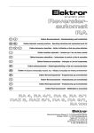
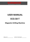
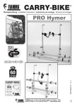
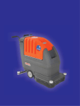
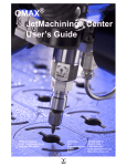
Bm20y EUROBOOR FOR PROFESSIONALS BY PROFESSIONALS USER MANUAL EBM.360 CORDLESS Magnetic Drilling Machine SERIAL NO.____________ DATE OF PURCHASE __________ 1 Congratulations on your purchase of the Euroboor EBM.360 CORDLESS Magnetic Drilling Machine. Your model is designed to produce superior holes quickly and efficiently. Through years of experience, constant innovation and development, Euroboor BV is committed to provide you with metal cutting tools and products to help you be more productive. Before operating your new magnetic drilling machine, please read all instructions first. These include the Operator’s Manual and Warning Label on the unit itself. With proper use, care, and maintenance, your model will provide you with years of effective hole drilling performance. TO REDUCE THE RISK OF INJURY USER MUST READ AND UNDERSTAND ALL INSTRUCTIONS EUROBOOR BV Kryptonstraat 110 2718 TD Zoetermeer Netherlands T +31 79 361 49 90 F +31 79 361 49 89 [email protected] www.euroboor.com 2 Fig. 1 3 Symbol Term, meaning Explanation Read documentation Be absolutely sure to read and understand the enclosed documentation such as Instruction Manual and the General Safety Instructions. Wear ear protection Use ear protection during operation. Wear eye protection Use eye-protection(safety goggle) during operation. Danger/warning/caution Observe the information in the adjacent text! European conformity symbol Confirms the conformity of the power tool with the directives of the European Community. Product with basic insulation and exposed (touchable), conductive parts additionally connected to the protective earth conductor. Class of protection I mm Millimeter Unit of measure for length, width, height or depth kg Kilogram Unit of measure for the mass V Volt Unit of measure for the electric voltage A Ampere Unit of measure for the electric current intensity W Watt Unit of measure for the output N Newton Unit of measure for the force min Minutes Unit of measure for the time no No-load speed Revolution speed at no-load 1/min per minute Unit of measure for number of revolutions, strokes, impacts or oscillations per minute. 4 GENERAL POWER TOOL SAFETY WARNINGS Do not use this power tool before you have thoroughly read and completely understood this Instruction Manual and the “General Safety Instructions”, including the figures, specifications, safety regulations and the signs indicating DANGER, WARNING and CAUTION. WARNING: When using electrical tools basic safety precautions should always be followed to reduce the risk of fire, electrical shock and personal injury including following. Please also observe the relevant national industrial safety regulations. Non-observance of the safety instructions in the said documentation can lead to an electric shock, burns and/or severe injuries. This Operator’s Manual and the “General Safety Instructions” should be kept for later use and enclosed with the power tool, should it be passed on or sold. WORK AREA 1. Keep your work area clean and well lit. Cluttered benches and dark areas invite accidents. 2. Do not operate magnetic drilling machine in explosive atmospheres, such as in the presence of flammable liquids, gases or dust. Magnetic drilling machine may create sparks which may ignite the dust or fumes. 3. Keep bystanders, children, and visitors away while operating a magnetic drilling machine. Distractions can cause you to lose control. ELECTRICAL SAFETY 1. Magnetic drilling machine plugs must match the outlet. Never modify the plug in any way. Do not use any adapter plugs. 2. Avoid body contact with grounded surfaces such as pipes, radiators, ranges and refrigerators. There is an increased risk of electric shock if your body is grounded. 3. Do not expose magnetic drilling machines to rain or wet conditions. Water entering a machine will increase the risk of electric shock. 4. Do not abuse the cord. Never use the cord to carry the magnetic drilling machine or pull the plug from an outlet. Keep cord away from heat, oil, sharp edges or moving parts. Replace damaged cords immediately. Damaged cords increase the risk of electric shock. 5. When operating a magnetic drilling machine, use an extension cord suitable for outdoor use. Use of a cord suitable for outdoor use reduces the risk of electric shock. 6. If operating a magnetic drilling machine in a damp location is unavoidable, use a residual current device (RCD) protected supply. Use of an RCD reduces the risk of electric shock. PERSONAL SAFETY 1. Stay alert, watch what you are doing and use common sense when using a magnetic drilling machine. Do not use machine while tired or under the influence of drugs, alcohol, or medication. A moment of inattention while operating magnetic drilling machines may result in serious personal injury. 2. Dress properly. Do not wear loose clothing or jewelry. Contain long hair. Keep your hair, clothing and gloves away from moving parts. Loose clothes, jewelry, or long hair can be caught in moving parts. 3. Avoid accidental starting. The EUROBOOR EBM.360 cordless magnetic drilling machine is equipped with SENSORTECH to avoid accidental starting. 4. Never place hands, fingers, gloves or clothing near cutting area or rotating machine parts. 5 5. Remove adjusting keys or switches before turning the machine on. A wrench or a key that is left attached to a rotating part of the machine may result in personal injury. 6. Mount the span guard before operating a magnetic drilling machine. Span guard prevents loose clothes, jewelry and/or long hair for being caught in the moving parts. 7. Do not overreach. Keep proper footing and balance at all times. Proper footing and balance enables better control of the magnetic drilling machine in unexpected situations. 8. Use safety equipment. Always wear eye protection. Dust mask, non-skid safety shoes, hard hat, or hearing protection must be used for appropriate conditions. 9. Always use supplied safety chain during any work on non-horizontal components. Mounting can release. MACHINE USE AND CARE 1. When using the machine on non-horizontal surfaces, you must use cutting paste. Do not use oil because the oil can drip into the motor unit. 2. During machine operations, the annular cutter must be cooled and lubricated with good quality cutting or lubrication oil. Remove the slug from the annular cutter after each hole. Caution, the slug may be hot! 3. Use clamps or other practical way to secure and support the work piece to a stable platform. Holding the work piece by hand or against your body is unstable and may lead to loss of control; 4. Do not use machine if switch does not turn it on or off. Any tool that cannot be controlled with the switch is dangerous and must be repaired. For electrical failures always send the machine to Euroboor or it’s authorized dealers for repair; 5. Disconnect the plug from the power source before making any adjustments, changing accessories, or storing the tool. Such preventive safety measures reduce the risk of starting the tool accidentally. 6. Store idle Magnetic drilling machines out of reach of children and other untrained persons. Tools are dangerous in the hands of untrained users. 7. Maintain machines with care. Keep cutting tools sharp and clean. Properly maintained tools, with sharp cutting edges are less likely to bind and are easier to control. 8. Check for misalignment or binding of moving parts, breakage of parts, and any other condition that may affect the machine operation. If damaged, have the tool serviced before using. Many accidents are caused by poorly maintained tools. 9. Use only accessories that are recommended by Euroboor BV for your model. Accessories that may be suitable for one machine, may become hazardous when used on another machine. SERVICE 1. Tool service must be performed only by qualified repair personnel. Service or maintenance performed by unqualified personnel could result in a risk of injury. 2. When servicing a tool, use only identical replacement parts. Follow instructions in the Maintenance section of this manual. Use of unauthorized parts or failure to follow Maintenance Instructions may create a risk of electric shock or injury. 3. When using this machine, you MUST wear ear and eye protection. 6 ADDITIONAL SPECIFIC SAFETY RULES FOR MAGNETIC DRILLING MACHINES • Keep your fingers well out of the drill area; • Avoid touching the drilled core that is automatically ejected by the centering pin when the working procedure is finished. Contact with the core when it is hot, or if it falls, can cause personal injuries; • Always use the drill guard. Before turning on machine ensure the guard is closed securely; • Always use the safety strap; • The magnetic drilling machine is suitable for use on steel with a thickness of at least 10 mm, with zero air gap between the magnet core surface and the mounting surface. Curvature, coats of paint and surface irregularities will create an air gap. Keep the air gap to a minimum; • Always place the machine on a flat surface; Do not clamp the magnetic drilling machine on small or irregularly shaped objects; • Always place the machine on a surface that is clear of shavings, chips, swarf and surface dirt; • Keep the magnet clean and free of debris and swarf; • Do not turn on the machine until it has been mounted and installed according to these instructions; • Do not turn on the machine before having checked that the magnetic stand has been tightened firmly to the mounting surface; • Adjust the table so cutter does not extend into the work piece before drilling. Do not perform any design, assembly or construction activities on the work piece while the machine is turned on; • Before turning on the machine, make sure the accessory has been mounted correctly; • Always use the recommended speed for the accessories and the material; • Do not use the machine on the same work piece on which electric welders are being used; • Use only an appropriate cutting fluid. Use a general non-oil-based metal cutting coolant diluted with water; • Do not use liquid cutting fluids while drilling vertically or overhead. Dip the cutter in cutting paste or apply an appropriate spray for these applications; • Do not pour cutting fluid into the reservoir while it is mounted in the bracket. Do not allow cutting fluid to enter the drill motor; • Before use, ensure movable chuck guard operates properly and is securely tighten on the magnet with the enclosed bolts; • Ensure that metal chips or resinous residue cannot lead to blockage of the function; • In case of jammed cutter disconnect the machine from the power supply, remove the reason for the jam before turning on the machine again. RESIDUAL RISKS In spite of the application of the relevant safety regulations and the implementation of safety devices, certain residual risks cannot be avoided. These are: Impairment of hearing Risk of personal injury from flying particles Risk of burns due to accessories becoming hot during operation Risk of personal injury due to prolonged use. 7 MARKINGS ON THE MACHINES The following pictograms are shown on the tool: Read instruction manual before use. Wear ear protection in areas with noise emissions > 80 db(A). Wear eye protection. POSITION Serial number The Serial Number, which also includes the type of machine, the year and month of manufacturing and identification number, is engraved on the frame, magnet and the motor unit. Example: 360 12 11 001 Model type Year of Manufacture Month of manufacture Identification number Package Contents The package contains: 1 Magnetic drilling machine 1 Carrying case 1 Drill guard 3 Handles 1 Allen Key 2.5 1 Allen Key 4 1 Allen Key 5 1 Wrench 8 1 Lubrication system 1 Safety chain/strap 1 Cutting oil 1 Operators manual 1 Exploded drawing 1 Safety Ear Protection 1 Safety Goggles 1 Safety Gloves 8 TECHNICAL DATA EBM.360 ANNULAR CUTTERS TWIST DRILLS MAX. DEPTH OF CUT LENGTH WIDTH HEIGHT STROKE WEIGHT MAGNET (L x W x H) MAGNETIC FORCE BATTERY CHARGE TIME SPEED (no load) SPINDLE CHARGER AVAILABLE ø 12 - 36 mm ø 1 – 13 mm 55 mm 297 mm 112 mm 420 - 650 mm 230 mm 15 kg 160 x 80 x 42 mm 1700 kg 37V / 7 Ah Li-Ion 90 minutes (I) 506 minˉ¹ 19,05 mm Weldon 230V AC Emission values for sound and vibration (Two-figure – specifications as per ISO 4871) Sound emission Measured A-weighted sound power level LwA (re 1 pW), in decibels Measuring uncertainty KwA, in decibels 89 3 A-weighted emission pressure power level measured at the workplace LpA (re 20 μPa), in decibels Measuring uncertainty KpA, in decibels 89 3 Vibration emission Rated acceleration, in m/s² Measuring uncertainty K, in m/s² 0.5 1.5 REMARK: The sum of the measured emission value and respective measuring inaccuracy represents the upper limit of the values that can occur during measuring. Wear ear protection! For measurement values obtained according to the respective product standard, see the last page of this Operator’s Manual. 9 DESCRIPTION (fig. 1) WARNING: Never modify the power tool or any part of it. Damage or personal injury could result. 1. 2. 3. 4. 5. 6. Safety Guard Feed handle Cooling system tank Magnetic stand Magnet switch Motor switch INTENDED USE This magnetic drilling machine is intended for commercial use as a drilling machine for drilling materials with a magnetisable surface using annular cutters, twist drills and countersinks in a weather-protected environment using the application tools and accessories recommended by EUROBOOR. The magnetic drilling machine can be used horizontally, vertically or overhead. DO NOT use under wet conditions or in presence of flammable liquids or gases. DO NOT let children come into contact with the machine. Supervision is required when inexperienced operators use this machine. ASSEMBLY AND ADJUSTMENTS WARNING: To reduce the risk of injury, turn unit off and disconnect machine from power source before installing and removing accessories, before adjusting or changing set- ups or when making repairs. Be sure the switch is in the OFF position. An accidental start-up can cause injury. INSTALLING THE MACHINE (FIG. 1) 1. Assemble the feed handle. 2. Mount the drill guard. 3. Fit the lubrication system if necessary. 4. Place the machine on a clean, level and solid surface. Remove any particles that will obstruct full contact between the magnetic stand and the mounting surface. 5. Fit the safety chain (in vertical or overhead drilling applications). INITIAL OPERATION Check the machine for possible damage; Before using the machine, you must carefully check protective devices or slightly damaged components to ensure they are operating perfectly and as intended. Check that moving are in perfect working order and do not jam and check whether parts are damaged. All parts must be correctly installed and fulfill all conditions necessary to ensure perfect operation of the machine. Damaged protective devices and parts must be repaired or replaced according to specifications by EUROBOOR of any authorized EUROBOOR dealer. 10 BATTERY PACK Charge the battery before use. If performance diminishes, recharge the battery pack. The ideal storage temperature is between 10° and 30°C. Li-ion battery packs (37 V) have a capacity and signal display: Press button and the charge level is displayed by the LED lights; If red LED is displayed, the battery pack is almost flat and must be recharged; If all LED lights are flashing, the battery pack is to warm. Allow the battery pack to cool down. REMOVING AND INSERTING THE BATTERY PACK Removal Press both buttons on the side of the battery pack and take out the battery pack from its position. Inserting Slide in the battery pack completely until it engages. MOUNTING THE DRILL GUARD (FIG. 1) 1. Hold the guard in front of the magnet, aligning the slots in the guard with the holes in the magnet. 2. Fit the screws into the hole located in the side of the magnet. WARNING: Always use the Safety guard. FITTING THE LUBRICATION SYSTEM (FIG. 1) The lubrication system can be used for horizontal drilling applications (the drill being used vertically). Hold the cooling tank against the bracket on the slide and push it in its place. Connect the hose to the nipple on the spindle drive shaft. In order to use the lubrication system, it must be filled with a sufficient amount of cutting fluid. 1. Make sure the flow regulator is closed; 2. Unscrew the cap; 3. Fill the container with cutting fluid; 4. Screw the cap back on. WARNING: Do not use the lubrication system in vertical or overhead drilling applications. Instead use Euroboor cutting paste 11 FITTING THE SAFETY CHAIN/STRAP For drilling carried out on angled and vertical surfaces and overhead, the magnetic drilling machine must be secured with the safety strap/chain supplied to prevent it from falling, even if the magnet malfunctions. WARNING: Check the safety strap for damage. If the safety strap is damaged, replace it immediately. 1. Pass the safety chain through the opening near the handle; 2. Wrap the chain around the work piece; 3. Securely close the chain using the lock. The safety chain does not replace the magnetic force of the magnetic drilling machine: it is simply used to secure against falling in the event of a magnet malfunction. WARNING: Always use the safety chain when using machine vertically or in up-side-down position. INSERTING AND REMOVING AN ACCESSORY (FIG. 1) Remove the battery pack from the machine before any adjustments, conversions or servicing are performed. Do not use deformed or damaged tools. Before use, always check tools such as core drills for deformities or damage. Do not use accessories that have not been specified or recommended by Metabo for this machine. The ability to attach the accessory to your machine does not guarantee safe operation. Securing or positioning a tool incorrectly can cause hazardous situations due to parts breaking or being blown off. If the tool is jammed: Press the RED switch “O” to switch off the motor unit. Remove the annular cutter from the borehole. The tool holder accepts annular cutters with a 19,05 mm Weldon shank with one or more flats. WARNING: The teeth of a cutter are very sharp and can be dangerous. 1. 2. 3. 4. 5. In order to fit an annual cutter it is necessary to remove the guard (1); Slide the pilot pin through the hole in the center of the cutter shank; Insert the shank of the accessory as far into the tool holder as possible; Tighten the two Allen screws with Allen key; To remove the accessory, loosen the Allen screws and take out the cutter. 12 PRIOR TO OPERATION Try a few simple projects using scrap material until you develop a “feeling” for the machine. WARNING: Always observe the safety instructions and applicable regulations. WARNING: To reduce the risk of serious personal injury, turn tool off and disconnect tool from power source before making any adjustments or removing/installing attachments or accessories. MAGNETIC BASE Material of minimum 10 mm thickness is required for the magnet to work the best. The attachment force generated by the magnet depends on various factors. Thickness of the material the magnet is placed on; Paint or coating of the material the magnet is placed on; Metal chips, oil or other dirt under the magnet. If the LED light of the Magnet Switch (see page 14) lights up GREEN, the magnet is generating sufficient attachment force. If this switch alternately lights up RED en GREEN together with a beeping sound, the magnet does not generate sufficient attachment force and the Motor will not start (for safety reasons). CAUTION: EUROBOOR EBM.360 does not allow turning on the motor if LED light in the Magnet Switch alternately lights up RED/GREEN. If turning on the machine is possible while this happens, please return the machine to EUROBOOR or any authorized dealer. We would like to point out that this is only an indication and not a certainly that the magnet will not release from the material. Euroboor accepts no liability ensuring from the magnet indicator not functioning or functioning poorly. Make sure that the magnet attaches tightly to the work piece before turning on the motor unit of the magnetic drilling machine. Euroboor magnets have 2 coils; make sure that both coils are in contact with the material. Do not connect any other machines to the electrical outlet the magnetic drilling machine is plugged into, as it may result in the loss of magnetic force. Always use the safety chain/strap included. Drilling over head is extremely dangerous and is not recommended. For the use of magnetic drilling machines on pipes, not-flat or non-magnetic materials, we refer to our brochure or our website www.euroboor.com where several vacuum tightening systems and pipe clamping systems are mentioned. 13 THE CONTROL PANEL The control panel on your magnetic drilling machine is designed for maximum operating facility and safety. 1 - The ON Switch (GREEN): This (upper) switch is used to switch the motor unit On (“I“); 2 – The OFF Switch (RED) This (lower) switch is used to switch the motor unit Off (“O“); 3 - The Magnet Switch (WHITE): This switch is used to turn on the main power and also to switch the magnet On and Off. Also this switch indicates if the generated magnetic force is enough for the tool to operate safely. The indicator is enclosed in the magnet switch and has two collors: GREEN – SAFE for use Alternately lightning up RED and GREEN and making a beeping sound – Not safe for use In order to operate properly, the machine has to be turned on following the procedure as described below. ACTIVATING THE MAGNET Connect the machine to the work piece. To activate the magnet, press de WHITE switch (Fig. 2 – 3). The switch will be lit GREEN if the generated magnetic force is sufficient to work safely. If the switch starts flashing RED and GREEN and making a beeping noise, there is not enough magnetic force and the motor is not able to start. To deactivate the magnet, press the same button (Fig. 2 - 3) again. TURNING THE MOTOR ON AND OFF The drill motor can only be switched on when the magnet is activated. To turn ON the motor, press the GREEN button “I”(Fig. 2 - 1), the WHITE magnet switch will be lit yellow. To turn OFF the motor, press the RED button “O” (Fig. 2 - 2). 14 DRILLING A HOLE Now that you have read the explanatory information and safety recommendations above, you are ready to actually start drilling. Follow these 10 steps for best drilling result : 1 2 Use the tip of the pilot pin to determine the center of the hole to be drilled. Turn the magnet on and verify that the drill is in the right position and that the machine is pushed tight against the work piece. 3 If your machine is equipped with a auto coolant system, open the valve to release the oil. If your machine does not have a auto coolant system, fill the holes of the spindle with oil. 4 Turn the motor on at the highest setting and allow it to run at full speed. 5 Turn the arms to start drilling. Apply only a slight pressure when the Annular Cutter touch the metal. Do not push the Annular Cutter with force into the metal. 6 Apply a regular pressure while drilling. The drilling performance does not improve by putting more pressure on the feed handles. Too much pressure will overload the motor and your Annular Cutter will break or will worn sooner. Let the cutter do the job and give it time to cut the metal !!! For a hole 32 mm/ 1-1/4” in a 25 mm (1”) steel plate, EUROBOOR recommends one minute drilling time. 7 Adjust the oil supply when necessary, if your drill does not have a auto coolant system, stop drilling regularly, refill the holes of the spindle and continue drilling. 8 Apply less pressure when the drill cuts through the material. 9 Turn the arms to put the motor in highest position and turn off the motor unit. 10 Remove the burr, metal chips and clean the cutter and surface without getting injuries. Caution : The metal piece drilled out can be sharp and very hot!! DRILLING WITH ANNULAR CUTTERS Annular cutters only cut material at the periphery of the hole, rather than converting the entire hole to shavings. As a result, the energy required to make a hole is lower than for a twist drill. When drilling with an annular cutter, it is not necessary to drill a pilot hole. WARNING: Do not touch the cutter or the parts close to the cutter immediately after operation, as they may be extremely hot and cause burns to the skin. Ensure nobody is in the work area where the metal core is ejected. DRILLING CONDITIONS The ease with which material can be drilled depends on several factors including tensile strength and abrasion resistance. Whilst hardness and/or strength is the usual criterion, wide variations in machineability can exist among material showing similar physical properties. The drilling conditions are dependent on requirements for tool life and surface finish. These conditions are further restricted by the rigidity of the tool and the work piece, lubrication and machine power available. The harder the material, the lower the cutting speed. Some materials of low hardness contain abrasive substances leading to rapid cutting edge wear at high speeds. Feed rates are governed by rigidity of set-up, volume of material to be removed, surface finish and available machine power. 15 LUBRICATION IN HORIZONTAL APPLICATIONS Adjust the fluid flow as required using the flow regulator; Add more cutting fluid if the shavings (metal chips) become blue. VERTICAL AND OVERHEAD APPLICATIONS Dip the cutter in cutting paste or apply an appropriate spray. LUBRICATING THE FEED TRAVEL The feed travel should be lubricated periodically with grease to ensure smooth operation. Raise the motor unit to the highest position possible. Lubricate the dove-tail guide way at both sides. Lubricate the gear rack. After repeated use, the gear rack may become loose. If necessary, adjust the 5 self-locking set screws at the left side. Tighten screws in series until the gear rack moves freely in the dove-tail guide but does not allow the motor to wobble. Cleaning CAUTION: Blow dirt and dust out of the main housing with dry air as often as dirt is seen collecting in and around the air vents. Wear approved eye protection and approved dust mask when performing this procedure. CAUTION: Never use solvents or other harsh chemicals for cleaning the non-metallic parts of the tool. These chemicals may weaken the materials used in these parts. Use a cloth dampened only with water and mild soap. Never let any liquid get inside the tool; never immerse any part of the tool into a liquid. Optional Accessories WARNING: Since accessories, other than those offered by EUROBOOR, have not been tested with this product, use of such accessories with this tool could be hazardous. To reduce the risk of injury, only EUROBOOR recommended accessories should be used with this product. Consult your dealer for further information on the appropriate accessories. 16 MAINTENANCE Your EUROBOOR power tool has been designed to operate over a long period of time with a minimum of maintenance. Continuous satisfactory operation depends upon proper tool care and regular cleaning. CAUTION: To reduce the risk of injury, turn unit off and disconnect machine from power source before installing and removing accessories, before adjusting or changing set- ups or when making repairs. Be sure the switch is in the OFF position. An accidental start-up can cause injury. Just as every magnetic drilling machine with moving parts, your Euroboor magnetic drilling machine also needs regular maintenance service. A few recommendations follow : VISUALLY CHECK THE MACHINE FOR DAMAGE Machine must be checked before operation for any signs of damage that will affect the operation of the machine. Particular notice must be taken of the mains cable, if the machine appears to be damaged it should not be used failure to do so may cause injury or death. CAUTION : Clean all dirt, dust, metal chips and burrs of your magnetic drilling machine OPERATION OF THE MACHINE The machines operation must be checked to ensure that all components are working correctly. Replace any defective parts immediately. This prevents properly function parts from being damaged. CARBON BRUSHES Brushes should be checked to make sure there is no abnormal wear present. This should be checked at least once a week if used frequently. If the carbon brush has worn more than 2/3 the original length the brushes should be changed. Failure to do so may cause damage to the machine. CHECK MAGNETIC BASE Before every operation the magnetic base should be checked to make sure that the base is flat and there is no damage present. An uneven magnet base will cause the magnet not to hold as efficiently and may cause injury to the operator. CHECK MACHINES GREASE The gearbox grease should be checked once a month to ensure all moving components are covered to prevent wear. The grease should be changed at least once a year to ensure you gain the best from the machine. CHECK ARMATURE This should be checked at least 1 per month to check that there are visual signs of damage to the body or to the commutator. Some signs of wear will be seen on the commutator over a period of time this is normal as this is the part that comes in contact with the brushes but any signs of abnormal damage and the part should be replaced. 17 ADJUSTMENT OF SLIDE An essential requirement of the machine is that the slide can move in a smooth and controlled manner, free of lateral movement and vibration. This situation can be maintained by periodic adjustment of the slide and is accomplished in the following manner: 1. Place the machine in an upright position and, by means of the capstan, raise the slide to its highest position. Clean the brass rail strips and apply a small amount of light machine oil to the wear surfaces. 2. Commencing with the top screw, loosen both setting nut (#4 on spare part drawing) with included wrench 8 and the setting screw (#5 on spare part drawing) with included Allen key 2.5. Then gently feed in setting screw until slight resistance is encountered. Follow your way down adjusting all setting nuts and screws. 3. Operate the slide up and down a few times to test the movement and make any further necessary adjustments. Try to ensure that all the screws are exerting a uniform pressure on the slide from top to bottom. A perfectly adjusted slide will operate freely up and down without any sideways movement. REPAIR, MODIFICATION AND INSPECTION Repair, modification and inspection of Euroboor Magnetic drilling machines must be done by EUROBOOR or an EUROBOOR authorized dealer. The spare parts list will be helpful if presented with the machine to the Euroboor dealer for service when requesting repair or other maintenance. Euroboor machines are constantly being improved and modified to incorporate the latest technological advancements. Accordingly, some parts (i.e. part numbers and/or design) may be changed without prior notice. Also, due to Euroboor's continuing program of research and development, the specifications of machines are subject to change without prior notice. 18 TROUBLE SHOOTING Magnet and motor do not function - Battery is low - Battery too hot - Work piece too thin (min. 10 mm) - The magnet switch is not connected to the power supply - Damaged or defective wiring - Defective magnet switch - Defective Control Unit Magnet does function, the motor does not work - Damaged or defective wiring - Carbon brushes are stuck or worn out - Defective magnet switch - Defective On / Off switch - Defective Control Unit - Defective armature and/or field - Defective magnet - Defective wiring of magnet - Defective Control Unit - Clearance in the guide - Bent spindle - Shaft extending from the motor is bent - Bent pilot pin - Bent spindle - Shaft extending from the motor is bent - Triangular guide not mounted straight - Dirt between spindle and triangular guide - Damage or defective relais in control unit Magnet does not function, the motor does Annular cutters break quickly, holes are bigger than the hole cutter Motor running roughly and/or seizing up Motor starts running when magnet switch is turned on Motor making a rattling sound Motor humming, big sparks and motor has no force Motor does not start or fails. Guiding takes a great deal of effort - Gear ring (bottom of the armature) worn out - Gear(s) worn out - No grease in gear box - Armature damaged (burned) - Field burned - Carbon brushes worn out - Damaged or defective wiring - Dirt in sensor Speed Control Unit - Defective or loose magnet on top of armature - Damaged or defective (sensor) Speed Control Unit - Damage to Armature or field coil - Damaged or defective carbon brushes - Guide is set too tight - Guide is dry, needs to be greased - Guide/gear- rack/rotation system dirty or damaged 19 Insufficient magnetic force - Damaged or defective wiring - Bottom of magnet not clean and dry - Bottom of magnet not flat - Work piece is not bare metal - Work piece is not clean or flat - Work piece is less than 10 mm (too thin) - Defective Control Unit - Defective magnet Frame is electrified - Damaged / defective wiring - Defective magnet - Motor seriously dirty Fuse blows when magnet switch is - Damaged or defective wiring turned on - Wrong value fuse - Defective magnet switch - Defective Control Unit - Defective magnet Fuse blows when motor is started - Damaged or defective wiring - Wrong value fuse - Motor running roughly - Defective Armature and / or Field - Carbon brushes worn out - Defective Control Unit Rotation system free stroke too - Loose or defective gear-rack long - Defective rotation system NOTE: Please contact EUROBOOR if there is machine failure and the problem cannot be saved with one of the above solutions!! PROTECTING THE ENVIRONMENT Separate collection. This product must not be disposed of with normal household waste. Should you find one day that your EUROBOOR product needs replacement, or if it is of no further use to you, do not dispose of it with household waste. Make this product available for separate collection. Separate collection of used products and packaging allows materials to be recycled and used again. Re-use of recycled materials helps prevent environmental pollution and reduces the demand for raw materials. Local regulations may provide for separate collection of electrical products from the household, at municipal waste sites or by the retailer when you purchase a new product. 20 Spare parts & Exploded view of EBM.360 Drawing Article nr. Description 1 2 3 4 5 6 7 8 9 10 11 12 13 14 15 16 17 18 19 20 21 22 23 24 25 26 27 28 29 30 31 32 33 360.1001 360.1002 360.1003 360.1004 360.1005 360.1006 360.1007 360.1008 360.1009 360.1010 360.1011 360.1012 360.1013 360.1014 360.1015 360.1016 360.1017 360.1018 360.1019 360.1020 360.1021 360.1022 360.1023 360.1024 360.1025 360.1026 360.1027 360.1028 360.1029 360.1030 360.1031 360.1032 360.1033 Screw Motorhousing left side Label (Left side) Motorhousing right side Label (Right side) Sensor Holder Bolt M5x60 Motor Assembly Pin 6x60 Lower Inner Gear Plate Gasket Bearing 608 1st Gear Spindle Gear Bearing 626ZZ Adaptor ring Bearing 6003DDU Gear Casing Spindle Drive Shaft Bolt M5x10 Tank holder Slide Washer 6 Bolt M6x20 Bolt M6x14 Steady Spindle Rack Screw Washer Brass rail (Left side) Brass rail (Right side) Motor cable protection screw Drawing Article nr. Description 34 35 36 37 38 39 40 41 42 43 44 45 46 47 48 49 50 51 52 53 54 55 56 57 58 59 60 61 62 63 64 65 360.1034 360.1035 360.1036 360.1037 360.1038 360.1039 360.1040 360.1041 360.1042 360.1043 360.1044 360.1045 360.1046 360.1047 360.1048 360.0001 360.1050 360.1051 360.1052 360.1053 360.1054 360.1055 360.1056 360.1057 360.1058 360.1059 360.1060 360.1061 360.1062 360.1063 360.1064 360.1065 Pressing strip Wiring cover Frame Magnet Setting Screw Setting Nut Motorcable cover Wire #1 Wire #2 Wire #3 Wire #4 Connector Coupling nut Capstan hub Arm Battery Pack Bolt Screw Battery Contact board Connector Connector Battery slide base On Switch Off Switch Magneet Switch Wiring + connector Wiring + connector Front Panel Plate Crimp nut Screw Control Unit Rear Panel Plate 21 EXPLODED VIEW EBM.360 22 23 SAFETY RULES 37V/7Ah LITHIUM-ION BATTERY PACK Read all instructions. Failure to follow all instructions listed below may result in electric shock, fire and/or serious injury. The term “power tool” in all of the warnings listed below refers to your mainsoperated (corded) power tool or battery-operated (cordless) power tool. Remove the battery pack from the machine before any adjustments, conversions or servicing are performed. Before fitting the battery pack, make sure that the machine is switched off. Do not open the battery packs Do not place the battery pack or cells on or near fires, heaters, other high temperature locations, or apply heat to the battery. Do not pierce the battery with any sharp objects, strike the battery with a hammer, tools, or heavy objects, step on the battery pack, or otherwise damage the outer casing. Do not subject the battery pack to strong impacts or shocks. Do not expose the battery to water or any other type of liquid, or allow the battery to get wet. Do not leave the battery in direct sunlight, and avoid storing spare battery packs inside cars in extreme hot weather. Doing so may cause the battery to generate heat, rupture, or ignite. Using the battery in this manner may also result in a loss of performance and a shortened life expectancy. When a battery becomes too hot, the built-in protection circuitry is activated, preventing the battery from charging further. Heating the battery can destroy the safety devices, and can cause additional heating, rupture or ignition of the battery cells. Never short-circuit, reverse polarity, disassemble, damage or heat the battery pack over 100°C (212°F). If an exposed lithium-ion battery does start a fire , it may burn even more violently if it comes into contact with water or even the moisture in the air. DO NOT THROW WATER ON A BURNING LI-ION BATTERY! A class C fire extinguisher must be used. Do not use the Battery Pack if the Battery Pack casing is broken or if a Battery Pack emits an unusual odor, smoke, or excessive heat or leaks any substance. Avoid contact with any substance seeping from the Battery Pack. Keep out of reach of children and pets. Exposure to Battery Pack voltage could result in death or serious injury. The cells within the Battery Packs contain toxic substances. Do not attempt to open Battery Packs. Do not insert any object into the Battery Packs or use any device to pry at the Battery Pack casing. If you insert an object into any of the Battery Packs’ ports or openings you could suffer electric shock, injury, burns, or cause a fire. Attempting to open the Battery Pack casing will damage the casing and could release toxic and harmful substances, and will render the pack unusable. If battery fluid leaks out and comes into contact with your skin, rinse immediately with plenty of water. If battery fluid leaks out and comes into contact with your eyes, wash them with clean water and seek medical attention immediately As with all rechargeable batteries, do not charge near flammable materials Do not disassemble or modify the battery pack . The battery contains safety and protection devices which, if damaged, may cause the battery to generate heat, rupture or ignite. Any modification may damage the battery pack or cells and will invalidate any warranty claim. 24 If you happen to get any electrolyte from the cells on your skin, wash thoroughly with soap and water. If in your eyes, do not rub. Rinse thoroughly with water and seek medical OPERATION CAUTION: If at any point during the charging process none of the LEDs are lit, remove the battery pack from the charger to avoid damaging the product. DO NOT insert another battery. Return the charger and battery to your nearest service center for service or replacement. CAUTION: Charge in a well ventilated area. Do not block charger vents. Keep them clear to allow proper ventilation. EUROBOOR BV 37V/7Ah lithium-ion batteries are designed with features that protect the lithium-ion cells and maximize battery life. Under some operating conditions, these built-in features may cause the battery and the tool it is powering to act differently from nickel-cadmium batteries. During some applications, the battery electronics may signal the battery to shut down, and cause the tool to stop running. To reset the battery and tool, release the trigger and resume normal operation. NOTE: To prevent further shut down of the battery, avoid forcing the tool. Switching to a lower speed will also prevent shut down. If releasing the trigger does not reset the battery and tool, the battery pack is depleted. If depleted, the battery pack will begin charging when placed on the lithium-ion charger. A fully discharged battery pack with a temperature between 0° (32°F) and 65° (150°F) will charge in about an hour. Use battery pack only with the recommended EUROBOOR charger (360.0500). Connect the charger to a power supply. Make sure the power supply is normal household voltage, 220 volts, AC only, 60 Hz. Attach the battery pack to the charger by aligning the raised ribs on the battery pack with the grooves in the charger, then slide the battery pack onto the charger. See Figure 1. Do not place the charger and battery pack in an area of extreme heat or cold. They will work best at normal room temperature. Note: The charger and battery pack should be placed in a location where the temperature is more than 10° (50°F) but less than 38° (100°F). The battery pack will become slightly warm to the touch while charging. This is normal and does not indicate a problem. After charging is complete, the green LED will remain on until the battery pack is removed from the charger or charger is disconnected from the power supply. When batteries become fully charged, unplug the charger from the power supply and remove the battery pack. 25 CHARGING A HOT BATTERY PACK If the battery pack is above normal temperature range, the red LED will begin flashing and the green LED will be off. When the battery pack cools down to approximately 150°F, the charger will automatically begin fast charge mode. CHARGING A COOL BATTERY PACK If the battery pack is below normal temperature range, the red LED will begin flashing and the green LED will be off. When the battery warms to a temperature of more than 32°F, the charger will automatically begin charge mode. COLD WEATHER OPERATION The lithium-ion battery pack can be used in temperatures down to -4°F. Put the battery pack on a tool and use the tool in a light duty application. After about a minute, the pack will have warmed up and begin operating normally. MAINTENANCE This battery pack is equipped with lithium-ion rechargeable batteries. Length of service from each charging will depend on the type of work you are doing. These batteries have been designed to provide maximum trouble-free life. However, like all batteries, they will eventually wear out. Do not disassemble battery pack and attempt to replace the batteries. Handling of these batteries, especially when wearing rings and jewelry, could result in a serious burn. To obtain the longest possible battery life from RIDGID lithium-ion batteries, we suggest the following: Remove the battery pack from the charger once it is fully charged and ready for use. For battery pack storage longer than 30 days: Store the battery pack where the temperature is below 80°F and away from moisture. Store battery packs in a 30%-50% charged condition. Every six months of storage, charge the pack as normal. BATTERY PACK REMOVAL AND PREPARATION FOR RECYCLING To preserve natural resources, please recycle or dispose of batteries properly. This product contains lithium-ion batteries. Local, state or federal laws may prohibit disposal of lithium-ion batteries in ordinary trash. Consult your local waste authority for information regarding available recycling and/or disposal options. WARNING: Upon removal, cover the battery pack’s terminals with heavy-duty adhesive tape. Do not attempt to destroy or disassemble battery pack or remove any of its components. Lithium-ion batteries must be recycled or disposed of properly. Also, never touch both terminals with metal objects and/or body parts as short circuit may result. Keep away from children. Failure to comply with these warnings could result in fire and/or serious injury. 26 27 BATTERY CHARGER CHARGING THE BATTERY On the battery charger there are two lights (RED and GREEN) When the RED light flashes the battery is charged (2% - 80%). When the GREEN light flashes the last 20% of the battery is charged. When the green light stops flashing and remains lit green, the battery is fully charged and ready for use. CAUTION: When both the RED and GREEN light are simultaneously lit than either the battery charger or the battery it’s self is too hot. If the RED and GREEN light on the charger are alternately flashing RED/GREEN, there is a general error. BATTERY CHARGING TEMPERATURE PROTECTION If the battery reaches 50℃, the charger will stop charging. Error signals: the RED and GREEN light are simultaneously lit RED and GREEN. The charger will start charging again if the temperature of the battery is 45℃ or less ( Over temperature recovery). SIGNALS ON THE MACHINE Signals well functioning magnetic drilling machine When the EBM.360 magnetic drilling machine is well positioned on the work piece, press the magnet (white) switch to on the magnet. The LED will flash 2x GREEN and then remain lit GREEN. When the motor is switched on (green switch), the magnet switch will be lit yellow. Signaling malfunctioning of the magnetic drilling machine When the (white) magnet switch is flashing alternately RED/GREEN together with an acoustic sound, then there is not enough magnet force or magnet is not working When the (white) magnet switch is flashing RED, the battery is low; When the (white) magnet switch is flashing YELLOW, there is over current and the motor will stop. 28