1
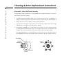
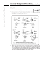
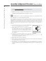
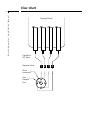
Harvard
Liquid Switch
User’s Manual
Harvard Liquid Switch
55-3438
Table of Contents
Harvard Apparatus ‘Liquid Switch’ Manual
1
SUBJECT
PAGE NO.
Table of Contents ..........................................................................................................1
General Information - Warranty and Repairs ................................................................2
Cleaning and Rotor Replacement Instructions ..........................................................3-5
Disassembly - Valves with External Spring Hardware ....................................................3
Disassembly - Valves with Preload Assembly..................................................................4
Cleaning ........................................................................................................................5
Assembly and Alignment Procedure (New or Used Rotor) ......................................6-10
Leak Detection ............................................................................................................11
Flow Chart Illustration ................................................................................................12
General Information
Harvard Apparatus ‘Liquid Switch’ Manual
2
Serial Numbers
All inquires concerning our product should refer to the serial number of the unit. Serial numbers
are located on the rear of the chassis.
Calibrations
All electrical apparatus is calibrated at rated voltage and frequency. While the flow will stay calibrated, the peak will vary.
Warranty
Harvard Apparatus warranties this instrument for a period of one year from date of purchase. At
its option, Harvard Apparatus will repair or replace the unit if it is found to be defective as to
workmanship or material.
This warranty does not extend to damage resulting from misuse, neglect or abuse, normal wear
and tear, or accident.
This warranty extends only to the original customer purchaser.
IN NO EVENT SHALL HARVARD APPARATUS BE LIABLE FOR INCIDENTAL OR CONSEQUENTIAL DAMAGES. Some states do not allow exclusion or limitation of incidental or consequential damages so the above limitation or exclusion may not apply to you. THERE ARE NO
IMPLIED WARRANTIES OF MERCHANTABILITY, OR FITNESS FOR A PARTICULAR USE, OR
OF ANY OTHER NATURE. Some states do not allow this limitation on an implied warranty, so the
above limitation may not apply to you.
If a defect arises within the one-year warranty period, promptly contact Harvard Apparatus, Inc.
84 October Hill Road, Building 7, Holliston, Massachusetts 01746-1371 using our toll free number
1-800-272-2775. Goods will not be accepted for return unless an RMA (returned materials authorization) number has been issued by our customer service department.The customer is responsible for shipping charges. Please allow a reasonable period of time for completion of repairs,
replacement and return. If the unit is replaced, the replacement unit is covered only for the
remainder of the original warranty period dating from the purchase of the original device.
This warranty gives you specific rights, and you may also have other rights which vary from state
to state.
Repair Facilities and Parts
Harvard Apparatus stocks replacement and repair parts. When ordering, please describe parts as
completely as possible, preferably using our part numbers. If practical, enclose a sample or drawing.We offer a complete reconditioning service.
CAUTION
This pump is not registered with the FDA and is not for clinical use on human patients.
Cleaning & Rotor Replacement Instructions
Harvard Apparatus ‘Liquid Switch’ Manual
3
Perform all other system checks before working on the valve. Since any contact between the interior of
the valve body and the metal of the rotor is likely to cause damage, do not take the valve apart unless the
system malfunction is definitely isolated to the valve. If disassembly is absolutely necessary, make certain
to carefully observe the instructions listed below for disassembly, cleaning and reassembly.
Disassembly - Valves with External Spring Hardware
Perform all disassembly operations in a clean, well-lighted area. Flush all hazardous or toxic materials from the valve before starting.
1.
For a valve on a standoff: Use a 7/64 hex driver to loosen the 6-32 x 5/8" socket head screw
in the clamp ring which holds the valve to the standoff tube (not the one which holds the
standoff to the actuator) and remove the valve from the actuator/standoff assembly.
For a closemount valve: Use a 7/64 hex driver to loosen the 6-32 x 5/8" socket head screw in
the clamp ring between the valve and the actuator, and remove the valve from the actuator.
2.
Using a 7/16" open wrench or nut-driver, loosen and remove the 10-32 hex nuts from the
threaded seal shaft.
3.
Slide the coil spring and washers from the shaft, taking care to note their order for reassembly later.
4.
Grasp the valve firmly and give a slight rotation to the 1/4" shaft of the rotor to break apart
the sealing surfaces. Alternatively, grip the valve with the 1/4" shaft pressed firmly into the
palm of the hand to restrict its travel and tap the end of the threaded shaft.
5.
After the sealing surfaces are broken free in the above operation, carefully pull the rotor out
of the tapered interior of the valve body.
Cleaning & Rotor Replacement Instructions
Harvard Apparatus ‘Liquid Switch’ Manual
4
Disassembly - Valves with Preload Assembly
Perform all disassembly operations in a clean, well-lighted area. Flush all hazardous or toxic materials from the valve before starting.
1.
Unscrew the preload assembly from the valve. For valves rated at pressures over 1000 psi, it is
helpful to unscrew the preload 1/2 turn before trying to unscrew the preload itself. (Figure 1)
2.
Engage the end of the rotor (Figure 2) with a pencil-type magnet.
3.
Step the actuator through several positions to break apart the sealing surfaces and carefully
withdraw the rotor form the valve body with the magnet.
4.
For a valve on a standoff: Use a 7/64 hex driver to loosen the 6-32 x 5/8" socket head screw
in the clamp ring which holds the valve to the standoff tube (not the one which holds the
standoff to the actuator) and remove the valve from the actuator/standoff assembly.
For a closemount valve: Use a 7/64 hex driver to loosen the 6-32 x 5/8" socket head screw in
the clamp ring between the valve and the actuator, and remove the valve from the actuator.
Valve Body
Preload
Assembly
End of
Rotor
Socket Adjustment
Screw
Cleaning & Rotor Replacement Instructions
Harvard Apparatus ‘Liquid Switch’ Manual
5
Cleaning
1.
Using clean dry air, blow any loose debris from the valve body and the rotor.
2.
Using a strong solvent and an optical quality lint-free wiper such as a Kimwipe, wipe away
any loosely bound seal material which may have worn free and adhered to either surface.
Avoid using halocarbon solvents if the valve is to be used in a system with electron capture
detection, since some of the solvents may persist at the trace level. Be sure to consult the
Manufacturer’s Data Safety sheet for whatever solvent is utilized.
Note: If the valve has been used with aqueous buffer solutions and some leakage has occurred, wipe the sealing surfaces of the valve with a water-moistened Kimwipe before using a nonpolar solvent to clean any seal
material still adhering to the valve’s interior.
3.
Visually inspect the interior of the valve body.The conical surface should appear uniform as
well as highly polished. If any scratches are visible between the ports or anywhere else, suggesting a potential leakage path or wear source, the valve should be returned to the factory
for regrinding. If the rotor’s sealing surface shows any scratches and/or a narrowing of the surface flow passages, replacement is necessary. If the valve body interior is in good condition, a
field replacement of the rotor may be effected using the following procedure.
Assembly & Alignment Procedure (New or Used Rotor)
Harvard Apparatus ‘Liquid Switch’ Manual
6
The valve will have either one (SD and SC types) or two (SF and ST types) rows of ports evenly
spaced around the circumference of the body. See Figure 4. In addition there will be one (SD and
SF types) or two (SC and ST types) “common” ports offset to either side of these rows.The rotor
will have either one or two flow passage(s) appearing as engraved rings around the seal, which
intersect the common port(s). Flow passage(s) perpendicular to the rings(s) connect the ring(s)
to the selected port(s).
STUW
The only configuration which does not fall within this description is the STUW. Unlike the standard ST, these have one row of port around the circumference, with two common ports offset in
the same direction. The common ports are 180° apart, so only one shows in Figure 4. Special
instructions and descriptions regarding STUW and/or SDUW valves will be highlighted in this
manner at several points in the procedures below.
The alignment procedure is a way of centering the perpendicular engraving on the selected port
by determining the point at which flow begins (when the engraving is just beginning to intersect
the port) and the point at which flow ends (when the engraving has ceased to intersect the port),
and centering the rotor between those two points.
1.
Make sure that all sealing surfaces are clean and dry.
2.
If a used rotor is to be reinstalled, clean with a light solvent and blow the passages clean with
compressed air. Discard the rotor if any scratches are visible between ports.
3.
Locate the common port offset toward the small end of the valve interior. (In SD and SC valves
this is the only common port).This port, called the alignment inlet, will be the designated inlet
throughout this procedure.
STUW
In the case of the STUW with both common ports at the same end, either will serve the current
purpose.
4.
Put a nut in the port corresponding to the last or highest numbered position:
For an electric actuator: With the valve oriented as in Figure 4, the nut goes in the port above
the alignment inlet.
For an air actuator: With the valve oriented as in Figure 4, the nut goes in the port below the
alignment inlet.
5.
Locate the flow passages(s) perpendicular to the ring(s) that go around the rotor. Note the
pin which passes through the shaft.The end of the pin on the same side of the rotor as the
flow passages(s) perpendicular to the rings will be used as a pointer. (Figure 4)
Assembly & Alignment Procedure (New or Used Rotor)
Harvard Apparatus ‘Liquid Switch’ Manual
7
STUW, SDUW
The pointer will be that end of the tab which is stamped “P”,“H” or “E”,
denoting the valve series. (Fig. 3)
POINTER
Figure 3
6.
Insert the rotor in the valve body with the pointer centered on the
nut, being careful not to touch the polished interior surface of the
valve body with any of the metal parts of the rotor.
7.
Slide the three washers (in this sequence: 3/4" OD washer,Teflon or polyimide washer, standard 1/2" OD stainless steel washer) over the 3/16" diameter threaded shaft while holding the
rotor pressed firmly into the valve body.The flat side of the 3/4" back washer should rest on
the rear collar of the valve. Next put the spring and the stainless hex nut in place.Tighten the
nut 1/2 turn beyond finger tight and butt the elastic lock nut against it.
Assembly & Alignment Procedure (New or Used Rotor)
Harvard Apparatus ‘Liquid Switch’ Manual
8
STUW, SDUW
Simply screw the preload on until the threads bottom out.
8.
For an electric actuator, plug the actuator in. If the position indicator doesn’t read “1”, flip the
switch to the HOME position.
For an air actuator, determine that the actuator is in Position 1, but then if necessary override
or disable the means of pulsing the air to the actuator so that pressure is continuously applied
to the actuator port nearest the valve.
9.
Place the valve on the actuator/standoff. By convention, the factory alignment places the
common port(s) at 12 o’clock. Re-orienting the standoff or the slotted coupling (in closemount applications) on the square drive of the actuator allows three other possibilities.
STUW
Either common port may be at 12 o’clock
For a closemount valve, make sure that the ends of the pin in the rotor are engaged by the slots
of the coupling. Tighten the screw in the clamp ring enough to keep the valve from falling out
when it is released, but make sure it is loose enough to allow the valve to be turned during the
alignment procedure.
For a valve on a standoff, make sure that the ends of the pin in the rotor are engaged by the slots
of the standoff drive shaft, and tighten the clamp ring screw. Loosen the screw in the clamp ring
which holds the standoff to the actuator enough to allow the valve/standoff assembly to be turned
during the alignment procedure.
10. Establish a flow of clean gas (50 psi is adequate) into the alignment inlet.
STUW
Establish gas flow into the common port at 6 o’clock (alignment inlet in Figure 4).
NOTE:When listening for flow in the following steps, it is helpful if the fittings are
removed from the port under consideration but left in the adjacent ports. If all the
fittings have been removed, install a loop connecting the two ports adjacent to the
target port to better isolate the sound of the flow.
CAUTION: Up to this point the instructions have been applied to both air and electrically actuated valves. Because the two types of actuators rotate in opposite directions,
it is necessary for the instructions to diverge at this point.
For an electrically actuated valve, proceed with the steps on the next page.
For an air actuated valve, proceed with the steps on page 10.
Assembly & Alignment Procedure (New or Used Rotor)
Harvard Apparatus ‘Liquid Switch’ Manual
9
For an electrically actuated valve, continue with this step 11.
11. With the valve facing you and the actuator behind the valve, the port to the left of or counterclockwise form the alignment inlet corresponds to Position 1.
STUW
With the common port at 6 o’clock as the inlet, the port to the left of or counterclockwise from
the common port at 12 o’clock corresponds to Position 1.
If the assembly was done properly in Step 5, air will be coming out of the port to the right of the
alignment inlet (or common port at 12 o’clock for STUW’s). If so, proceed to Step 12. If the initial
alignment was off a little, grip the valve and rotate it slightly in either direction (the actuator keeps
the rotor fixed) until gas flows from this port.This sets up the “staging area” for the approach to
Position 1.
12. Grip the valve and slowly rotate it clockwise until the first
traces of flow are heard from the port of Position 1.
13. While holding the valve steady, use a soft pencil or ink marker to make a mark on the valve body or standoff corresponding to the slot in the actuator clamp ring.This slot makes a
clear reference point for observing relative rotational positions. (Figure 5)
14. Continue the slow manual clockwise rotation of the valve
body through the point of peak flow and on until the flow
stops or is barely perceptible, as in Step 12.
First mark
(step 13)
Third mark
(step 16)
Second mark
(step 15)
Figure 5: Marking valve or standoff
during alignment procedure; electrically actuated
15. Make another mark as in Step 13. (Figure 5)
16. Make a third pencil mark centered between the first two and rotate the valve counterclockwise until this midway mark is reached.
17. Wile holding the valve steady, firmly tighten the screw in the clamp ring.The rotor should be
properly positioned at the point of maximum flow where the actuator is stepped to the next
position.
Assembly & Alignment Procedure (New or Used Rotor)
Harvard Apparatus ‘Liquid Switch’ Manual
10
For an air actuated valve, continue with this step 11.
11. With the valve facing you and the actuator behind the valve, the port to the right of or clockwise from the alignment inlet corresponds to Position 1.
STUW
With the common port at 6 o’clock as the inlet, the port to the right of or clockwise from the
common port at 12 o’clock corresponds to Position 1.
If the assembly was done properly in Step 5, air will be coming out of the port to the left of the
alignment inlet (or common port at 12 o’clock for STUW’s). If so, proceed to Step 12. If it is not,
grip the valve and rotate it counterclockwise until gas flows from this port. Depending on which
way the initial alignment was off, this will take either a very slight rotation or nearly a full revolution. (Even though flow might have been achieved by a slight clockwise rotation, the air actuator will not keep the rotor fixed against a force in that direction. ) This sets up the “staging area”
for the approach to Position 1.
12. Grip the valve and rotate it counterclockwise until the first traces of flow are heard from the
port of Position 1.
13. While holding the valve steady, use a soft pencil or ink maker to make a mark on the valve
body or standoff corresponding to the slot in the actuator clamp ring.This slot makes a clear
fixed reference point for observing relative rotational positions. (Figure 6)
14. Continue the slow manual counterclockwise rotation of the valve body through the point of
peak flow and on until the flow stops or is barely perceptible, as in Step 12.
15. Make another mark as in Step 13. (Figure 6)
16. Make a third pencil mark centered between the first two
and rotate the valve clockwise until this midway mark is
reached. (Figure 6)
17. While holding the valve steady, firmly tighten the screw in
the clamp ring.The rotor should be properly positioned
at the point of maximum flow when the actuator is
stepped to the next position.
First mark
(step 13)
Third mark
(step 16)
Second mark
(step 15)
Figure 6: Marking valve or standoff during
alignment procedure; air actuated
It is a good idea to cycle the valve through all its positions to be certain everything is functioning
properly. In some cases it is possible to do an additional alignment check by simply looking down
the fitting detail and into the port as the valve is stepped from position to position. If it is a valve
which has a relatively short distance from the bottom of the detail to the internal taper, the
engraved “dimples” on the seal are visible as they come into alignment with the port.
Leak Detection
Harvard Apparatus ‘Liquid Switch’ Manual
11
The assembly instructions above put a minimum amount of tension on the spring to facilitate the
manual adjustments required in the alignment procedure. Before proceeding with this section, add
an additional full turn to the hex nuts on the rotor shaft and cycle the valve through a complete
revolution.
STUW, SDUW
If the preload socket adjustment screw was unscrewed 1/2 turn in Disassembly Step 1, use the
spot of paint as a guide to return it to its original position.
1.
The valve may be tested with a gas leak detector. If a leak detector is unavailable, the valve
may be pressurized with an appropriate gas and immersed in a solvent with low surface tension, e.g. 2-propanol. Be careful to test for gross leaks before immersing the valve.
Wear eye protection.
2.
If the valve leaks, tighten the nuts in 1/4 turn increments, cycling the valve through a complete revolution between each 1/4 turn of tension, until leaking stops. Test after each additional 1/4 turn. Never tighten the spring to the point where its windings touch one another.
STUW, SDUW
If the valve leaks, tighten the socket adjustment screw in increments of approximately 1/16 turn,
cycling the valve through a complete revolution between each increment. Test after each additional 1/16 turn.
Flow Chart
Harvard Apparatus ‘Liquid Switch’ Manual
12
Syringe Pump
4 position
SC Valve
Sample Inlets
Drain
(common)
One
Sample
Out
1 2 3 4