1
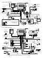
8. 'GN5' WIRING DIAGRAM
Aerial
System unit
Ultrasonic
sensor US2
Ultragarsinis jutiklis
Contacts of
relay K1
Engine bonnet
switch
Imax=7 A
Right direction
indicators
Imax=7 A
Left direction
indicators
Imax=2 A
12
1
3
Cut-off
Imax=130mA
1
4
+
5A
86
4
+12 V
+
30
85
-
87
87a
86
'Ground'
6
Vehicle battery
ACC
87
ON
87a
+12V
30
86
Use when the switch in the door
strut or the luggage compartment
switch commutates +12V
(e.g. in BMW vehicle)
85
30
87a
Engine ignition
switch
3A
Switch in the
door strut
87
5
3
86
or
7
85
Connect to link
2
15A
Unlocking pulse
0,5s/4s 130mA
Recomended
1N4004
-
+12V
for indci ators
15A
3
+12V
+12V
+12V for system
6
3A
85
30
87
87a
Cut-off circuit
2
System LED
-
Siren
5
2
Luggage compartment
or secret switch
+
-
123456
Grey
Yellow
Orange
Black
Yellow
Red
1234567
Black
Yellow
Blue
Grey
Brown
White
Red
Sensor signal '-'
'Ground'
+12 V
Switch in the
door strut
-
12 3
START
Central lock
motor
Locking pulse
0,5s/4s 130mA
9. 'GN6' WIRING DIAGRAM
Aerial
System unit
GSM
aerial
Two-level strike
tilt sensor
KSD
Sensor controled by
programator MBPR
(see documentation)
GSW
Contacts of
relay K1
Relay contact
K1
K2
12345 123 12
2
+12 V
7à
Right direction
indicators
Imax=7 A
5
2
3
4
86
87a
87
Central lock
motor
85
30
Unlock pulse
0,5s/4s 130mA
-
+
Lock pulse
0,5s/4s 130mA
3A
86
87a
6
85
30
Fuel pump
cut-off circuit
87
START
86
+12V for indicators
'Ground'
3
+
85
Vehicle battery
Siren/speaker
1
+12V
VK
-
Imax=130mA
3A
Imax=130mA
30
15A
Imax=7 A
+12V for system
5
ACC
87
6
15A
ON
87
87aa
System LED
86
87a
87
30
85
4
Engine ignition switch
Left direction
indicators
+12V
5A
+12V
Blue
GND
10
-
Blue
White
Pink
Brown
Black
Orange
Grey
Red
Green
Blue
Yellow
+12V
1
Orange
1 2 3 4 5 6 7 8 9 10 11 12 13
123456
Green
Green
Orange
1 2 3 4 5 6 7 8 9 10
Red
Black
Grey
12 3
'Sensor signal'/'Warning'
'Ground'
+12 V
Grey
Yellow
Orange
Black
Yellow
Red
Switch in the door strut,
luggage compartment or
engine bonnet
3A
8
Imax=2 A
5A
+
+12V
9
+12V
*Note: 1. 7à wire can be connected to the ground or to the 10 wire.
2. If 9 is conencted with a secret button, engine bonnet sensor must be connected to the
1
wire.
Engine bonnet switch
or secret button