1
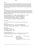
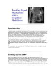
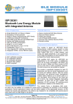
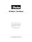
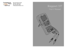
MICRO THERMO TECHNOLOGIES™ DT-EEPR Troubleshooting Guide Document No.74-MTA-1004-R1.1 No part of this publication may be reproduced, stored in a retrieval system, or transmitted, in any form or by any means, electronic, mechanical, photocopying, recording, or otherwise, without the prior written permission of Micro Thermo Technologies. © 1997-2015 by Micro Thermo Technologies. All rights reserved worldwide. Local Phone: (450) 668-3033 | Fax: (450)668-2695 Toll Free Canada: 1-888-664-1406 | Toll Free USA: 1-888-920-6284 www.sporlanonline.com/micro-thermo TABLE OF CONTENTS 1. INTRODUCTION .................................................................................................................... 1 1.1 USING THIS DOCUMENT ............................................................................................................... 1 1.2 PREREQUISITES .......................................................................................................................... 1 1.3 ADDITIONAL DOCUMENTATION .................................................................................................... 1 1.4 CONVENTIONS USED IN THIS MANUAL ........................................................................................... 1 2. GENERAL CONSIDERATIONS ................................................................................................. 1 3. CHECKING THE BOARD’S POWER SUPPLIES .......................................................................... 1 4. TESTING AN EEPR VALVE AND ITS WIRING ........................................................................... 2 4.1 DESCRIPTION OF EEPR VALVES .................................................................................................... 2 4.2 CHECKING THE CONNECTIONS ...................................................................................................... 3 4.3 CHECKING THE VALVE’S COILS AND WIRING .................................................................................... 3 5. CHECKING A PARTICULAR MOTOR DRIVE ............................................................................. 4 6. REPLACING A VALVE AND OTHER REPAIRS ........................................................................... 5 7. MISCELLANEOUS .................................................................................................................. 7 7.1 FUSE ........................................................................................................................................ 7 7.2 FLASH MEMORY ........................................................................................................................ 7 REVISIONS HISTORY ................................................................................................................. 8 74-MTA-1004-R1.1 DT-EEPR Troubleshooting Guide.doc i 1. Introduction 1.1 Using this document This manual addresses the trouble-shooting of DT-EEPR (Dual-Temperature Electric Evaporator Pressure Regulator) Controllers. The Micro Thermo part number of the DT-EEPR Controller is 950-636C. The 6-valve DT-EEPR Controller is supported in Alliance v. 5.1 or later. The following versions are current as of this writing : Hardware : P/N 950-636C R32 Alliance and plug-in : version 5.2 Neuron firmware : version 2.15 PIC firmware : version 1.11. 1.2 Prerequisites It is assumed that the reader is familiar with electrical measurements and the use of a multimeter. Prerequisites include knowledge of refrigeration practices in supermarkets and experience with the basic tools of the MT Alliance system. It is assumed that the user is familiar with the MT Alliance software (menus, views, toolbars, etc.) and with Micro Thermo plug-ins. 1.3 Additional Documentation Using the DT-EEPR Controller in Alliance is covered in : MT Alliance DT-EEPR Quick Set Up Guide (PUID 72-MTA-1025) and in MT Alliance DT-EEPR User Manual (PUID 73-MTA-1003). Basic skills of using Alliance are covered in : MT Alliance User Manual (PUID 75-MTA-1005) 1.4 Conventions Used in this Manual For your convenience, several screen captures are included, to describe the procedures. Certain images also contain numbered balloons referring to the numbers indicated in the corresponding procedure. Lastly, some terms are in bold to emphasize important points. 2. General Considerations All measurements should be performed with a floating instrument (such as a battery operated multimeter). Avoid connecting the board’s “Gnd” test points to Earth Ground. Depending on the existing connections, connecting a grounded oscilloscope probe to the board may cause a short circuit and interfere with normal operation. 3. Checking the Board’s Power Supplies The board layout drawing on top of next page shows the location of the test points. This drawing also appears in the Board Layout Page of the plug-in. 74-MTA-1004-R1.1 DT-EEPR Troubleshooting Guide.doc 1 +5V RESET B TX NETWORK EARTH RX SERVICE VALVE 1 20 21 Factory Flash 6 Factory VALVE 2 VALVE 3 VALVE 4 SA 2 NEURON/ NETWORK 4 AREA EARTH 24V AC1 AC2 POWER IN VBus PicBus 2.5V 1a MOTOR DRIVERS PS BR+ DC Gnd Gnd +5V ECLK POWER SUPPLY AREA VALVE 6 7 DC FUSE VALVE 5 Hand 1b held Factory EEBlank S p o r la n R G W B 5 Gnd Gnd Gnd 3 Stabil Gnd (PIC PROGRAMMING) A PICS 1,8V The AC voltage between the two terminals of the power input connector (1a) should be in the range of 19V to 30V. The 5V green indicator (1b) should light up when power is applied. The following measurements are done with the multimeter set to Volts DC, with its Common terminal connected to anyone of the 3 “Gnd” test points. The 5V test point (2) normally lies between 4.9V and 5.1V. The 1,80V reference (3) should lie between 1.78V and 1.82V. The 2,50V reference (4) should lie between 2.47V and 2.53V. The “DC” test point (5) is the unregulated supply. It is around 10V when all the valves are idle, gets up to 16.4V when driving a cold valve, 18.5V when driving a room temperature valve and may reach up to 20.6V for a hot valve or a valve with very long cables (larger resistance). 4. Testing an EEPR Valve and its Wiring This section describes the valve related malfunctions that are most likely to occur on a site, and their symptoms. 4.1 Description of EEPR Valves All the valves supported by the DT-EEPR Controller use bipolar stepping motors. The Controller keeps track of the mechanical position of the valve by counting the number of steps. The valve is initialized when the controller is reset, and at least once a day thereafter. Initialization consists of closing the valve for a large number of steps, then starting to count steps from zero. Bipolar stepping motors have a pair of coils. The two coils are insulated from each other. Sporlan valves of the CDS series and the SDR-4 use a gearbox and have a total of 6386 steps. The motors of the Alco ESR-12 and ESR-20 valves drive the screw directly and have 800 steps. All these valves are of a balanced port design. The balanced port reduces, but doesn’t completely eliminate, the effect of differential pressure on valve positioning. 74-MTA-1004-R1.1 DT-EEPR Troubleshooting Guide.doc 2 1 The SDR-3 is a smaller valve suitable for individual Dual-Temp cases. It is different from all other Sporlan valves on three counts : it has 3193 steps, it is not compensated for pressure differentials and it must be installed so that the flow tends to close the valve (following the arrow printed on the valve itself.) For Sporlan valves, one coil corresponds to the Red and Green wires, the second coil being White-Black. Color coding is the same for Alco valves, except that Blue is used instead of Green. Be aware that switching one of the wire pairs (Red with Green, for instance) will cause a valve to open when it should close, and vice versa. 4.2 Checking the Connections Check the colors of the valve’s 4 wires. Pull on the wires to make sure that no connection is loose. The 4 color-coded wires of a Sporlan valve should be connected in the sequence Red-Green-White-Black, as indicated by “R-G-W-B” in the figure, on top of the preceding page. For an Alco Valve, wire colors are the same except that Blue replaces Green. A loose connection may cause a valve to get uninstalled, since the controller constantly checks for the presence of the coils. This may cause the %Open Trendgraph to rise momentarily to 163.83%, as the valve’s position becomes unknown during the initialization procedure that follows an automatic reconnection. Since the valve motors are inductive, an intermittent connection causes sparks that disturb the PIC (Programmable Industrial Controller) that drives it. The PIC then undergoes a reset and could even become damaged. If there is any evidence of a valve getting uninstalled, it is strongly recommended to replace its connector. 4.3 Checking the Valve’s Coils and Wiring The cables used to connect the valve to the controller’s output connector are not critical, because the valves are current driven. AWG18 cables can drive a Sporlan valve to 500 ft or an Alco valve to 200 ft. Increasing the size of the wiring will not yield an appreciable gain. The valve being plugged into one of the Controller’s output connectors, check that its indicator (7) lights up. If it remains Off, the drive is probably powered Off. It can be powered On again, using the Power On button in the Current Values window of the plug-in, as shown on Page 6. This green LED (6) blinks to show that the drive is searching for a valve. It flashes 50% On, 50% Off when the valve is moving, and it remains lit when the valve is installed but idle. The controller will not install a valve unless the resistance of its two coils falls within the normal range for the Valve Series declared in the System Page of the plug-in. If the board is not yet configured, the controller will try to install both Sporlan and 12V Alco valves. The range of resistances that the Controller allows is indicated in the table on the next page. 74-MTA-1004-R1.1 DT-EEPR Troubleshooting Guide.doc 3 Valve series Minimum Nominal Maximum Sporlan CDS 57 Ω 75 Ω 103 Ω Alco ESR 12 volt 23 Ω 30 Ω 42 Ω To test the coils reliably, the valve has to be physically disconnected from the controller. Although a valve can be unplugged at any time, it is recommended to power off the drive first. This is done by clicking on the Power Off button in the Current Values window of the PlugIn, as described on Page 6. If you intend to check all the valves, consider powering Off the whole board, so that you won’t need to go back to the plug-in to power On all the valves again. The Power In connector (1A) can be unplugged at any time. The valves will keep their respective positions. They will be initialized automatically when the board is powered back On. Red Green/ Blue White 8 Black 1234 Disconnected valve connector Measure the resistance of both coils, using a multimeter (8). The figure illustrates the procedure for the Red-Green coil. The measurement yields the sum of the resistance of the coil and its wiring. The range of acceptable values is given in the table above. The lower resistance values apply to a very cold valve, and the higher values are for a very hot valve. An Alco valve can be disconnected at the valve itself, and the resistance can be measured at the exposed pins directly. This makes it possible to discriminate between an open coil and defective wiring. The pinout of an Alco valve is shown in the figure. Using the multimeter, check that the two coils are insulated from each other and from earth ground. An infinite resistance should be obtained, for these 3 measurements. Even if the two coils have a normal resistance, the drive will not work if they are not insulated. A short circuit of one of the wires to ground is the most likely trouble, which is worth ruling out. 5. Checking a Particular Motor Drive When performing the tests described below, please remember that the Controller moves one valve at a time. This feature makes it possible to run the board with less power, which is adequate for normal valve operation during refrigeration and defrost. – When an output is not connected, the valve LED (7) blinks every 2 seconds, unless it has been powered OFF using the Plug-In (see Page 6.) 74-MTA-1004-R1.1 DT-EEPR Troubleshooting Guide.doc 4 If you need to check the system and no valves are available, two resistors can be used to simulate a valve. This can’t be done with the 5-valve MT-EEPR board, which needs to see an inductance, instead of a resistance. Two 75 ohm, 2-watt resistors simulate a Sporlan valve, as illustrated. Two 27 ohm or 33 ohm 3-watt resistors can be used to simulate an Alco valve. Connect the valve (or the pair of resistors) to any one of the 6 controller’s outputs (6). – The LED flashes 50% ON, 50% OFF during initialization. This lasts for about 45 seconds for a Sporlan valve and 15 seconds for an Alco valve. – The AC voltage between the Red and Green terminals (Red and Blue for Alco) or between the White and Black terminals is about 10V while the LED is flashing. – Measure the idle voltage while the valve’s LED remains ON steady. The DC voltage is then approximately ±3 volts, for a Sporlan valve, and ±2 volts for an Alco. Polarity depends on the step number that the drive is holding. The exact idle voltage depends on the valve’s resistance, since it is current driven. Holding current is ±40mA for a Sporlan valve and ±60mA for an Alco Valve. To calculate the exact idle voltage, simply multiply the measured coil resistance by the holding current. If, for example, a coil of a Sporlan valve measures 68 ohms, you should expect about ±2.7 volts DC, since 68 40mA 2.72V A controller with the red “Factory” LED lit (see the board drawing on Page 2) will detect both Sporlan and Alco 12-volt valves. If the “Factory” LED is OFF, the controller is probably configured, and it will detect only valves of the selected Valve Series. 6. Replacing a Valve and Other Repairs A valve that has an open coil will not be detected. The yellow dot (11) in the Valve Config page will turn grey and the Plug-In will show “No Valve” (16) in the Process page. A stuck valve will still be detected, yet give incorrect readings of %Open. The temperature control will not function properly, but actual pressure measurements may be needed to prove that the valve is not moving as 11 it should. Although very unlikely, a valve may get stuck as a result of mechanical failure. It is more likely to happen after defrost. Sometimes, it’s possible to get it to move again by initializing it. 74-MTA-1004-R1.1 DT-EEPR Troubleshooting Guide.doc 5 Manual Initialization is done as follows : – Click on the Current Values button at the bottom of the main DT-EEPR plug-in window, to open the Current Values window. – Select the valve (12). 12 – Click on the Initialize button (13). A valve which gets stuck usually remains marginal, and should be replaced. Before unplugging a valve on a live controller, it is preferable to power Off the drive. 13 15 14 The procedure to power Off a drive is as follows : – Select the valve (12) in the Current Values window. – Click on the Power Off button (14). The Power Off button becomes greyed, to confirm that the command has been given. After several seconds, the green rectangle (15) becomes grey, to confirm that the command has been executed by the node. The Power Off button is then replaced by a Power On button. After the valve is replaced, the drive will need to be powered back On. Powering On a drive is done as follows : – Select the valve (12) in the Current Values window. – Click on the Power On button (14). What happens depends on whether or not a valve is present. 74-MTA-1004-R1.1 DT-EEPR Troubleshooting Guide.doc 6 – If a valve is detected, it gets installed and initialized. The Initialize button, which was greyed when the drive was powered Off, becomes active after initialization is completed. A valid value of %Open appears at the bottom of the Valve Control Page, in the Process Page and in the Current Values Window. The Valve Indicator (7) on the board shows this activity. – If no valve is detected, the banner in the Process Page changes from “Power Off” to “No Valve” (16). The Valve Indicator (7) blinks to indicate that the drive searches for a valve. If, as a result of a breakdown, the refrigeration system has been unable to maintain the set temperature for some time, large temperature errors have accumulated. To flush the errors accumulated during the malfunction, follow these steps : In the Process Tab, click on the “More/Less” button (17) to see the details, if needed. Click on the Reset Button (18) of the Accumulated Errors. After a few seconds, the command is executed and the Integral Error (19) drops to 0.00. The Long Term Error is also reset. It isn’t shown in the Process Page, but the Long Term PID Correction also becomes equal to 1 (0 error), in the Current Values Window. 16 18 19 17 7. Miscellaneous 7.1 Fuse The DT-EEPR Controller requires a 4 ampere fuse. A 3 ampere fuse is adequate for Sporlan valves, but it is recommended that a 4 ampere fuse be installed in all cases. 7.2 Flash Memory If : – the power supply voltages are normal, but there seems to be no activity on the board, – in particular, if the TX LED (20) doesn’t flash, even when you push the Service Pin, you could try pushing down firmly the Flash Memory chip. This Flash Memory IC is located on the left-hand side of the board, as shown in the board’s layout on Page 2. It is the only socketed IC of the DT-EEPR board. Pushing it down may fix a bad contact of a pin with the socket. Then, reset the node (21). 74-MTA-1004-R1.1 DT-EEPR Troubleshooting Guide.doc 7 Revisions History REV Revised by Date Document Creation CB 08-Dec-06 0.2 Comments CC 25-Jan-07 0.3 Revision CB 01-Feb-07 1.0 Revision PUID change from 74-PHW-1004 1.1 Cover page and formatting 0.1 Description 74-MTA-1004-R1.1 DT-EEPR Troubleshooting Guide.doc CB/RL 19-Apr-07 ER 30-MAR-2015 8