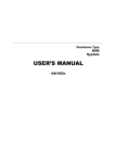
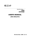
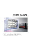
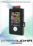
1
Stand Alone Type
DVR
SYSTEM
USER’S MANUAL
8/16CH
(Server)
• INDEX
• CHAPTER 1. Specification & System organization
1. Product Contents List -------------------------------------------------------- 3
2. System Organization --------------------------------------------------------- 4
• CHAPTER 2. Description
1. Front Panel --------------------------------------------------------------- 5
2. Rear Panel --------------------------------------------------------------- 7
3. Remote Controller ---------------------------------------------------------- 8
• CHAPTER 3. Display
1. System Power ON ---------------------------------------------------------- 9
2. Screen View Selection ------------------------------------------------------ 10
3.Display Mode ------------------------------------------------ 10
4. PTZ/FOCUS Control -------------------------------------------------------- 11
5. System Power OFF --------------------------------------------------------- 11
• CHAPTER 4. Search
⊙ Go to Search Mode --------------------------------------------------------- 12
1. Search by Date/Time ------------------------------------------------------- 12
2. Search by Event ----------------------------------------------------------- 13
1
• INDEX
• CHAPTER 5. SETUP
⊙ Go to Menu -------------------------------------------------------------- 14
⊙ Go to System Setup -------------------------------------------------------- 14
1. Display ------------------------------------------------------------------ 15
2. Camera ----------------------------------------------------------------- 19
3. Sound ------------------------------------------------------------------ 22
4. System ------------------------------------------------------------------ 23
5. Event/Sensor ------------------------------------------------------------- 28
6. Disk Management ---------------------------------------------------------- 31
⊙ Go to Record Menu -------------------------------------------------------- 32
1. Recording Operation -------------------------------------------------------- 32
2.Timer/motion setu p ------------------------------- --------------- 33
3. Alarm Record Schedule ----------------------------------------------------- 34
4. Panic setup ------------------------------------------------------- 34
⊙ Go to Archiving ----------------------------------------------------------- 36
1. CD-RW and USB Back up --------------------------------------------------- 36
2
1. Specification & Organization
1. Product contents List
Please Confirm the Contents When open Package.
① Basic Contents
Power Cable
User’s Manual
Remote Controller
Remote Client
Program Install CD
AAA Battery X 2
② Option Contents
CD-RW
HDD
3
USB MOMORY
1. Specification & Organization
2. System Organization
Alarm Sensor #1-8(16)
Camera #1-8(16)
Remote Client PC
Relay Out
Image Printer
Alarm Input/Out
NETWORK
AVI Backup
TCP/IP
Video In
WEB Client
Video Out
Backup
Remote
Controller
USB
VCR
VGA
Monitor
CD-RW
AV Monitor
4
2. Description
1. Front Panel
2
3
4
8
9
10
1
5
6
7
11
1
POWER : System Power On/Off
2
CD/DVD RW : Back up image to CD/DVD RW
3
Channel Select button : Select Channel or Input Password.
4
Function button : Function button as Shortcut button for convenience.
5
Focus : Set up focus / Playing back, Fast backward.
6
PAUSE : Pause playing
7
IRIS : Setup Iris / Playing, Fast forward.
8
Direction Control Button : Control direction , Enter, Control menu and searching recording
9
HOLD : Hold Jog dial.
10
JOG dial
11
ESC : Cancel Setup or Return Previous Mode.
Tip
• Channel Selection Button is Prior to DISPLAY.
• When Remote Controller Sensor Input is Blocked by Something, it Cause
Remote Controller do NOT Work Properly.
• When Press any Button, it Operate with Beep Sound.
5
1
2. Description
* Shortcut button
①
③
②
Display
SEQ
MENU
Ptz/Focus
Search
Zoom
⑤
④
⑥
1
DISPLAY : Select Screen Division Mode or Rotation Mode.
2
SEQ : Select sequence screen mode.
3
Menu : Go to System Setup Menu
4
PTZ/Focus : Go to Camera PTZ Control .
5
Search : Go to Search Mode for Searching Recorded Data
6
Zoom : zoom in.
* FOCUS / IRIS button
FOCUS
1
IRIS
2
1
NEAR : Set camera focus nearly.
2
FAR : Set camera focus far.
3
CLOSE : Close camera iris.
4
OPEN : Open camera iris.
3
6
4
2. Description
2. Rear Panel
4
1
5
2
6
7
11
8
1
Video IN / Loop : Input & Output of video
2
Monitor out : Output DVR Video to AV Monitor.
3
9
10
12
SVHS : Output Video by Connected SVHS.
3
Spot #1 ~ #4 : Output Spot-out Video to AV Monitor.
4
Audio In : Audio Input Terminal Related with Camera.
5
Audio Out : Output Audio Data.
6
Alarm : Connect Port for Sensor
7
Relay : Connect Port for Relay
8
USB : USB port for use the USB memory stick and USB HDD Backup.
9
VGA OUT : Output Video to a Computer Monitor by Connected VGA
10
RS-232C : Connect Port for Program Debug.
11
RS-485 : Connect Port for PTZ
12
Ethernet (TCP/IP) : Port for Cross cable. (Possible to Remote Surveillance.)
13
POWER : Power Cable connection.
Tip
• When System Installation, Please Install under System Power Off Status.
• Please Use Specific Adaptor when Power Supply.
7
13
2. Description
3. Remote Controller
POWER
MENU: Open Menu
System
ON/OFF
Channel Selection Button
(16ch Available, #1~4 Button)
RETURN
ENTER: Apply Setup Change
Cancel Setup
or Return to
Previous
Search Controller : Control Playback Option,
Menu Movement, PTZ/Focus Control
Change
Screen Mode
Open
Search Mode
PTZ/IRIS Mode
• Unused Button’s Description is Omitted.
• Every Button is Operated Same as Front Panel Button.
• Remote Controller can Operate when Remote Controller Sensor Input Part Reacted Each Other.
※ If there are many DVR at the same place, they are reacted together when press remote controller.
8
3. Display
1. System Power ON
• Press power button to start system.
• After Checking Hard Disk, display mode is shown.1
• Initial Screen View Mode is Quad Division Mode and
Recording Mode.
<Picture of Power On after Finishing Installation>
CAMERA
• Each Channel Indicate Camera Name & Recording Status.
• Present Time & Date Indicate at Monitor Central Lower Side.
2005/01/01
00:00:00
Tip
• Check System Condition at LED
POWER : Showing System On/Off
RECORD : Showing Record On/Off
NETWORK : Showing Client Connection Status
9
3. Display
When connect by the Remote Agent or Web Client ,
Indicator appear.
• Indicate the network condition.
- Green: Network is stable.
- Blue: Network is unstable.
- Red: Network is very unstable.
2. Screen View Selection
• Select One Channel among 8/16 Channels.
• Move to One Enlargement Watch Mode when Quad Screen Division Mode.
• Move to One Enlargement Watch Mode when Rotation Mode.
3. DISPLAY MODE
• User can Select various Watch Mode.
• Quad (8/16CH) Watch Mode is Initial Mode when System Start.
10
3. Display
4. PTZ/FOCUS Control
• Control Camera PTZ (Pan/Tilt/Zoom).
• Press PTZ Button to Open PTZ Menu.
• Each icon mean the button of front keyboard.
• Press PTZ button one more time, then another menu appear.
• Control each function by front keyboard.
• F: Focus
I: IRIS
5. System Power Off
• Press Power Button to System Off.
• Input Password and Press Enter to Shutdown System.
Tip
• System Log-On Possible ID : ‘Administrator’, ‘Manager’, ‘User’
Administrator: All Function Access.(System On, Shutdown, Setup, Search)
Manager: System On and Search.
User: Only System On.
11
4. Search
⊙ Go to Search Mode
• Press Search Button and Log-In.
(Administrator or Manager )
• Use Direction Key to Move Menu.
• To Open Each Menu Press Enter.
• Press Return button to Move to Previous Menu or
Exit Search Mode and Return to Watch Mode.
1. Search by Time
- Possible to Search Recorded Date/Time.
① Move Cursor to Selected Date in Calendar.
(Date of record data is shown green color.)
② Press Enter to Open Selected Date.
③ Recorded Time Appear to Upper Side.
④ Press Enter at Selected Time.
(One Scale is 15 Minutes)
⑤ Menu Disappear and Output Recorded Video.
• Showing Recorded Date & Time at under Side
1 as Watch Mode.
1 Showing Playing Condition at Right-Under Side.
• Channel Selection Button in Watch Mode & DISPLAY
1 Button are Apply the Same as Search Mode.
(But Menu, Search, and PTZ Buttons are Exception)
12
2004/01/01
00:00:00
>
4. Search
• Control Playing Video
①
: Basic Playing Mode (Normal Speed (1X) Forward Playing)
②
: Normal Speed Backward Playing
③
: Pause Video
④
: Fast Forward (2 ~ 64 Speed)
⑤
: Fast Backward (2 ~ 64 Speed)
⑥
: Same Function as # ④,⑤
※ Press Normal Forward/Backward Button in Pause, Move to Next/Previous Frame.
2. Search by Event
- Searching Video with Event Occurrence to Set up Period.
Set up Period to Select Start Date & Finish Date
for Searching Event.
Alarm : Searching Alarm Event during the Selected
1
Period.
Motion : Searching Motion Detected Event during
1
the Selected period .
Timer : Searching Schedule Change or Recording
1
Setup Change Event.
System : Searching Power On/Off Event (etc.)
1
Concerned System Event.
Event List Showing at Below Output Window
Channel: Choose the channel for searching.
Tip
• Alarm, Motion, System can be Select plural by Check (V) (by Pressing
ENTER button).
• To Change Setup, Press Enter and Press Direction Key
After Changing Setup, Press Enter to Exit.
13
5. Setup
⊙ Go to setup
① Press SETUP Button.
② Ask Password.
③ Input Password Using by Channel Select Button.
④ After Input Password Press Enter to See Menu.
• Initial Administrator, Manager, User Password is 1234.
Tip
• Showing Password as *
• Changing Password (System setup->System -> User management ).
: To erase initial password, Press fast backward button.
• Only Watch Mode can go to Entering setup.
(Search & PTZ/Focus Mode can’t move to Menu)
⊙ Go to System setup
• Choose the “system setup”.
14
5. Setup
1.Display
- Video Setup for Watch Mode
• Every System Setup can Change or Maintain at Menu (6 Setup).
•
Move to Menu Using by Up & Down Button.
•
ENTER
To Open Detail Menu, press “the Enter”.
ESC
Return to Previous Menu or Return to Watch Mode.
•
1-1. OSD
Tip
• When finishing that change the setup data,
Press the
• Status Bar : Record Condition Mark On/Off. (Recording: Red, Pre-recording : Green)
• Camera Title: Setup Camera Name to Show Left-Upper Side.
• Event Icon: Indicate the menu location by icon.
• Border : Border Mark On/Off when 4CH Division Watch Mode.
• Border Color : Select Border Color. (White, Blue, Red, Yellow, Green, Gray)
• Menu transparency : Setup menu transparency.
• Motion Sensor : Setup display motion sensor.
- Active : Display motion sensor of motion detection area.
- Inactive : Display motion sensor except motion detection area.
- Off : No display of motion sensor.
• Motion sensor color : Setup motion sensor color.
• Motion transparency : Setup motion transparency.
15
certainly.
5. Setup
1-2. MONITOR
• Sequence dwell : Setup rotation cycle time(1~60 sec.) When rotation mode at watch mode.
• Spot-out dwell : Setup spot-out time cycle(1~60 sec.) to transmit video.
• De-interlace mode : Remove screen spread on high.
Resolution , low frame ※Only applying when D1(704X480)
• Alarm pop-up mode: When alarm happen, alarm happened channel pop-up.
• Alarm pop-up dwell: Alarm pop-up time(1~60sec.)
• Motion pop-up mode : When motion detected, motion detected channel pop-up.
• Motion pop-up dwell : Motion pop-up time(1~60sec.)
• Display mode : Select display mode. (VGA/AV)
16
5. Setup
1-3. SEQUENCE
•
•
•
•
•
• Activation : Setup activation on/off.
Only one list can be activated.
• List : Sequence title.
• Press enter at list and edit setting.
Choose add to add sequence.
Total 16set of sequence can be made.
Input sequence title by virtual keyboard.
Choose activation on/off.
Press ‘SAVE’ to move to setup sequence.
* Setup sequence
① Press enter then red border line
disappear. Setup mode activated.
④ Setup next mode as before.
Total 16 mode can be selected.
② Select display mode among 16
③ Display mode selected, press
mode. 1set can be made by 16 mode. channel selection button as you
want. Input all channel NO.
⑤ When finish setup, press return.
(Save & Exit / Exit / Cancel)
17
⑥ By SEQ button of front panel,
can see setup mode.
5. Setup
1-4. SPOT OUT
• Channel : Select spot out channel(1~4).
• Select channel from the list by V check. (#1~#16)
• User can see the selected channel on spot out channel.
18
5. Setup
2.Camera
- Setup Camera
2-1. Camera Title
• Covert : Setup Covert On/Off
*What’s Covert?
When Covert On Watch Mode, Video Display is Hidden, but Recording is On.
• Title : Setup Camera Name by Virtual keyboard.
• Input the title by “Enter” after choose by direction key.
2-2. Color Setup
• Enter to control mode by press ENTER button.
• Control the Monitor Bright, Contrast, Color, Tint.
• All Setup Possible to Control 0~100.
• Setup Channel by Channel.
19
5. Setup
Tip
※ How to use the Virtual Keyboard
• Input the title by “Enter” after choose by direction key.
• Press the
button for shift then choose the other characters.
• Erase characters by
• Press
button.
for finish.
2-3. PTZ Setup
• Address : Select PTZ Camera Address.
• PTZ Protocol : Select Kind of PTZ Camera.
• Baud Rate : Setup PTZ Communication Speed.
(2400, 4800, 9600,19200, 38400 BPS)
• Enter
button and setup the detailed PTZ.
※PTZ Supplied Protocol : Samsung(MRX-1000), Samsung(SCC641),Honeywell(SD1)
Honeywell((GMC),Lilin(Fastdome), Fastrax(Ⅱ), GC(655N),
D-MAX, Sunin DSC-230, Scan Dome-Ⅱ, Vicon,Philips8560-700
Sensormatic,Panasonic(WV-CS850), Panasonic(WV-CSR604),VRX-2101
Kalatel(KTD-312), PELCO-D, PELCO-P,Dynacolor(D7722)
20
5. Setup
2-4. Motion Sensor
• Press AREA SETUP button.
• Choose the Partial Motion Region channel by
channel.
• Sensitivity: Control sensitivity.(1~10)
• Move Cursor by Direction Key and Press Enter for
Region select.
• Select region and press Enter one more time.
• For finish area setup, press Return.
• Press return, then next menu show up.
• Select All : Select Entire Region.
• Deselect All : Cancel Region Setup.
• Cancel : Cancel Change Setup & Exit.
• Save & Exit : Save the Changes & Exit.
21
5. Setup
3. Sound
3-1. Audio
- Audio Setup.
• Live Audio : Audio Output ON/OFF.
Live Audio Output from Audio In Terminal.
• Audio Monitoring Channel: Select Channel for Audio Output.
• Network Audio TX: Choose the Audio transmission.
• Network Audio RX: Choose the Audio receive.
3-2. Buzzer
- Buzzer Setup
• Keypad : Keypad buzzer On/Off.
• Remocon : Remocon buzzer On/Off.
22
5. Setup
4. System
- Basic Environment Setup
4-1. date/time
※ First of all, Timezone should be setup as your location.
• Date TIME: Setup Present Date time.
(If Time Setup to Past Date, Ask Delete Data for the Past Date.
(NO->Date/Time No Change, YES->After Delete Past Data and Change Date/Time )
• Date Format : Select Date Output Type. (Ex: 2005-00-00, 2005/00/00)
• Time Format : Setup Time Type as 12 Hour Base or 24 Hour Base.
• Network Time Server setup : Setup Present Time by Time Server. (Default is time.nist.gov)
• D.S.T: Daylight Saving Function On/Off.
• Time Zone Setup : Choose the time by GMT standard.
Tip
※ How to Time setup
1. Setup Timezone as your location.
2. Setup the Network Time server and press the “Sync” button.
3. If can not get correct time automatically, setup the date/time manually.
4. If don’t follow as upper, you may have the time error and the recording data search error.
23
5. Setup
4-2. Network
• IP Address : Input IP Address.
• Gateway : Input Gateway IP for Internet Server.
• Subnet Mask : Input Subnet Mask IP.
• DNS Server: Input DNS Server IP.
• DDNS Server: Input DDNS Server IP.
• Net Client Port : Input net client port.
• Web Server Port : Input web server port.
• Max TX Speed : Setup Max TX Speed.
※ If Change Network Setup, New Change Apply
when after Rebooting.
• DHCP (Dynamic Host Configuration Protocol) : Indicate IP Address for the DVR Automatically.
1.
2.
3.
4.
5.
Enter to ‘System -> Network’ on the Menu.
Setup DHCP On/Off.
DHCP Off : User Input IP Address manually.
DHCP On : Indicate IP Address for the DVR Automatically. After DHCP On, Reboot the System.
Can see the setup IP automatically at the system information.
• DDNS (Dynamic DNS): You can connect the DVR by the fixed domain name(ex.00115f000001.dvrlink.net) at
client or Web without entering the IP address.
※ If you use the DDNS, there is no necessity to enter again the IP Address every connection.
1.
2.
3.
4.
5.
6.
Enter to ‘System -> Network' on the menu.
Setup DHCP On or Enter the IP address.
Setup DDNS ON and reboot.
Enter to ‘System -> System information’ on the menu.
Confirm the MAC address.
The domain name is "MAC address.dvrlink.net".
EX) If Mac Address is 00-11-5f-00-b5-a7, the domain name is "00115f00b5a7.dvrlink.net"
7. If you connect by "00115f00b5a7.dvrlink.net" at client program or Web, you can connect the DVR.
• Web Service
- On : Connect from Web browser enable.
- Off : Connect from Web browser disable.
Tip
※ 1. If your network connect at the router, please must port forwarding.
2. Please must enter the exact IP address, DNS Server, Gateway, Subnet Mask.
3. Please must connect the DVR at External Network.
If you don't follow 1,2,3 , you can't receive the DDNS service.
24
5. Setup
4-3. Mail
• Server: Setup the mail server by Virtual Keyboard.
• Port: Input mail server port by Virtual Keyboard.
• Security: Setup security On/Off.
Mail server needed certification, setup security on.
• User & Password: Input the DVR login user ID and Password.
25
5. Setup
4-4. User Management
User setup
• It is consisted 3 User Group as Administrator,
Manager, User.
• Total 7 user belong to 3 User Group can be made.
• Enter ADD button to make a new user.
• Input User ID, Password.
• Choose the Group.
• Input the E-mail Address.
• It can edit User ID information.
• E-mail notification On/Off : 1. ON:
2. OFF:
• Input the E-mail by Virtual Keyboard.
26
5. Setup
4-5. System Management
• F/W version: Server firmware version.
• H/W version : Hardware version.
• Video signal type: NTSC or PAL.
• Disk capacity: Used HDD capacity of the total HDD capacity.
• IP address: DVR’s IP address.
• MAC address: Fixed MAC address of the DVR.
• System name : Input system name by virtual keyboard.
• F/W update
- User can do F/W update by USB device.
- Press ‘PRESS’
- Select F/W from the list.
- Press ‘START’
• Factory default
- User can initialize all setup but recording data is not erased.
- Press ‘PRESS’ then warning message appear.
- Press ‘OK’, then all setup initialized.
• System data
- User can save/load settings.
- Press ‘SAVE’ to save current setup without message.
- Press ‘LOAD’ to load saved setup from USB device without message.
27
5. Setup
4-6. Control device
• System ID : Select system ID. (1~254)
• Protocol : Select protocol.
• Baud rate : Setup baud rate.
5. Event/Sensor
5-1. HDD Event
• Drive: HDD connected location.
• Smart alarm: Setup smart alarm on/off.
• Check interval: HDD checking interval.
28
5. Setup
5-2. Alarm Input
• Operation: Setup Alarm Sensor Connection Status.
(enable/disable)
• Type : Setup Alarm Sensor N/Open, N/Close Type.
• Normal Open : Open status in normal times, when
alarm out happen changed to close status .
• Normal Close : Close status in normal times, when
alarm out happen changed to open status .
• Page down/up : Move display page.
5-3. Alarm Output
※ Setup each channel when alarm, videoloss, motion happened.
• Channel : Select Channel.
• Mode: Setup Reacted Relay as Latched/Transparent Mode.
• Type: Setup Relay Type N/Open or N/Close.
• Operation: Setup Relay Connect with Alarm Sensor.
• Duration: Setup Reacted Relay Time. (5sec~5min or Until key-in)
• HDD Event: Alarm On/Off when HDD has the problem.
• Page down/up : Move display page.
Tip
• Latched/Transparent
Latched – When sensor alarm activated, relay reacted in setup duration.
Transparent – Relay reacted temporary during sensor alarm activate.
29
5. Setup
5-4. Buzzer out
• Operation: Setup Buzzer Enable/Disable.
• Mode: Setup Reacted Relay as Latched/Transparent Mode.
• HDD Event: Buzzer On/Off when HDD event is happened.
• Duration: Buzzer time(5sec~5min or Until key-in)
• Setup each channel when alarm, videoloss, motion are happened.
30
5. Setup
5-5. E-mail Notification
• Notification : Setup notification on/off.
- ON : If alarm, videoloss, motion and HDD event happened,
send the notification by the E-mail.
• Alarm, videoloss, motion can be selected. (Each channel)
6. Disk Management
• Record time limit : Setup record time limit.(12h~1month)
• Overwrite : Select Overwrite Permission when Hard Disk Full.
O N: Overwrite Hard Disk from Oldest Data.
OFF: When Hard Disk Full, Stop Recording and Buzzer Activated.
• Format : Refreshment Hard Disk. Press start button, then message of ‘All Recorded Data erased.’shown.
Select OK, all data deleted. Select NO, cancel format.
31
5. Setup
⊙ Go to Record Menu
• Choose “Record Menu”.
1. Recording Operations
• Schedule Mode: Choose the DAILY or WEEKLY.
• Pre-Event Recording Time : Setup Pre-Event recording Time.
(1~5 sec)
• Post-Event Recording Time: Setup Post-Event recording Time.
(1~5 sec)
• Pre-Event Recording : When alarm detected, record image including setting time before alarm happened.
• Post-Event Recording : When alarm detected, record image including setting time after alarm happened.
32
1
1
5. Setup
2. Timer/Motion Setup
2-1. Parameter
• Select parameter mode.
• Press “Enter” twice to setup, Move with right/left direction key.
• Press “Enter” to select area, and Press “Enter” for setup.
• Setup each channel. (Size, FPS, Quality, Audio)
• Setup each day when weekly mode.
2-2. Schedule
• Select schedule mode.
• Press “Enter” twice to setup, Move with right/left direction key.
• Press “Enter” to select area, and Press “Enter” for setup.
• Select mode among None/Timer/Motion.
Display : None-transparent, Timer-skyblue, Motion – Black dot.
• Setup each day when weekly mode.
33
5. Setup
3. Alarm Setup
3-1. Parameter
• Select parameter mode.
• Press “Enter” twice to setup, Move with right/left direction key.
• Press “Enter” to select area, and Press “Enter” for setup.
• Setup each channel. (Size, FPS, Quality, Audio)
• Setup each day when weekly mode.
3-2. Schedule
• Select schedule mode.
• Press “Enter” twice to select area . Move with right/left direction key.
• Press “Enter” to select area.
• Selected area is displayed with skyblue color.
• Setup each day when weekly mode.
34
5. Setup
4. Panic Setup
• To setup each channel, press enter.
• Setup each channel. (Size, FPS, Quality, Audio)
• By panic button of front panel, can record urgently as setup.
35
5. Setup
⊙ Go to Archiving
1. CD-RW and USB Back Up
• Device : Indicate CD-RW model and USB memory model automatically.
If you use the CD-RW and USB memory (or USB HDD) together,
it can choose the CD-RW and USB by direction key.
• From : Select start backup time.
• To : Select end backup time.
• Mode : Select backup mode. (Burning / Erasing & Burning)
• A/V channel : Select channel, video, audio for backup.
• Title : Change the title of backup by virtual keyboard.
• Event : Select attach event text file in backup.
• Start : Start Backup.
Tip
• Compatible CD Writer Models are LG(GCE-8526B,GCE-8527B),
SAMSUNG(SW-252F, TS-H292A, SH-522C),ASUS(CRW-5232AS),GIGABYTE(GO-R5232B)
• Compatible USB memory stick Models are LG(Royal,mobile,mirror), IMATION(iflash),Memorive PRO+
and Compatible USB HDD is CUTIE(FHD-254).
• Inside of Backup CD,USB Including Necessary Codec for Playback (IMM4 Install File).
• In case of RW Possible CD, Please Delete Previous Data on PC for Recording Again.
36
SUPPLEMENT
* HDD Installation
① Jumper Setup as Master or Slave
• Jumper Setup as master or Slave, Following the
` Direction of Surface of Hard Disk.
• Jumper Located at Hard Disk Data Cable or
1 Rear Side of Hard Disk.
• If One Hard Disk Installation, Setup as Master
If Two Hard Disk Installation, Second One Setup as Slave.
‼ When Hard Disk Add or Exchange, Must System Off
Properly (System Off by Power Button). If not, it’s a
Cause of Fatal Hard Disk Error.‼
※ Example of Samsung HDD Jumper Setup
• Refer to General Pin Setting in Jumper Pin Setting on HDD Surface.
• When One HDD Install, Setup Pin as Master and Connect Pin
1 at the Left End of Jumper.
• When Two HDD Install or Additional Install, First One Setup as
1 Master and the Other is for Slave. Slave Setup has No Pin.
• When More than Two HDD install, Setup as Master or Slave
1 to Connect One IDE Cable at the Same Method of Above.
!!Please Use Hard Disk which Possible to Supply Higher than
UDMA66.!!
② IDE Cable Connection to Main Board
• Confirm the IDE Cable Inside of Product
• Among the Three Connector, Indicated Blue Color
1 Connector Must be Connected with Main Board. Other
1 Connectors Connected with HDD
37