1
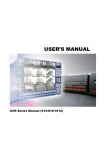
4-Channel Stand Alone
DVR
SYSTEM
DR4N
USER’S MANUAL
Revision Date : 11.08.2005
Firmware Version : V357_b1
Ex-Factory Date :
5/9/05
11/8/05
Important Product Safety Instructions
▶ Be sure to turn off the power before installation.
▶ Keep at least 8cm away from other machines or electronic products.
▶ Keep away from the direct rays of the sun or heater or similar devices. (may cause fire)
▶ Do not put metallic items such as cups, cosmetics, bottles, containers, etc. on this product.
(may cause fire or electric shock hazard)
▶ Do not block the ventilation holes of this product with any kind of metal or flammable materials.
(may cause fire or electric shock hazard)
▶ Do not put heavy objects on top of this product. (falling objects may cause injury)
▶ Fully insert power plug into electrical outlet. (loose connection may cause fire)
▶ Wipe gently with a dry cloth to clean the product. Do not use any chemical products or detergents.
(This may change the color of the product and/or harm the surface.)
▶ Immediately disconnect the power if a burning smell or smoke is emitted from the product.
▶ Do not touch the power plug & cable with a wet hand. (electronic shock hazard)
▶ Do not pull power plug out by force. (damaged power plug causes electronic shock hazard)
▶ Keep away from dusty or high humidity locations. These may cause malfunction of the product.
(Dust & other debris may cause fire and electronic shock hazard)
▶ Avoid dropping the product or subjecting the product to any heavy impacts.
▶ Keep this product away from strong magnetic fields or mechanical vibration. (it may cause malfunction)
▶ Do not install the product in extremely cold or hot locations.
▶ Do not open the cover of product without disconnecting the power and consulting with the manufacturer.
(fire and electronic shock hazard)
▶ Do not change the power supply without consulting with the manufacturer.
(It may cause malfunction and/or permanent damage)
▶ Use caution when installing BNC connectors and other cables to the I/O ports of this device.
The connectors and/or circuit boards could be broken or damaged by excessive weight on the cables.
▶ Contact the manufacturer’s technical support department when adding any devices to this product.
CBC America Corp.
Technical Service Division (TSD)
New York Office - 1 800 422 6707
Los Angeles Office - 1 800 888 0131
2
• INDEX
• CHAPTER 1.
Specifications & System organization
1. Specifications ------------------------------------------------------------- 4
2. Product Contents List -------------------------------------------------------- 6
3. System Organization --------------------------------------------------------- 7
• CHAPTER 2 . Physical Description
1. Front Panel --------------------------------------------------------------- 8
2. Rear Panel --------------------------------------------------------------- 10
3. IR Handheld Remote Controller ----------------------------------------------- 11
• CHAPTER 3. Installation
1. Hard Disk Installation ------------------------------------------------------- 12
2. CD-R/W & Hard Disk Installation ---------------------------------------------- 14
3. Camera Connection -------------------------------------------------------- 16
4. Monitor Connection -------------------------------------------------------- 16
5. Computer Connection ------------------------------------------------------- 16
6. Network Connection -------------------------------------------------------- 16
7. Alarm/Relay/PTZ Connection ------------------------------------------------- 17
8. Power Connection --------------------------------------------------------- 17
9. Finishing Installation -------------------------------------------------------- 18
※ Hard Disk Format ---------------------------------------------------------- 18
• CHAPTER 4. Display
1. System Power ON ---------------------------------------------------------- 19
2. Screen View Selection ------------------------------------------------------ 20
3. Screen Rotation Mode (SCR MODE) -------------------------------------------- 20
4. PTZ/FOCUS Control -------------------------------------------------------- 21
5. System Power OFF --------------------------------------------------------- 21
• CHAPTER 5. Search
⊙ Go to Search Mode --------------------------------------------------------- 22
1. Search by Date/Time ------------------------------------------------------- 22
2. Search by Event ----------------------------------------------------------- 23
• INDEX
• CHAPTER 6. MENU
⊙ Go to Menu -------------------------------------------------------------- 25
⊙ Go to System Setup -------------------------------------------------------- 25
1. Display ------------------------------------------------------------------ 26
2. Camera ----------------------------------------------------------------- 27
3. Audio ------------------------------------------------------------------- 30
4. System ------------------------------------------------------------------ 30
5. Event/Sensor ------------------------------------------------------------- 36
6. Disk Management ---------------------------------------------------------- 39
⊙ Go to Record Menu -------------------------------------------------------- 40
1. Recording Operation -------------------------------------------------------- 40
2. Continuous/Motion Record Schedule -------------------------------------------- 41
3. Alarm Record Schedule ----------------------------------------------------- 42
⊙ Go to Archiving ----------------------------------------------------------- 43
1. CD-RW and USB Back up --------------------------------------------------- 43
• CHAPTER 7. CLIENT
⊙ Remote Program Install ----------------------------------------------------- 44
1. Introduction to Client and Functions -------------------------------------------- 46
2. Settings ----------------------------------------------------------------- 47
3. Monitoring --------------------------------------------------------------- 54
4. Search ------------------------------------------------------------------ 58
5. Web Browser Client -------------------------------------------------------- 65
1. Specifications & System Organization
1. Specifications
Video Standard
PAL/NTSC
Audio
2-way Audio conference
Monitor Display
Real time: 30fps (NTSC) / 25fps (PAL) per camera
Covert Camera Operation
Programmable
Event/Log search
Up to 1,000,000 for user login, configuration changes, remote access,
connects and disconnects
Record Scheduling
Daily or Weekly; able to adjust recording on each channel, by the hour
Remote Access
TCP/IP, View, Search, Recording & PTZ Control by Client Software or Web
Playback
Single and Quad-Screen Playback
Pre/Post Alarm Recording
Up to 5 seconds (Pre), and up to 3 minutes (Post), adjustable per channel
VGA
For monitors with Multi-Sync Function only (1024 X 768 @ 60Hz)
Activity Detection
12 x 12 target grid; Sensitivity levels: 10
Simplex/Duplex/Triplex Operation
Triplex
Video Inputs
4 x 1Vp-p, CVBS, 75ohms, BNC, looping inputs
Monitor Outputs
1 x CVBS/S-VHS, VGA (optional)
Spot Output
1 x 1Vp-p, CVBS, 75ohms, BNC
Audio Inputs
4 x line-in, RCA sockets
Audio Output
1 x line-out, RCA socket
Resolution
352 x 240, 704 x 240, 704 x 480 (NTSC)
352 x 288, 704 x 288, 704 x 576 (PAL)
Compression Standard
MPEG-4
Recording Speed
352 x 240 @ 120fps (NTSC), 100fps (PAL)
704 x 240 @ 60fps (NTSC), 50fps (PAL)
704 x 480 @ 30fps (NTSC), 25fps (PAL)
Image Size
1-3 Kbyte (352 x 240, 352 x 288)
5-10 Kbyte (704 x 240, 704 x 288)
6-16 Kbyte (704 x 480, 704 x 576)
Backup File Formats
AVI, JPEG, BMP
4
1. Specifications & System Organization
OSD Languages
English, Spanish, Chinese, Dutch, Portuguese, French, Russian, Japanese,
Polish, Romanian, German
Ethernet Interface
10/100-Base-TX, RJ-45
Remote Function
Live View, Live Recording, Search, Setup, Back-up
Hard Disk Capacity
HDD x 3 (STANDARD DC SUPPLY USE)
HDD x 4 (OPTIONAL SMPS USE)
Secondary Storage Options
USB default (USB memory stick or USB HDD), CD-RW (optional)
PTZ Control
RS-485 serial interface
Network Speed Control
Bandwidth throttle, 8 levels
Alarm Inputs
4 x TTL, programmable as Normally Closed (NC) / Normally Open (NO)
Alarm Outputs
1 x Relay with NO/NC contact; 30VDC/1A, 125VAC/0.5A resistive
Pre-Alarm Recording
Up to 5 seconds, adjustable per channel
Supply Voltage
100VAC-240VAC, 1/0.5A, 60/50Hz
Power Consumption
Approximately 60 watts
Temperature Range
5℃ to 50℃
Recording Time Table with Various Speed/Resolution Settings
(for 160GB HDD)
___________________________________________________________________________________________________________
Record Resolution
Quality
Highest
High
Standard
Low
4Ch (D1/1Fps)
704x480
186Hr
264Hr
308Hr
370Hr
4Ch (D1/7Fps)
704x480
38Hr
46Hr
76Hr
122Hr
4Ch (2CIF/15Fps)
704x240
74Hr
92Hr
148Hr
246Hr
4Ch (CIF/30Fps)
352x240
82Hr
116Hr
186Hr
308Hr
5
1. Specifications & System Organization
2. Product Contents List
Please make sure that all of the listed items are present as you examine the contents of the package.
① Basic Contents
12V Adapter
DR4N Series DVR
User’s Manual
Remote Client Software
Installation CD
Remote Controller
Power Cable
AAA Battery x 2
② Optional Contents
HDD
VGA OUT Install Kit
CD-R/W (optional)
6
USB Memory Stick
1. Specifications & System Organization
3. System Organization
Relay Output
Alarm Sensor #1-4
Remote Client PC
Image Printer
Alarm Input/Out
Camera #1-4
NETWORK
AVI Backup
TCP/IP
DR4N DVR
Video In
Web Browser
Video Out
Backup
Handheld IR
Remote Control
VCR
VGA Monitor
CD-R/W
CCTV Monitor
7
USB Memory Stick
2. Physical Description
1. Front Panel
⑤
③
①
④
⑥
⑦
⑧
⑨
⑩
⑪
⑫
① Power : System Power On/Off.
② Handheld IR Remote Controller Sensor Input.
③ CD-R/W : CD-R/W Device for Data Backup (optional).
④ LED Indicators : Indicate System Status Information.
( POWER: System On/Off , RECORD: Record On/Off , NETWORK: Client Network Connection Status
ALARM: Alarm Sensor Detection Status )
⑤ Channel Selection Button : used to Select Channel or Input Password.
⑥ LIVE MODE : used to Select Screen Division Mode or Rotation Mode.
⑦ SEARCH : Go to Search Mode for Searching Recorded Data.
⑧ PTZ/FOCUS : Go to Camera PTZ/FOCUS Control.
⑨ SETUP : Go to System Menu.
⑩ Search Controls : used for Searching Recorded Data or to Control Menu & PTZ/FOCUS.
⑪ ENTER : Apply Changes to Setup.
⑫ EXIT : Cancel Setup or Return to Previous Mode.
Tip
• Power Button uses “Soft-Off” to Prevent System Failure / Incorrect Operation.
• Channel Selection Buttons will override SCR Mode.
• Handheld IR Remote Controller will not operate if sensor ② is blocked.
• When pressing any button under normal operation, a beeping sound will occur.
(This setting can be changed using the System Setup Menu.)
• Actual appearance of the CD-R/W drive may be different from the above picture,
depending on the CD-R/W model.
9
2. Physical Description
2. Rear Panel
①
③
②
⑥
⑨
④ ⑤ ⑦ ⑧
⑪
⑩
⑫
⑬
① Video In : BNC Port (x4) for video input of camera(s) to DVR.
② Loop Back : BNC Port (x4) for output of camera(s) loop-out video to other devices.
③ Monitor : BNC Port (x1) to output DVR Main Monitor video to monitor.
④ Spot Out : BNC Port (x1) to output DVR Spot-Out video to monitor.
⑤ NTSC/PAL : to select Video Format (NTSC or PAL).
⑥ VGA OUT : to output video to a VGA (computer) monitor.
⑦ SVHS : to output video to any S-VHS (Y/C component) video monitor.
⑧ Audio Out : RCA jack (x1) to output audio signal.
⑨ Audio In : RCA jack (x4) to accept audio input. (terminal related with #1~4 Camera)
⑩ Ethernet (TCP/IP) : RJ-45 jack (x1) to connect DVR to Network/LAN for remote viewing by PC.
⑪ Alarm/Relay/RS-485 : (10-pin I/O block) to connect contacts for Sensor, Relay, & PTZ.
⑫ RS-232C : auxiliary port for configuration and program debugging.
⑬ DC Power Input : to connect to Power Supply by DC 12V Adapter and AC Power Cord.
Tip
• When installing system components, please keep System Power Off.
• Please use only the proper DC 12V Adaptor with this unit and its Power Supply.
10
2. Physical Description
4. Remote Controller
POWER
MENU: Open System Setup Menu
System
ON/OFF
Channel Selection Button
(4 channels available, using only #1~4 Buttons)
ENTER: Apply Changes to Setup
RETURN/EXIT
Cancel Changes
or Return to
Previous Screen
Search Controls : Control Playback Option,
Menu Movement, PTZ/Focus Control
Change
Screen Mode
Open
PTZ/IRIS Mode
Search Mode
• Unlabeled/Unused Button Descriptions have been omitted.
• Each button on the Handheld IR Remote is operated in the same manner as the Front Panel Buttons.
• Handheld IR Remote Controller can operate only when Sensor Input on DVR is not blocked.
※ If there are multiple DR4N Series DVR units in the same location, and both are within range of the
Handheld IR Remote Controller, they will react simultaneously to remote controller commands.
11
3. Installation
1. Hard Disk Installation
① Jumper Setup as Master or Slave
• Set the jumper on each HDD to ‘Master’ or ‘Slave’,
depending on the drive configuration, and following the
diagram that is labeled on the top of the HDD.
• The jumper is located next to the Hard Disk Data Cable
on the Rear Side of Hard Disk.
• If One HDD is being installed, set the drive to ‘Master’
If Two HDD are being installed, set the 2nd drive as
‘Slave’.
‼ When adding or swapping any HDD, the system must be
turned OFF. If not, it may cause a fatal Hard Disk Error. ‼
※ Example of Samsung HDD Jumper Setup (check label on top of HDD before changing the jumper setting)
• Refer to Jumper Pin Setting information labeled on HDD surface.
• When Installing One HDD, setup HDD as ‘Master’.
• When Installing Two HDDs or installing an additional drive to a unit,
Setup the 1st HDD as ‘Master’ and the 2nd HDD as ‘Slave’.
• When More than Two HDDs are installed, setup as ‘Master’ or ‘Slave’
1 and connect an IDE Cable using the same method as listed above.
!!
Please only use HDDs which will support UDMA66. or higher.
!!
② IDE Cable Connection to Main Board
• Confirm that the IDE Cable is inside the product.
• Among the three connectors, the blue-colored connector
must be connected to IDE Port on Main Board.
• The other two connectors are to be connected to HDDs.
12
3. Installation
② Connect IDE Cable to Hard Disk
• Insert HDD with Red Cable mark towards Power Cable Plug.
• Connect Power Cable Plug to HDD, with red wire to left.
※ If installing one HDD, connect with End Connector (Black)
If installing 2nd HDD, connect with Middle Connector (Gray)
One HDD Installation
Two HDD Installation
Bracket Installation
③ After Finishing Cable Connection, Attach Hard Disk with screws to the Drive Bracket
Tip
IDE2
IDE1
- On the Main Board
• When Installing a Master HDD, you must connect
the IDE Cable to IDE1 Port on the main circuit board.
- Master or Slave?
• The IDE interface can connect two HDDs to one
cable (port). For the purpose of preventing
confusion, the two HDDs can be setup as ‘Master’
and ‘Slave’. ’Master’ is used for a single or primary
HDD and ‘Slave’ is used for secondary HDD.
13
3. Installation
1. CD-R/W & Hard Disk Installation
① Jumper Setup as Master or Slave
• Set the Jumper on CD-R/W to ‘Master’ or ‘Slave’
(Refer to the jumper settings labelled on CD-R/W).
• If installing One CD-RW on an IDE Cable, set as ‘Master’.
• If installing One CD-RW & One HDD onto one IDE Cable,
1Set the HDD as ‘Master’ and set the CD-R/W as ‘Slave’.
‼ When installing, swapping, or removing a CD-R/W,
Please shut down system properly (Power System Off
using Power Button) and disconnect power to DVR. ‼
Jumper set to ‘Master’
② Remove Bracket for CD-R/W drive bay, on the Front Panel
③ After Assembly with Drive Bracket, Attach it to the DVR Case
14
3. Installation
④ Connect IDE Cable & Power Cable to the CD-R/W Drive
Tip
IDE2
IDE1
- On the Main Board
• When Installing a CD-R/W drive, you must connect
the IDE Cable to IDE1 Port on the main circuit board.
⑤ After Assembly with HDD Bracket & Connect Cable (refer to previous page for HDD Setup)
Single HDD Installation
⑥ Example of Installation of CD-R/W & HDD
HDD x1
HDD x3
HDD x1 +CD
15
HDD x2 +CD
3. Installation
2. Camera Connection
Connect camera(s) to BNC Port(s) on Back Panel.
3. Monitor Connection
Connect Main and Spot Monitor to BNC Port(s) or S-VHS Port on Back Panel.
4. Computer Connection
Connect VGA OUT Terminal to Computer Monitor
5. Network Connection
Connect Ethernet (RJ-45) jack to Network/LAN using Network Cable
16
3. Installation
6. Alarm / Relay / PTZ Connection
①
②
③
① ALARM
Alarm Input - ‘IN1, IN2, IN3, IN4’ : Connect Alarm Sensor Inputs by Channel
‘GND’ : Connects to Grounding Conductor
② RELAY
Alarm Output – ‘NO, NC’ : Connect Relay Output Contact (Normally Open or Normally Closed)
‘COM’ : Connects to remaining Grounding Conductor
③ RS-485
Connect PTZ Camera – ‘D+, D-’ : Connect PTZ Camera Control Line (+ , – Terminal)
RS485
PTZ 14 Pin Cable
D+
D-
⑨ R+
⑩ R⑪ T+
⑫ T-
Example of Connection PTZ Camera No. 14 Pin Connector
7. Power Connection
Connect DC Power Input Terminal and Specific Adaptor
17
3. Installation
8. Finishing Installation
Initiate System Start by using the Power Button, after finishing installation steps 1-8.
※ Hard Disk Format
- If you do not format a new Hard Disk Drive (HDD), the system cannot recognize it.
- The system will act as though there is no HDD at all.
- Please format the HDD during the Power-On Self Test when using a new HDD.
1. Power On
2. New HDD Format
(Select Yes/No by using ‘Play’ and ‘Reverse Play’ Keys)
If the unit discovers two or more HDDs, The system will
prompt you to format each drive individually.
Choose ‘Yes’ to all HDDs. If you format the first HDD only,
subsequent HDDs may not be formatted properly.
※ While the system is formatting an HDD, do not turn off
or disconnect power to the DVR.
3. System Startup
If DVR is turned off, this may cause damage to the HDD.
18
4. Display
1. System Power ON
• Press Power Button to Initiate System Startup
• After Power-On Self Test and HDD Initialization,
Input Password to begin Menu Operation
• Initial View Mode is Quad-Division Mode
• DVR is in Continuous Recording Mode
Power On After Installation
(Password Entry)
• Each Channel indicates Camera Name & Recording Status
• Current Date/Time shown on Status Bar (bottom of screen)
Initial View Mode
(Quad-Division Mode)
Tip
• Frequently Check System Status LEDs
POWER : Indicates System On/Off
RECORD : Indicates Recording On/Off
NETWORK : Indicates Network/LAN Connection Status
ALARM : Indicates Activation of Alarm Sensors
19
4. Display
• When connected remotely to the DVR over a LAN/Network,
using the Client Software or Web Browser, the Network Status
Indicator will appear on the status bar.
• Network Status Indicator
Green: Network connection is stable and transferring data.
Blue: Network connection is unstable and may run slowly.
Red: Network connection is unstable and may not transfer data.
2. Screen View Selection
• Select a single channel from the 4 Channels available
• Switch to single channel Full Screen View from Quad Division Mode
• Switch to single channel Full Screen View from Screen Rotation Mode
3. Screen Rotation Mode (SCR MODE)
• User can choose from 3 types of Watch Mode :
SCR MODE
① 4 Channel Quad Division Watch Mode
② Selected 1 Channel Full Screen Watch Mode
③ 4 Channel Screen Rotation Watch Mode
• Quad Division Watch Mode is shown by default after System Startup.
Quad Division Watch Mode
Selected Single Channel
Full Screen Watch Mode
20
4 Channel Screen Rotation
Watch Mode
4. Display
4. PTZ/FOCUS Control
PTZ/FOCUS
• Press the PTZ/FOCUS Button to access the PTZ Menu, located on the lower portion of
the screen. This menu is operated by using the Search Controls on the Front Panel.
• Upon pressing the PTZ/FOCUS Button, the Pan/Tilt, Focus/Iris, Preset, and Swing Menu
will appear on the bottom of the screen and can be controlled using the Search Controls.
• Each icon represents a button on the Front Panel.
• P: Pan
T: Tilt
Z: Zoom
F: Focus
I: Iris
• Control each function by using the front panel.
Reverse
Play
Play
Fast
Forward
5. System Power Off
Search Controls
• Press Power Button to System Off
• Input Password and Press Enter to Shutdown System
Tip
• System Log-On Possible IDs : ‘Administrator’, ‘Manager’, ‘Operator’
Administrator: Full Access (System On, Shutdown, Setup, Search)
Manager: System On and Search
Operator: System On
21
5. Search
⊙ Go to Search Mode
SEARCH
• Press the Search Button and Log-In
as either ‘Administrator’ or ‘Manager’.
• Use Directional Keys to navigate
the Menus and Menu Options.
ENTER
EXIT
• To select a Menu item, you may
Press the ‘Enter’ or ‘Play’ Button.
• To go back one screen, Press ‘Exit’.
(Move to Previous Menu or Exit Search
1 Mode and Return to Watch Mode)
1. Search by Date/Time
- Search through the Recorded Data by the Date & Time it was recorded by the DVR.
① Move the Cursor to the Selected Date on the Calendar
(Recorded Date & Time is indicated by a Gray Color)
② Press Enter to Open the Selected Date
③ Recorded Data Timeline will appear below the Calendar
④ Move Cursor and Press Enter to select the desired Time
(One Block is equal to 15 Minutes of Recorded Time)
⑤ The Menu will disappear and Playback will begin.
• The Recorded Date & Time will be shown in the upper left
of the screen; the direction of play shown in the lower right.
• Channel Selection Buttons in Watch Mode & SCR Mode
function the same as in Search Mode.
(Menu, Search, and PTZ/Focus Buttons are an exception)
22
2004/01/01
00:00:00
>
5. Search
• Controls for Video Playback
①
: Normal Speed (1x) Forward Play
②
: Normal Speed Reverse Play
③
: Pause Video
④
: Fast Forward (2x ~ 64x Speed)
⑤
: Fast Reverse (2x ~ 64x Speed)
⑥
: Same Function as # ④,⑤
※ If you press Forward/Reverse Play ①,② while video is paused, this will advance or go back one frame.
2. Search by Event
- Searching Video by Event (Motion, Alarm, Schedule, or System Events) filtered by Date and Timestamp
Select Start Date & End Date for Event Search
Sensor : Search for Alarm/Sensor activations
recorded during the selected time period.
Motion : Search for Motion Detection activations
recorded during the selected time period.
Timer : Search for Schedule or Recording Setup
changes during the selected time period.
System : Search for Power On/Off Event or any
System Events during the selected time period.
Begin Searching for Events and Display Results
Channel: Choose the channel to search for events.
Tip
• You can search for different types of events simultaneously.
• To change settings, Press Enter and use the Directional Keys.
After you have finished, Press the ‘Enter’ key to Exit.
23
5. Search
• Date : Indicates the Date of the Event
• Time : Indicates the Time of the Event
• Event : Indicates the Event Type and Channel
• Event Search Results and Playback
① Scroll through Search Results using Directional keys
② Press Enter to initiate playback of the Selected Event,
starting at the beginning date and time of the event
③ You may Search through the Playback as normal;
press ‘Exit’ to go back to the Search Results menu.
Tip
• Search by Event is not based on the presence of recorded video on the HDD;
it is based only on the date and time of the occurrence of the event.
24
6. Menu
⊙ Go to Menu
① Press ‘Menu’ Button on Front Panel while in Watch Mode.
② The OSD will prompt you for a password.
③ Input Password using the Channel Selection Buttons
[1] [2] [3] [4]
1
④ After Password has been keyed in, Press ‘Enter’ to proceed.
Tip
• The Initial Administrator, User, and Network Password is 1-2-3-4.
• As you key in the Password, the digits are displayed as ‘*’ for security.
• To change the Password use ( MENU -> 6. System -> 4. Password )
• You may only enter the Setup Menu from Watch Mode.
You cannot access the menu while in Search Mode or PTZ/Focus Mode)
⊙ Go to System setup
• Press the ‘Menu’ button on the Front Panel.
• Choose “System Setup”.
25
6. Menu
1. Display
- Options to adjust the video/display while in Watch Mode
• You can access all of the various System Setup
functions from this Setup Menu (6 categories)
Scroll through the Menu by
using the Up & Down Buttons
•
•
•
Enter a sub-menu or
to Apply Changes
ENTER
EXIT
Return to Previous Menu or
Return to Watch Mode
1-1. OSD
• Status Bar : Show/Hide Status Bar (bottom of screen) (On/Off)
• Camera Title: Camera Title (text overlay on screen) (On/Off)
• Event Icon: Show/Hide Event Notification (by icon) (On/Off)
• Border : Border Grid (4 Channel Quad Screen Mode) (On/Off)
• Border Color : Select the Color of the Border Grid
(White, Blue, Red, Yellow, Green, Gray)
• Menu Transparency: Adjusts transparency of the OSD (0~80%)
1-2. MONITOR
• Sequence Duration : Setup Rotation Dwell Time (1~60 sec.)
while in 4-Channel Rotation Mode
• Spot-Out Duration : Setup Spot-Out Dwell Time (1~60 Sec.)
to transmit video before switching to next channel
• De-Interlace Mode : Removes picture distortion in
High Resolution, Low Frame Video.
※ Only applicable while in D1 (704X480) Resolution
• Alarm Pop-Up Mode: upon Alarm activation, channel will
pop-up into full screen mode.
• Alarm Pop-Up Dwell: Alarm pop-up duration (1~60 sec.)
Tip
26
• When finished making changes to any setup,
You must press
to save the changes.
6. Menu
2. Camera
- Options to adjust the Camera Parameters, including Title, Status, Covert Channel, and PTZ Setup
2-1. Camera Title
• Covert : Selects a channel to be a Covert Channel (On/Off)
※ What is a Covert Channel?
When a channel is setup as a Covert Channel, this channel is hidden in all live
view modes, but recording is ON. An admin password is required to view playback.
• Title : Adjust Camera Title/Name using a Virtual keyboard
• Select a character using the Search Controls; press ‘Enter’
to adjust the next character.
• Select ‘Apply’ to save changes.
• ‘Previous’ will exit without saving.
2-2. Color Setup
• Adjust the Brightness, Contrast, Color, and Tint of each channel.
• Range of values (0~100), with 50 being the neutral value.
• The values for each channel are set up individually.
27
6. Menu
Tip
※ How do I use the Virtual Keyboard?
• Input the title by choosing a character with the Search Controls and pressing “Enter”.
• Press the
(SHIFT) button, then choose the character for uppercase letters.
2-3. PTZ Setup
• PTZ Address : Select PTZ Camera Address/Unit ID
• PTZ Protocol : Select Type of PTZ Camera
• Baud Rate : Set the PTZ Communication Speed
(2400, 4800, 9600,19200, 38400 bps)
• Use the
button to setup PTZ details.
※ Available PTZ Protocols : Samsung (MRX-1000), Samsung (SCC641), Honeywell (SD1)
Honeywell (GMC), Lilin (Fastdome), Fastrax (Ⅱ), GC (655N),
D-MAX, Sunin DSC-230, Scan Dome-Ⅱ, Vicon, Philips (8560-700)
Sensormatic, Panasonic (WV-CS850), Panasonic (WV-CSR604), VRX-2101
Kalatel (KTD-312), PELCO-D, PELCO-P, Dynacolor (D7722)
28
6. Menu
2-4. Motion Detection
• Select the Motion Detection Area for each
channel by clicking ‘Area Setup’.
• Move cursor using the Directional Buttons and
Press the ‘Enter’ button to select/deselect a target.
• Select the Sensitivity Level: 1~10
• Select All : Select Entire Area for Motion Detection
• Deselect All : Clear Area Selection
• Cancel : Cancel Changes to Setup & Exit
• Save & Exit : Save Changes & Exit
29
6. Menu
3. Audio
- Options to adjust the Audio Parameters
• Live Audio : Audio Output (ON/OFF)
Live Audio Output from Audio In Terminal
• Audio Monitoring Channel: Select Channel for Audio Output
1
(Ch 1~4 Audio In)
• Network Audio TX: Allows audio to be transmitted over the LAN..
• Network Audio RX: Allows audio to be received from the LAN.
4. System
- Adjusts the DVR system parameters.
4-1. Date/Time
※ Time Zone should be setup (based on geographic location) first.
• Date Time: Set the current Date and Time.
• Date Format : Select Date Format Type (YYYY/MM/DD, MM/DD/YYYY, DD/MM/YYYY)
• Time Format : Setup Time Format (12 Hour / 24 Hour)
• Network Time Server: Allows time synchronization with an NTP time server or networked PC.
• D.S.T: Automatic Daylight Savings Time Adjustment (On/Off)
30
6. Menu
• (If the Date/Time selected is earlier than the current Date/Time, the system will ask you to confirm the changes.)
Cancel -> Cancel changes to Date/Time and preserve all recorded data.
OK -> Change Date/Time and delete all overlapped data, which was recorded after the selected Date/Time.
Tip
※ Network Time Protocol (NTP)
1.
2.
3.
4.
Set the Time Zone for your geographic location.
Setup the Network Time Server parameters and press the “Sync” button.
If correct time is not retrieved automatically, you should setup the Date/Time manually.
If the Date/Time is not set properly, it will be difficult to retrieve video from a specific Date/Time.
31
6. Menu
4-2. Network
• IP Address : Input the desired IP Address for the DVR.
• Gateway : Input the IP Address of the router/gateway.
• Subnet Mask : Input the Subnet Mask IP Address
• DNS Server: Input one or two DNS Server IP Addresses.
• Network Speed : Controls the Maximum Network Speed
(Speed will fluctuate based on DVR and network conditions.)
※ If Changes are made to the Network Setup, you will need to
restart the DVR before the new settings take effect.
• DHCP (Dynamic Host Configuration Protocol) : IP Address is given to the DVR from the router automatically.
1.
2.
3.
4.
5.
Go to ‘System -> Network’ on the Menu.
Setup DHCP (On/Off).
DHCP Off : Static IP Address is setup by the user.
DHCP On : After rebooting the system, the IP Address will be obtained by DHCP.
You can check the updated IP Address in the system information.
• DDNS (Dynamic DNS): You can connect to the DVR by using a static domain name, which will always point to the
DVR, even when a Dynamic IP Address changes. (example: http://00115f000001.dvrlink.net)
※ If you use DDNS, there is no necessity to enter the new IP Address every time it is changed.
1.
2.
3.
4.
5.
6.
Go to ‘System -> Network' on the menu.
Set DHCP On or Enter the Static IP address.
Set DDNS ON and reboot the DVR.
Go to ‘System -> System Information’ on the Menu.
Check for the MAC address of the DVR. This string of characters will be in the Domain Name of the DVR.
The format for the Domain Name is http://<MAC address>.dvrlink.net
(Example: If Mac Address is 00-11-5f-00-b5-a7, the domain name will be "00115f00b5a7.dvrlink.net“)
7. Connect to "00115f00b5a7.dvrlink.net" using the Client Software or a Web Browser, to access the DVR remotely.
Tip
※ 1. If your DVR is connected to a router, you may need to use Port Forwarding.
2. Enter the exact IP address, DNS Server, Gateway, and Subnet Mask.
3. Connect the DVR to the router or gateway, with a connection to the Internet.
If you don't perform steps 1,2, and 3 , you will not be able to receive the DDNS service.
32
6. Menu
4-3. Mail
• Server: Setup the outgoing (SMTP) mail server.
• Enter the address using the Virtual Keyboard.
• Port: SMTP port (default is port 25)
• Security: On/Off
• User & Password: Input the outgoing e-mail username and password (if required for outgoing mail)
• Select ‘Apply’ to save changes to Mail Setup.
33
6. Menu
4-4. User Management
Setup the Users and Passwords for DVR access:
• There are 3 Groups of Users: Administrators, Managers, Users.
• A total of 7 user accounts can be created in each group.
• The default account is ‘ADMIN’, in the ‘Administrator’ group.
Setup each user account:
• Input the User ID and Password.
• Choose the User Group. (Administrator, Manager, User)
• Input the user’s E-mail Address.
• You can edit the User ID information.
• Turn E-mail Notification (On/Off)
• Enter the E-mail Address using the Virtual Keyboard.
34
6. Menu
4-5. System Information
• S/W Version: Displays Current Firmware Version
• Video Signal Type: NTSC or PAL Format
• Disk Capacity: used HDD capacity / total HDD capacity
• IP Address: Current IP Address of the DVR
• MAC Address: Fixed MAC address of the DVR
35
6. Menu
4-6. Factory Default
• Select “Press” to Initialize the System Configuration and return to Factory Default Settings.
• The system will show a Warning Message and ask you to confirm. Select ‘OK’ to Initialize.
• If the DVR is returned to Factory Default, the configuration will be erased, but all recorded data is preserved.
5. Event / Sensor
5-1. HDD Event
• Drive: IDE Channel of Connected HDD
• Threshold: Temperature which triggers overheat alarm.
• Value: Current HDD Temperature
• Smart Alarm: Turn Overheat Alarm On/Off
• Check Interval: Time between temperature checks.
36
6. Menu
5-2. Alarm Output
• Operation: Enable/Disable Alarm Sensor.
• Type : Setup Alarm Sensor as N/O or N/C.
N/O : Circuit is normally opened (not connected), and will trigger an
alarm condition when the circuit is closed.
N/C : Circuit is normally closed (connected), and will trigger an alarm
condition when the circuit is opened.
5-3. Alarm Output
※ Setup the alarm output for each channel, to be triggered by
alarm sensor, video loss detection, or motion detection events.
• HDD Event: Alarm On/Off, triggered by HDD Error.
• Operation: Setup Relay to work with Alarm Sensor.
• Mode: Setup Relay in either Latched/Transparent Mode.
• Type: Setup Relay as N/O or N/C.
• Duration: Set the amount of time to trigger/reset the relay.
(5 sec ~ 5 min or until manual reset by user.)
Tip
• Latched/Transparent Mode for Relay Output
Latched – When Alarm Sensor is Activated, Relay is Triggered for Time of Duration.
Transparent – When Alarm Sensor is Activated, Relay is Triggered Temporarily
37
6. Menu
5-4. Buzzer Out
• Buzzer: On/Off
• Duration: Buzzer Time (5 sec ~ 5 min or until user manual reset)
• Setup Buzzer for each channel (on alarm, video loss, or motion)
• HDD Event: Buzzer On/Off on HDD Error.
• Keypad : Buzzer will chirp when Front Panel key is pressed.
• Remocon: Buzzer will chirp when a button is pressed on the IR
Handheld Remote Control.
38
6. Menu
5-5. E-Mail Notification
• Send an E-Mail Notification, based on detection of an event.
(Alarm, Video Loss, Motion or HDD Error.)
6. Disk Management
• Disk Overwrite: Select Permission to Overwrite when Hard Disk is Full.
ON: Overwrite the HDD starting from the Oldest Recorded Data.
OFF: When Hard Disk is Full, Stop Recording and Activate Buzzer.
• Format : Completely wipe and refresh the HDD; All Recorded Data on HDD will be permanently deleted.
39
6. Menu
⊙ Go to the Record Menu
1. Recording Operations
• Schedule Mode: Select schedule mode as DAILY or WEEKLY.
• Pre-Event Recording Time :
Set the Pre-Alarm Recording Buffer Time. (1~5 sec)
• Post-Event Recording Time:
Set the Post-Event Recording Buffer Time. (1~5 sec)
40
• Menu
2. Continuous / Motion Record Schedule
2-1. DAILY
• Continuous recording setup
• Setup each channel individually.
• Select an area and press “Enter” button to setup details.
• Motion recording setup
2-2. WEEKLY
• Continuous recording setup
• Setup each channel individually.
• Setup schedule for each day of the week.
• Motion recording setup
41
6. Menu
3. Alarm Record Schedule
3-1. DAILY
• Setup each channel individually.
• Alarm recording setup
• Select an area and press the “Enter” button to adjust details.
3-2. WEEKLY
• Alarm recording setup
• Setup each channel individually.
• Setup each day of the week for alarm recording.
42
6. Menu
⊙ Go to the Archiving Menu
①
②
③
⑦
④
⑤
⑥
① Device : Will detect and show the CD-R/W and USB devices automatically. Select the storage device.
② Start Time : Select the Start Time of Recording Data to Backup.
③ End Time : Select the End Time of Recording Data to Backup.
④ Video/Audio Selection : Select for each channel, whether Video and/or Audio will be added to Backup.
⑤ Title : Change the Title/Name of the Backup Clip.
⑥ Event : Select whether or not to attach the Event Log Text File to Backup.
⑦ Start : Start the Backup process.
Tip
• Compatible CD Writer Models are: LG (GCE-8526B,GCE-8527B), ASUS (CRW-5232AS),
SAMSUNG (SW-252F, TS-H292A, SH-522C), GIGABYTE (GO-R5232B)
• Compatible USB Memory Sticks are: LG (Royal, mobile, mirror), and IMATION (iflash).
Compatible USB HDD is: CUTIE (FHD-254).
• Backup data on CD or USB will include the Codec for Playback on a PC (IMM4 Install File).
• If the CD is a CD-R/W, you should delete any previous data on disc before performing backup.
43
7. Client Software
• System Requirements
①
②
③
④
Main Board (CPU): Minimum: Pentium 500Mhz, or higher; Recommended: Pentium 4, or higher
OS: Windows 98, 2000 or XP, with DirectX version 7.0a or above.
Memory (RAM): At least 128 MB of RAM
VGA: Video card that will support Microsoft DirectX
※ IMM4 Codec Support (needed for playback on PC)
• DVR Client Software Installation
①
From the Installation Disk that came with the DVR, run “DvrRemoteAgentSetup.exe”. The Setup Menu will appear.
② Close all running software and click ‘Next’ to move to the next step of the setup.
44
7. Client Software
③ Choose a Folder to Install the Client Software, (Recommended: c:/Program Files/CMSLite.) Click Next.
④ The Progress Bar will show completion percentage of copying program files.
⑤ The system will finish installing the Client Software. Click ‘OK’ to exit the installation wizard.
45
7. Client Software
1. Introduction to Client and Functions
③
①
④
⑤
⑥
⑦
⑧
⑨
⑪
⑩
⑫
⑮
⑬
②
⑭
① Main Screen Image: Display of Present Surveillance Camera Image(s), (1/4/9/16-channel display)
② Camera Selection Buttons: Indicates Connected Cameras, and selects cameras for viewing.
③ Hide/Exit: Hide DVR Client Window or Exit Program
④ Time Output: Displays Present Time & Date
⑤ SEARCH: Switch into Search Mode for Video Playback
SETUP: Move into Setup Mode to make changes to the Network Setup, or other options.
⑥ DVR Selection: Select ID of DVR to make connection with.
⑦ Connect: Connect to selected DVR.
Disconnect: Disconnect from active DVR.
⑧ Screen Division Selection: Change Screen Division Mode (1/4/9/16/Sequence/Fullscreen)
⑨ Save to AVI file: Save Current Live Video to Windows AVI Format
⑩ Color Adjustment: Adjust the Color of the Live Network Video
⑪ Event Viewer: Showing Present Event in Server & Find Image
⑫ PTZ Control Button: Control a PTZ Camera Remotely (Pan/Tilt/Zoom/Focus/Iris)
⑬ Audio Control Buttons: Two-Way Audio, Mute, Alarm On/Off
⑭ Exit: Exit the DVR Client Software
⑮ Connection Status: Shows the Network Connection Status to the DVR.
46
7. Client Software
2. Settings
2-1. DVR List
①
②
①
②
③
④
③
④
DVR List: List of all units that have been set up within the Client Software.
Add: Click to Setup a new DVR and input all DVR Information.
Modify: Change the settings/info on a DVR that has already been set up.
Remove: Delete a DVR from this list; you will lose all of the DVR Information for this unit.
• Click the “ADD” button.
⑤
⑥
⑦
⑧
⑨
⑤
⑥
⑦
⑧
⑨
Input the Name of the DVR to add to the list.
Input the IP Address of the DVR.
Indicate the Port Number.
Input the User ID for connecting to the DVR.
Input the Password for connecting to the DVR.
47
7. Client Software
2-2. Group List
②
①
③
①
②
③
④
⑤
④
⑤
Select DVR ‘Group List’.
This lists all of the DVRs that are currently within this group. (Maximum: 4)
Add: Select to create a DVR Group.
Modify: Select to edit the properties or the list contents of a DVR Group.
Remove: Delete a DVR Group from the list.
• Click the “ADD” button.
①
④
②
③
①
②
③
④
Name: Input the Group Name.
Members: DVRs that have been added to the group.
Add: Click this button after selecting all of the DVRs to add to the group.
Remove: Removes the selected DVR from the group.
48
7. Client Software
2-3. Options
①
②
③
④
⑤
① Receive Event : Select Types of Event Notifications to receive at Client Software.
(System, HDD, Alarm, Video, REC)
② OSD Display : Select Information to be shown on OSD. (Name, Date, Resolution)
③ Screen Switching Interval : While in Live Monitoring Mode, Select the Screen Rotation Interval Time
(from 1 sec. to 300 sec.)
④ Live Audio Monitoring Channel : Select Channel (1~4) to receive remote audio from.
⑤ Saving Directory : Location on HDD of Remote PC to Save Backup Video/Images.
2-4. DVR Server Remote Setup
• Choose the correct DVR to set up and click the “Setup” button.
49
7. Client Software
• Click ‘DVR System’ Setup Tab, and Input User ID and Password, the setup window will pop-up.
• DVR System Tab is only available to a remote user connecting as the Administrator.
• DVR System Setup will allow you to configure almost all of the menu options remotely.
• When a user is changing the setup locally, it is impossibly to simultaneously configure the setup remotely.
• While performing remote setup, any activity in the local DVR System Setup will cause remote setup to close.
① Recording Setup
- Schedule Mode: Weekly or Daily
- Select Day of Week (Sunday ~ Saturday)
- Pre-Event Recording Buffer Time: 0 ~ 5 (seconds)
- Post-Event Recording Buffer Time: 5 ~ 180 (seconds)
• Alarm Recording Schedule
- Click the ‘Set’ Button to set up Alarm Recording.
• Continuous/Motion Recording Schedule
- Click the ‘Set’ Button to set up Continuous/Motion.
50
7. Client Software
② Camera Setup
• Status/Title Setup
- Set Camera Title and Covert (On/Off) for each channel.
• Color Setup
- Setup Color Properties for each channel.
• PTZ Setup
- Setup PTZ Protocol and Parameters for each channel.
• PTZ Properties
• Motion Area
- Click the “Camera” Button.
- Click the “Properties” button.
- Choose the area.
- Setup the parameters for the PTZ camera.
③ Audio Setup
• Live Audio: (On/Off)
• Audio Monitoring Channel: choose Channel to monitor.
• Network Audio Tx: Transmit Audio Remotely (On/Off)
• Network Audio Rx: Receive Audio Remotely (On/Off)
51
7. Client Software
④ Event/Sensor Setup
• Alarm Input
- Setup the Alarm Connection & Type (N/O or N/C) for each channel.
•
-
Alarm Out
Setup alarm output for each channel for alarm, video loss, and motion events.
HDD Event: Set Alarm (On/Off) on HDD Error.
Operation: Setup Relay Properties for Alarm-Activated Relay Functions
Mode: Setup Relay in Latched/Transparent Mode
Type: Setup Relay Type as (N/O or N/C)
Duration: Set Relay Activation Time (5 sec ~ 5 min or until manual user reset)
•
-
Buzzer Out
Setup buzzer output for eac channel for alarm, video loss, and motion events.
Buzzer: Turn Alarm Buzzer (On/Off)
Duration: Buzzer Activation Time (5 sec ~ 5 min or until manual user reset)
HDD Event: Set Buzzer On/Off on HDD Error.
Keypad : Buzzer will chirp when Front Panel key is pressed. (On/Off)
Remocon: Buzzer will chirp when IR Handheld Remote Control button is pressed. (On/Off)
•
-
HDD Event
Drive ID: Connected HDD IDE Channel
Smart Alarm: Turn HDD Temperature Alarm (On/Off)
Temperature: Threshold HDD Temperature to Activate Alarm
Polling Time: Amount of time between HDD Temperature checks.
•
-
E-Mail Notification
Setup the E-mail notification for alarm, video loss, motion and HDD events.
HDD Event: Turns E-mail Notification (On/Off) on HDD Error.
Notification: (On/Off)
52
7. Client Software
⑤ System Setup
• System Info
- View DVR System Status Indicators/Parameters.
• SMTP
- Setup the outgoing e-mail server and user’s e-mail address.
• Users
- Setup the Local User Accounts on the DVR
- Click the “Add” or “Modify” button to setup a user account.
• User ID
- The username/ID for this account.
• Group
- The level of access a user will be allowed.
(Administrator, Manager, User)
• E-Mail
- Enter the e-mail address of the user.
- Turn E-Mail Notification (On/Off)
• Password
- Enter the password, and again below to confirm it.
• Disk Overwrite
- Setup DVR HDD to Overwrite (On/Off) when disk full.
• Network Speed
- Set the maximum network speed.
53
7. Client Software
3. Monitoring
3.1 Network Selection ID
• Select Group ID to connect to remotely.
• You can Add, Modify, or Delete a Group ID
3.2 Screen Division Selection
• Single-Channel View : Show One (1) Video Channel, which is selected by the user.
(Select a channel using the Camera Selection Button)
• 4-Channel View : Show 4-Channel (Quad-Division) Mode
• 9-Channel View : Show 9-Channel (3 x 3) Division) Mode
• 16-Channel View : Show 16-Channel (4 x 4) Division Mode
• Screen Auto-Switching : Full Screen Mode, which will rotate/switch between channels.
• Full Screen View : Switch Current Channel to Full Screen Mode (or double-click channel)
Tip
※ Operating Multiple DVRs with Client Software
• Up to 4 DVRs can be controlled simultaneously for live view, searching,
playback, backup of data and remote setup though the Client Software.
• Refer to page 48 for multiple-unit setup details.
54
7. Client Software
• 9 Channel (3 x 3) Division Mode
• 16 Channel (4 x 4) Division Mode
3.3 PTZ Control
• Press the ‘PTZ’ Button.
• PTZ Controller: Control Pan/Tilt/Zoom Camera
using the Directional Keys
• FOCUS/ZOOM: Switch Focus/Zoom Controls
• Control Button (+/-): Focus/Zoom (In/Out)
55
7. Client Software
3.4 AVI File Conversion
• Click ‘AVI Conversion’ Button to Start AVI File Conversion.
• During AVI Conversion, the system will display a status
message. Click ‘Stop’ to halt AVI Conversion and Cancel.
Otherwise, the converted AVI file will be saved to the PC.
• Saved AVI Files can be opened in Windows Media Player,
and most other commonly found media players for the PC.
• You may need to update your video codec to a version of
Divx 5.1 & IMM4 Codec (or higher) to view video properly.
3.5 Color Adjustment
• Click ‘Color Adjustment’ Button to Adjust Color Properties.
• Adjust the Brightness, Contrast, and Saturation (0 ~ 100)
• Click ‘OK’ to Save Changes.
56
7. Client Software
3.6 Event Viewer
① Indicates the order in which the events occurred.
② Indicates which DVR detected the event.
③ Indicates the channel on which the event occurred.
④ Indicates the Date/Time of the beginning of the event.
⑤ Description and/or details of the event.
⑥ Jump to the event on the Search Bar (in Search Mode)
⑦ Return to Search Mode; Playback of Selected Event
① ② ③
④
⑤
⑥
⑦
57
7. Client Software
4. Search
4.1 Function Introduction
①
③
④
⑤
⑥
⑦
⑧
②
① Search Screen: Playback of Selected Video
② Search Bar: Search Recording Timeline / Indicates Camera Recording Status on Timeline
③ LIVE: Return to Live View Mode
SETUP: Open Remote Setup, to change the Network Setup or other options
④ Screen Division Selection: Switch Channel View (1/4/9/16-channel)
⑤ SEARCH Option: Search for an event, or backup video.
⑥ Camera Selection Button: Select Camera(s) for viewing. Displays currently active cameras.
⑦ Quick Search: Find Image to Designate Date & Time
⑧ Search Controller: Control Playback of Video (speed and direction)
58
7. Client Software
4.2 Search Method
①
⑥
⑤
④
③
②
⑦
① Indicates (0 ~ 24) Hour of Recording Timeline
② Indicates Recording Status (Blue: No Recording Data Present; Red: Recording Data Present)
③ Search Bar: Indicates current position on Timeline, or to select the current position for Playback.
④ Indicates Camera/Channel Name
⑤ If 5 or more channels are connected, the channel list becomes scrollable, using these buttons.
⑥ Adjust the Playback Audio Volume
⑦ Refresh the Recording Information Timeline Window
Click Date Setup and
Select Date on Calendar
Input the Date & Time; the
Search Bar will move to it.
Play Controls (Forward, Reverse, Stop)
Search Speed Control (1x ~ 64x)
(Forward and Backward)
Search Mode Exit
59
7. Client Software
4.3 SEARCH Options
③ Save Image
① Backup
⑤ Log Search
② Backup Play
⑥ Event
Viewer
④ Print Image
① Backup – Backup Video from DVR to Remote PC over LAN
• Time Range
Input the Start/End Time of the clip you’re backing up.
• Channel : Select channels to include in Backup clip.
• Include Audio : Include audio stream in Backup clip.
• Select All Channels / Deselect All Channels
• Press ‘OK’ to Start Backup.
• When the Backup Process is complete, the Status Window will disappear, and the
Backup Video Data is saved in the root directory of the hard disk on the Remote PC HDD.
60
7. Client Software
② Backup Play (DVR Player) – Backup Data can be viewed in the DVR Player program.
①
②
③
④
⑤
① Playback Image (Single-Channel View Mode only)
② Open Backup File for Playback (from beginning of clip)
[ Example: ch02_04131730_04131735.rec (is the backup file of) Ch #2, April 13th, 17h30m ~17h35m ]
③ Indicates Channel Number of Current Playback Video
④ Indicates Present Date/Time, and allows you to Search for a specific Date/Time.
⑤ Search Controls (control playback speed and direction)
Tip
• Backup Play using the DVR Player Module can be run independently from the
Remote Connection Software, so you can browse locally saved clips offline.
• The DVR Player allows playback of MPEG-4 video data, and converted AVI clips.
61
7. Client Software
③ Save Image – Capture a still image and save the image to the PC.
• Click the ‘Save Image’ Icon while Playing Video. (video can also be paused)
• Designate the File name, File Type (JPG or BMP), and Location, and click ‘Save’.
④ Print Image – Present Image Capture and Print Out Image
• Click ‘Print Image’ while Playing Video. (video can also be paused)
• After Selecting Printer and adjusting Print Properties (if needed), click ‘OK’ to print the selected image.
• The Printer will print the selected still image.
62
7. Client Software
⑤ Log Search – Search for video remotely, using the Event Log.
①
②
③
④
⑤
⑥
⑦
⑨
⑧
⑩
⑪
① Input Start and End Date/Time, to search for events within that time period.
When the Search Button is clicked, a list of Event Log entries will appear in the window below.
② Choose which DVR to search for events.
③ Indicates the order in which the events are stored in the Event Log. (Maximum: 100 results per page.)
④ Indicates the camera number on which the event occurred.
⑤ Indicates the Time & Date of the Event Log entry.
⑥ Indicates a detailed description of the event that was detected.
⑦ Go to Previous Page of results.
⑧ Go to a specific page of results.
⑨ Go to Next Page of results.
⑩ Jump to the event on the Search Bar (in Search Mode)
⑪ Return to Search Mode; Playback of Selected Event
63
7. Client Software
⑥ Event Viewer - Showing Current Events on DVR & Find Images
① ②
③
④
⑤
⑥
⑦
① Indicates the order in which the event occurred.
② Indicates the DVR on which the event occurred.
③ Indicates the camera on which the event occurred.
④ Indicates the Time & Date when the event occurred.
⑤ Details/Description of the event.
⑥ Jump to the event on the Search Bar (in Search Mode)
⑦ Return to Search Mode; Playback of Selected Event
64
7. Client Software
5. Web Browser Client
• Web Browser Client Connection
① Input the IP Address or URL for the DVR into the Internet Explorer Address Bar.
② If an ActiveX installation message appears, click ‘Confirm’ or ‘Continue’ to install the plugin.
③ The Web Browser Client Control Window will appear in Internet Explorer.
④ All functions are the same as the Client Software Program.
65
7. Client Software
Sample Screenshot of Web Browser Client Control Window in Live Mode
65
DR4N Error Report
Date
Customer
HDD Size
Firmware Version
List All Error Details
Request Improvements to DVR
DVR Serial #