1
SMART SCALER TM
(SMS100)
User’s Manual
TABLE OF CONTENTS
PAGES 2 - 3
PAGE 4
PAGE 5
PAGES 6
PAGES 7 - 9
PAGES 10 - 15
PAGE 16
PAGES 17 - 18
PAGES 19 - 27
PAGE 28
PAGE 29
Safety Instructions
Supplied Equipment and General Information
Installing
Technical Description
Starting
LCD Menu & Control
Operating Mode
Technical Specifications
Remote Control RS-232
Troubleshooting and Optional Accessories
Warranty
ANALOG WAY
SMS100 - ED 07/01
PAGE 1
SAFETY INSTRUCTIONS : ENGLISH
INSTRUCTIONS : All of the safety and operating instructions should be read before the product is operated and should be retained for further reference.
Please follow all of the warnings on this product and its operating instructions.
CAUTION :
WARNING : To prevent the risk of electric shock and fire, do not expose this device to rain, humidity or intense heat sources (such as radiators or direct
sunlight).
SLOTS AND OPENINGS in the device are provided for ventilation and to avoid overheating. Make sure the device is never placed on or
near a textile surface that could block the openings. Also keep away from excessive dust, vibrations and shocks.
POWER : Only use the power supply indicated on the device or on the power source.
Devices equipped with a grounding plug should only be used with a grounding type outlet. In no way should this grounding bemodified, avoided or
suppressed.
POWER CORD : Use the On (I) / Off (O) switch to power On or Off devices equipped with that switch. All other devices should be plugged and
unplugged from wall outlet.
In both cases, please follow these instructions :
- The power cord of the device should be unplugged from the outlet when left unused for several days.
- To unplug the device, do not pull on the power cord but always on the plug itself.
- The outlet should always be near the device and easily accessible.
- Power supply cords should be routed so that they are not likely to be walked on or pinched by items placed upon or against them.
If the power supply cord is damaged, unplug the device. Using the device with a damaged power supply cord may expose you to electric shocks or other
hazards.
Verify the condition of the power supply cords once in a while. Contact your dealer or service center for replacement if damaged.
CONNECTIONS : All inputs and outputs (except for the power input) are TBTS defined under EN60950.
SERVICING : Do not attempt to service this product yourself by opening or removing covers and screws since it may expose you to electric shocks or
other hazards. Refer all problems to qualified service personnel.
OPENINGS : Never push objects of any kind into this product through the openings. If liquids have been spilled or objects have follen into the
product, have a qualified technician check it before re-using it.
INSTRUCTIONS DE SECURITE : FRANÇAIS
INSTRUCTION : Afin de mieux comprendre le fonctionnement de cet appareil nous vous conseillons de bien lire toutes les consignes de sécurité et de
fonctionnement de l’appareil avant utilisation. Conserver les instructions de sécurité et de fonctionnement afin de pouvoir les consulter ultérieurement.
Respecter toutes les consignes marquées dans la documentation, sur le produit et sur ce document.
PRÉCAUTION & AVERTISSEMENT :
ATTENTION : Afin de prévenir tout risque de choc électrique et d’incendie, ne pas exposer cet appareil à la pluie, à l’humidité et aux
sources de chaleur intenses.
INSTALLATION : Veillez à assurer une circulation d’air suffisante pour éviter toute surchauffe à l’intérieur de l’appareil.
Ne placez pas l’appareil sur et à proximité de surface textile susceptible d’obstruer les orifices de ventilation.
N’installez pas l’appareil à proximité de sources de chaleur comme un radiateur ou une bouche d’air chaud, ni dans un endroit exposé au rayonnement
solaire direct, à des poussières excessives, à des vibrations ou à des chocs mécaniques. Ceci pourrait provoquer un mauvais fonctionnement et un accident.
ALIMENTATION : Ne faire fonctionner l’appareil qu’avec la source d’alimentation indiquée sur l’appareil ou sur son bloc alimentation.
Pour les appareils équipés d’une alimentation principale avec fil de terre, ils doivent être obligatoirement connectés sur une source équipée d’une mise à
la terre efficace. En aucun cas cette liaison de terre ne devra être modifiée, contournée ou supprimée.
CORDON D’ALIMENTATION : Pour les appareils équipés d’un interrupteur général (Marche I / Arrêt O), la mise sous tension et la mise hors tension se
fait en actionnant cet interrupteur général.
Pour les appareils sans interrupteur général, la mise sous tension et la mise hors tension se fait directement en connectant et déconnectant
la prise murale.
Dans les 2 cas ci-dessus appliquer les consignes suivantes :
- Débrancher l’appareil de la prise murale si vous prévoyez de ne pas l’utiliser pendant quelques jours ou plus.
- Pour débrancher le cordon, tirez le par la fiche. Ne tirez jamais sur le cordon proprement dit.
- La prise d’alimentation doit se trouver à proximité de l’appareil et être aisément accessible.
- Ne laissez pas tomber le cordon d’alimentation et ne posez pas d’objets lourds dessus.
Si le cordon d’alimentation est endommagé, mettez immédiatement l’appareil hors tension. Il est dangereux de faire fonctionner cet appareil avec un
cordon endommagé, un câble abîmé peut provoquer un risque d’incendie ou un choc électrique. Vérifier le câble
d’alimentation de temps en temps. Contacter votre revendeur ou le service après vente pour un remplacement.
CONNECTIONS : Toutes les entrées et sorties (exceptée l’entrée secteur) sont de type TBTS (Très Basse Tension de Sécurité) définies
selon EN 60950.
RÉPARATION ET MAINTENANCE : L’utilisateur ne doit en aucun cas essayer de procéder aux opérations de dépannage, car l’ouverture des appareils
par retrait des capots ou de toutes autres pièces constituant les boîtiers ainsi que le dévissage des vis apparentes à l’extérieur, risque d’exposer l’utilisateur
à des chocs électriques ou autres dangers.
Contacter le service après vente ou votre revendeur ou s’adresser à un personnel qualifié uniquement.
OUVERTURES ET ORIFICES : Les appareils peuvent comporter des ouvertures (aération, fentes, etc...), veuillez ne jamais y introduire d’objets et ne
jamais obstruer ses ouvertures. Si un liquide ou un objet pénètre à l’intérieur de l’appareil, débranchez l’appareil et faites le contrôler par un personnel
qualifié avant de le remettre en service.
PAGE 2
ANALOG WAY
SMS100 - ED 07/01
SICHERHEITSHINWEISE : DEUTSCH
HINWEIS : Um den Betrieb dieses Geräts zu verstehen, raten wir Ihnen vor der Inbetriebnahme alle Sicherheits und Betriebsanweisungen genau zu lesen.
Diese Sicherheits- und Betriebsanweisungen für einen späteren Gebrauch sicher aufbewahren.
Alle in den Unterlagen, an dem Gerät und hier angegebenen Sicherheitsanweisungen einhalten.
VORSICHT & WARNUNG : Achtung: um jegliches Risiko eines Stromschlags oder Feuers zu vermeiden, das Gerät nicht Regen, Feuchtigkeit oder
intensiven Wärmequellen aussetzen.
EINBAU : Eine ausreichende Luftzufuhr sicherstellen, um jegliche Überhitzung im Gerät zu vermeiden. Das Gerät nicht auf und in Nähe von
Textiloberflächen, die Belüftungsöffnungen verschließen können, aufstellen.
Das Gerät nicht in Nähe von Wärmequellen, wie z.B. Heizkörper oder Warmluftkappe, aufstellen und es nicht dem direkten Sonnenlicht,
übermäßigem Staub, Vibrationen oder mechanischen Stößen aussetzen. Dies kann zu Betriebsstörungen und Unfällen führen.
STROMVERSORGUNG : Das Gerät nur mit der auf dem Gerät oder dem Netzteil angegebenen Netzspannung betreiben. Geräte mit geerdeter
Hauptstromversorgung müssen an eine Stromquelle mit effizienter Erdung angeschlossen werden.
Diese Erdung darf auf keinen Fall geändert, umgangen oder entfernt werden.
STROMKABEL : Für Geräte mit einem Hauptschalter (Ein/Aus) erfolgt die Stromversorgung und unterbrechung mittels dieses Hauptschalters.
Geräte ohne Hauptschalter werden durch das Einstecken oder Herausziehen des Steckers in den Wandanschluß ein- oder ausgeschaltet.
Für beide Fälle gelten folgende Richtlinien :
- Den Stecker aus dem Wandanschluß herausziehen wenn Sie das Gerät mehrere Tage oder länger nicht benutzen.
- Das Kabel mittels dem Stecker herausziehen. Niemals am Stromkabel selbst ziehen.
- Die Steckdose muß sich in der Nähe des Geräts befinden und leicht zugänglich sein.
- Das Stromkabel nicht fallen lassen und keine schweren Gegenstände auf es stellen.
Wenn das Stromkabel beschädigt ist, das Gerät sofort abschalten. Es ist gefährlich das Gerät mit einem beschädigten Stromkabel zu betreiben; ein
abgenutztes Kabel kann zu einem Feuer oder Stromschlag führen. Das Stromkabel regelmäßig untersuchen. Für den Ersatz,
wenden Sie sich an Ihren Verkäufer oder Kundendienststelle.
ANSCHLÜSSE : Bei allen Ein- und Ausgängen (außer der Stromversorgung) handelt es sich, gemäß EN 60950, um Sicherheits
Kleinspannunganschlüsse.
REPARATUE UND WARTUNG : Der Benutzer darf keinesfalls versuchen das Gerät selbst zu reparieren, die Öffnung des Geräts durch Abnahme
der Abdeckhaube oder jeglichen anderen Teils des Gehäuses sowie die Entfernung von außen sichtbaren Schrauben zu Stromschlägen oder anderen
Gefahren für den Benutzer führen kann. Wenden Sie sich an Ihren Verkäufer, Ihre Kundendienststelle oder an qualifizierte Fachkräfte.
ÖFFNUNGEN UND MUNDUNGEN : Die Geräte können über Öffnungen verfügen (Belüftung, Schlitze, usw.). Niemals Gegenstände in die Öffnungen
einführen oder die Öffnungen verschließen. Wenn eine Flüssigkeit oder ein Gegenstand in das Gerät gelangt, den Stecker herausziehen und es vor einer
neuen Inbetriebnahme von qualifiziertem Fachpersonal überprüfen lassen.
INSTRUCCIONES DE SEGURIDAD: ESPAÑOL
INSTRUCCIONES : Para comprender mejor el funcionamiento de este aparato, le recomendamos que lea cuidadosamente todas las consignas de
seguridad y de funcionamiento del aparato antes de usarlo. Conserve las instrucciones de seguridad y de funcionamiento para que pueda consultarlas
posteriormente. Respete todas las consignas indicadas en la documentación, relacionadas con el producto y
este documento.
PRECAUCIONES Y OBSERVACIONES :
CUIDADO : Para prevenir cualquier riesgo de choque eléctrico y de incendio, no exponga este aparato a la lluvia, a la humedad ni a fuentes de calor
intensas.
INSTALACIÓN : Cerciórese de que haya una circulación de aire suficiente para evitar cualquier sobrecalentamiento al interior del aparato. No coloque el
aparato cerca ni sobre una superficie textil que pudiera obstruir los orificios de ventilación.
No instale el aparato cerca de fuentes de calor como radiador o boca de aire caliente, ni en un lugar expuesto a los rayos solares directos
o al polvo excesivo, a las vibraciones o a los choques mecánicos. Esto podría provocar su mal funcionamiento o un accidente.
ALIMENTACIÓN : Ponga a funcionar el aparato únicamente con la fuente de alimentación que se indica en el aparato o en su bloque de alimentación.
Los aparatos equipados con una alimentación principal con hilo de tierra deben estar conectados obligatoriamente a una
fuente equipada con una puesta a tierra eficaz. Por ningún motivo este enlace de tierra deberá ser modificado, cambiado o suprimido.
CABLE DE ALIMENTACIÓN : Para los aparatos equipados con un interruptor general (Marcha I / Paro O), la puesta bajo tensión y la puesta fuera de
tensión se hace accionando este interruptor general.. En los aparatos que no tienen interruptor general, la puesta bajo tensión y la puesta fuera de tensión se
hace directamente conectando y desconectando el enchufe mural.
En ambos casos, se deberá respetar las siguientes consignas:
- Desconectar el aparato del enchufe mural si no piensa utilizarlo durante varios días.
- Para desconectar el cable, tire de la clavija. No tire nunca del cable propiamente dicho.
- El enchufe de alimentación debe estar cerca del aparato y ser de fácil acceso.
- No deje caer el cable de alimentación ni coloque objetos pesados encima de él.
Si el cable de alimentación sufriera algún daño, ponga el aparato inmediatamente fuera de tensión. Es peligroso hacer funcionar este aparato con un cable
averiado, ya que un cable dañado puede provocar un incendio o un choque eléctrico. Verifique el estado del cable de alimentación de vez en cuando.
Póngase en contacto con su distribuidor o con el servicio de posventa si necesita cambiarlo.
CONEXIONES : Todas las entradas y salidas (excepto la entrada del sector) son de tipo TBTS (Muy Baja Tensión de Seguridad)
definidas según EN 60950
REPARACIÓN Y MANTENIMIENTO : Por ningún motivo, el usuario deberá tratar de efectuar operaciones de reparación, ya que si abre los aparatos
retirando el capó o cualquier otra pieza que forma parte de las cajas o si destornilla los tornillos aparentes exteriores, existe el riesgo de producirse una
explosión, choques eléctricos o cualquier otro incidente. Contacte el servicio de posventa, a su distribuidor o dirigirse con personal cualificado
únicamente.
ABERTURAS Y ORIFICIOS : Los aparatos pueden contener aberturas (aireación, ranuras, etc.). No introduzca allí ningún objeto ni obstruya nunca estas
aberturas. Si un líquido o un objeto penetra al interior del aparato, desconéctelo y hágalo revisar por personal cualificado antes de ponerlo nuevamente en
servicio.
ANALOG WAY
SMS100 - ED 07/01
PAGE 3
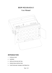
SMART SCALER TM
1) SUPPLIED EQUIPMENT
• 1 SMART SCALER TM (SMS100)
• 1 Set of 19” Brackets
• 1 AC Power supply cord
• 1 VGA cable (HD15 Male / Male)
• 1 S.VIDEO (Y/C) cable
• 1 RCA Male /Male cable
• 1 RCA Female / BNC Male adapter
• 1 5xBNC to HD15 Female cable
• 1 User’s Manual
2) GENERAL INFORMATION
The SMART SCALER ™ combines the functions of a High Resolution Video Scaler with a video switcher. In
addition, a Computer or external input is provided for direct display of your Presentations or Internet
applications.
• The SMART SCALER™ is a state of the art improved SCALER / LINE MULTIPLIER which significantly
increases the Video image resolution and brightness. The very High Quality decoder includes an Advanced Comb
Filter, an anphasized “natural” color processing, a highly robust sync. detection and a new enhanced 3D autoadaptive de-interlacing scheme (for motion artifacts), with correction of the “film to video” transfer (3/2 pulldown
for NTSC). It provides you with a “cinema like” image.
• In addition, and according to your requirements, you can continuously adjust special image parameters like the
Sharpness for details emphasis, the Stepness Enhancer for subtitle readability improvements, the Coring processor
for removing High Frequency noise found in some “VCR” tapes without affecting the bandwidth, and the Gamma
Corrector, which optimizes your CRT, DLP, LCD’s Luma response.
• The input source aspect ratio 4/3,16/9, Widescreen can be selected as well as the size of the SCREEN (4/3-16/9).
• The Frame Conversion & Time base correction provides High End A/V Pro & Home Theater solutions.
PAGE 4
ANALOG WAY
SMS100 - ED 07/01
3) INSTALLING THE SMART SCALER™
• Table Top Mounting :
The SMART SCALER™ can be used directly on a table: the unit is equipped with 4
plastic feet.
• Rack Mounting :
The SMART SCALER ™ is compatible with a 19" enclosure . Please follow the instructions
below to install the SMART SCALER™ into a 19” rack:
- Screw the supplied 19” brackets to the sides of the SMART SCALER™
- Put the SMART SCALER™ into the rack.
NOTE : the 19” front panel screws are not included.
- The openings in the top cover and in the rear panel are for cooling.
Do not cover these openings.
- Be sure that no weight is added to the SMART SCALER™ in excess of 2 kg (4.4 lbs.).
- The maximum ambient operating temperature must not exceed 40°C (105°F).
- The rack and all mounted equipment in it must be reliably grounded to national and
local electrical codes.
ANALOG WAY
SMS100 - ED 07/01
PAGE 5
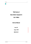
4) TECHNICAL DESCRIPTION
• FRONT PANEL
COMPUTER
: COMPUTER input selection.
COMPOSITE 1
: COMPOSITE 1 input selection (C.V1).
COMPOSITE 2
: COMPOSITE 2 input selection (C.V2).
S.VIDEO 1
: S.VIDEO 1 input selection.
S.VIDEO 2
: S.VIDEO 2 input selection.
RGB & COMPONENT
: RGB / COMPONENT (R-Y, Y, B-Y) input selection.
FREEZE
: Freeze the displayed image.
CONTROL : Allows to select items in LCD menu.
EXIT MENU
: Allows to exit from an LCD menu.
ENTER
: Allows to validate a selected item.
ON / OFF
: AC power switch (O = OFF, I = ON).
• REAR PANEL
POWER INPUT
: Standard IEC connector (100-250VAC, 1A, 50-60Hz).
REMOTE RS-232
: Standard remote control on DB9 Female connector.
COMPUTER INPUT
: Computer (PC, MAC, WORKSTATION) input on HD15 Female connector.
ROOM +12Vdc TRIGGER
: A Room command output (3.5 mm JACK female) controlled by the AC main
switch. When you switch ON your SMART SCALER ™ the ROOM output
is activated (+12 Vdc trigger), which allows to control external functions such
as Up/Down screen, or switching ON your projector.
VIDEO INPUTS
C.V 1
: COMPOSITE 1 video input on BNC connector.
C.V 2
: COMPOSITE 2 video input on BNC connector.
S.VIDEO 1
: S.VIDEO 1 (Y/C) input on 4 pin mini DIN connector.
S.VIDEO 2
: S.VIDEO 2 (Y/C) input on 2 x BNC connectors.
RGB SYNC / R-Y, Y, B-Y
: RGB/S or YUV (COMPONENT) video inputs on 3 or 4 BNC connectors.
DISPLAY OUTPUT
PAGE 6
: DATA output (RGB HV or RGB.S) on 4 or 5 BNC connectors.
ANALOG WAY
SMS100 - ED 07/01
5) STARTING
IMPORTANT : Please read all of the Safety Instructions (pages 2 & 3) before starting.
c Turn OFF all of your equipment before connecting,
d Connect the AC Power supply cord to the SMART SCALER™ and to a AC power outlet,
e Connect your video sources (VCR, DVD, camera, laser disc, ...) to the C.V1, C.V2, S.VIDEO 1, S.VIDEO 2 and
RGB.SYNC or COMPONENT (R-Y, Y, B-Y) inputs,
f Connect your computer source to the COMPUTER INPUT,
g Connect the DATA INPUT of your display device (data projector, plasma screen,...) on the "DISPLAY OUTPUT"
of the SMART SCALER™,
h Turn ON all of your input sources, the SMART SCALER™ (front panel switch) and then your display device.
i Select a source with the front panel key to display this source in output (LED turned ON).
• COMPOSITE VIDEO INPUTS (C.V1 & C.V2)
The Composite Video signal, usually called COMPOSITE or VIDEO, is available on the most video
equipment (VCR, DVD, CAMERA…), but is also the lowest in picture quality. The video standard of this signal could
be NTSC, PAL or SECAM. The signal is transmitted by a single coaxial cable, and is connected to the video equipment
with a RCA or BNC connector.
CONNECTION
ANALOG WAY
SMS100 - ED 07/01
PAGE 7
5) STARTING (continued)
• S.VIDEO INPUTS
The S.VIDEO (Super Video) signal, also called Y/C, HI-8™, or S.VHS™, is available on DVD player and
high quality VCR (S.VHS). The S.VIDEO signal in which the Luminance (Y) and Chrominance (C) information are
separately transmitted (2 wires) thereby giving a higher quality picture than the Composite video signal. The S.VIDEO
connector is usually a 4 pin Mini-DIN connector also called Oshiden™ connector.
CONNECTION
• RGB.S INPUT
The RGB.S signal, also called RGB Sync is a RGB signal with COMPOSITE sync. This signal is widely used
in broadcasting and is available on European DVD player and Satellite receiver. The RGB.S signal is transmitted with 4
coaxial cables, and also have a better picture quality than COMPOSITE and S.VIDEO signals. The RGB.S connectors
are usually BNC connectors for Broadcasting equipment, and SCART connector for DVD player and Satellite Receiver.
CONNECTION
PAGE 8
ANALOG WAY
SMS100 - ED 07/01
5) STARTING (continued)
• COMPONENT VIDEO INPUT (Y, R-Y, B-Y)
The Component Video signal, also called YUV (Y, R-Y, B-Y), or BETACAM™, is widely used in
broadcasting and is available on high-quality DVD players. The COMPONENT signal is transmitted with 3 coaxial
cables, and also have a better quality picture than COMPOSITE and S.VIDEO signals. The COMPONENT connectors
are usually RCA (x3), or BNC (x3) connectors.
CONNECTION
• COMPUTER INPUT
This input is used to pass-though any High-definition or Computer signals. The signal connected to this input is
sent directly to the display output. Also you may connect a Computer source (PC, MAC, WORKSTATION), or a high
definition source (progressive DVD player, HDTV). Use the VGA supplied cable (HD15 male/male) to connect a PC.
For the others sources you may required some adapters (not supplied).
• DISPLAY OUTPUT
The SMART SCALER™ is equipped with a 5 BNC connectors output. If your display device is equipped only
with a HD 15 connector : use the BNC to HD 15 supplied cable (please see connection scheme below).
The SMART SCALER™ can display a RGBHV (H & V Separate Sync.) or a RGBS (Composite Sync.) signal.
If your display device accept only Composite Sync, connect the C.SYNC cable to the H BNC of the SMART
SCALER™ and select COMP (Composite Sync.) in the LCD menu # 2-1 (Please see chapter 6).
CONNECTION
ANALOG WAY
SMS100 - ED 07/01
PAGE 9
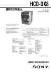
6) LCD MENU & CONTROL
6-1) LCD CONTROL BUTTONS
CONTROL button
: To control the LCD Menu please press on the EXIT / MENU or ENTER button before
adjusting with the control knobs.
EXIT / MENU button
: • From the STATUS MENU, press this button to display the CONTROL MENUS
• From the CONTROL MENUS, press this button to :
- return to the previous menu,
- return to the STATUS MENU (press several times),
- return without safeguarding the item.
ENTER button
: • From the STATUS MENU, press this button to return to the last consulted menu.
• From the CONTROL MENUS, press this button to confirm a selected item.
NOTE : When entering in the CONTROL MENUS, the LCD window will automatically display the STATUS MENU
after 60 seconds of inactivity of the front panel buttons.
6-2) LCD MENUS
• LCD DIAGRAM
LCD CONTROL MENUS
LCD STATUS MENUS
SMART SCALER
SMS100
1 input menu
OUTPUT
STATUS
INPUT
STATUS
2 output menu
3 image menu
video standard
auto manual
1 video standard
2 video status
LCD displays the
selected video status
3 RGB/YUV in
YUV
RGB/S (TTL)
RGsB (SOG)
RGBS (75 ohms)
4 comput status
LCD displays the
computer status
output sync
H&V
COMP
1 output sync
2 output format
LCD displays the
output format liste
3 output rate
internal rate
video in rate
4 type of screen
screen 4/3
screen 16/9
1
2
3
4
5
6
H position
V position
H size
V size
u/overscan
aspect ratio
7 brightness
8 contrast
9 color
10 hue
11 image process
4/3 standard
letter box
WS anamorphic
Gamma
Sharpness
Subtitle
Coring
Adapt black
12 Preset
4 control menu
PAGE 10
1 languages
English
2 panel locking
all unlock
all lock
3 black delay
4 version
5 default value
short
ANALOG WAY
SMS100 - ED 07/01
no
long
yes
video input
selection
standard
selection
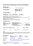
6) LCD MENU & CONTROL (continued)
6-2) LCD MENUS (continued)
• LCD STATUS MENUS
c
SMART SCALER
d
SMS 100
OUTPUT
f
SYNC= H&V
MAIN STATUS MENU
e
OUTPUT STATUS MENU
g
INPUT STATUS MENU
800 X 600 L
INPUT
h
S.VIDEO 1
NTSC (auto)
c PRODUCT NAME
d PRODUCT MODEL
e OUTPUT SYNC TYPE (H&V = H &V Separate Sync, COMP = Composite Sync)
f OUTPUT FORMAT
g DISPLAYED INPUT
h VIDEO STANDARD OF THE DISPLAYED INPUT
• LCD CONTROL MENUS
1 [INPUT MENU] + ENTER
1-1 [VIDEO STANDARD] + ENTER
Select an item with + ENTER
[AUTO] = Automatic recognition of the video standard for all inputs.
PAL / NTSC / SECAM / Black & White are detected automatically; if not, please use the [MANUAL] setting.
[MANUAL] = Manual selection of the video standard for each input.
1. Select an input with + ENTER
• [C.VIDEO 1]
• [C.VIDEO 2]
• [S.VIDEO 1]
• [S.VIDEO 2]
2. Select the video standard with + ENTER
• [AUTO] = Automatic recognition.
• [NTSC] = NTSC detection only.
• [PAL] = PAL detection only.
• [SECAM] = SECAM detection only.
• [Black & White] = Black and White detection only.
ANALOG WAY
SMS100 - ED 07/01
PAGE 11
6) LCD MENU & CONTROL (continued)
6-2) LCD MENUS (continued)
1-2 [VIDEO STATUS] + ENTER
Indicates the status of the selected video input.
• [S.VIDEO 1] = Selected input.
• [NTSC] = Video standard of this input.
1-3 [RGB/YUV IN] + ENTER
Select the video signal connected to the RGB / YUV (R-Y / Y / B-Y) input :
• [YUV] = Component (YUV) video signal.
• [RGB/S (TTL)] = RGB/S video signal with TTL Sync.
• [RGsB (SOG)] = RGsB video signal with Sync. On Green.
• [RGB/S (75 Ω)] = RGB/S with an analog Sync. (0.3 Vp/p).
1-4 [COMPUT STATUS] + ENTER
Indicates the status of the computer
• [COMP] = Composite Sync. or [H&V] = H & V Separate Sync.
• [SXGA] = Name of the input format.
• [64.0K / 60Hz] = Input line frequency / Input frame frequency (kHz / Hz).
2 [OUTPUT MENU] + ENTER
2-1 [OUTPUT SYNC] + ENTER
Select the Output Sync. type with + ENTER
• [H&V] = H & V Separate Sync.
• [COMP] = Composite Sync.
2-2 [OUTPUT FORMAT] + ENTER
• If [OUTPUT RATE] = [VIDEO IN RATE], the LCD window displays the following formats :
Select an output format with + ENTER
• 640 x 480L (Line doubler: 480p/59.94 Hz or 576p/50 Hz- 4/3)
• 852 x 480L (Plasma 42” at 50 Hz or 59.94 Hz- 16/9)
• 800 x 600L (SVGA at 50 Hz or 59.94 Hz- 4/3)
• 1024 x 768L (XGA2 at 50 Hz or 59.94 Hz- 4/3)
• 1280 x 720L (HDTV 720p at 50 Hz or 59.94 Hz- 16/9)
• 1280 x 768L (Plasma 50” at 50 Hz or 59.94 Hz- 16/9)
• 1280 x 960L (Line Quadrupler at 50 Hz or 59.94 Hz- 4/3)
• 1280 x 1024L (SXGA at 50 Hz or 59.94 Hz)
• 1365 x 1024L (D-ILA at 50 Hz or 59.94 Hz- 4/3)
NOTE: The output rate is 50 Hz for PAL & SECAM video inputs, or 59.94 Hz for NTSC video inputs.
PAGE 12
ANALOG WAY
SMS100 - ED 07/01
6) LCD MENU & CONTROL (continued)
6-2) LCD MENUS (continued)
• If [OUTPUT RATE] = [INTERNAL RATE], the LCD window displays the following formats :
Select an output format with + ENTER
• VGA 60 Hz (640 x 480 at 60 Hz)
• Plasma 42” 60 Hz (852 x 480 at 60 Hz)
• SVGA 60 Hz (800 x 600 at 60 Hz)
• MAC 66 Hz (640 x 480 at 66 Hz)
• XGA 60 Hz (1024 x 768 at 60 Hz)
• Plasma 50” 56 Hz (1280 x 768 at 60 Hz)
• SXGA 60 Hz (1280 x 1024 at 60 Hz)
• VGA 75 Hz (640 x 480 at 75 Hz)
• Plasma 42” 72 Hz (852 x 480 at 72 Hz)
• SVGA 75 Hz (800 x 600 at 75 Hz)
• MAC 16” 75Hz (832 x 624 at 75 Hz)
• XGA 75 Hz (1024 x 768 at 75 Hz)
• Plasma 50” 75Hz (1280 x 768 at 75 Hz)
• SXGA 75 Hz (1280 x 1024 at 75 Hz)
NOTE : For fixed pixel display device (DMD, LCD, PLASMA…), always select the output format corresponding
to the native resolution of the display device. This way, the display device will not have to scale the image
and the result will be better.
2-3 [OUTPUT RATE] + ENTER
Select an item with + ENTER
• [INTERNAL RATE] = The output Frame Rate is 60 Hz or 75 Hz depending of the selected OUTPUT
format (LCD menu # 2-2). A high level frame frequency gives a better visual
aspect when displaying static pictures.
• [VIDEO IN RATE] =
The Output Frame Rate is identical to the Video Input Frame Rate : 50 Hz frame
rate if the video is PAL or SECAM and 59.94 Hz if the video is NTSC.
This function allows to improve the motion pictures.
2-4 [TYPE OF SCREEN]
Select an item with + ENTER
• [4/3] = if your image is displayed on a 4/3 screen.
• [16/9] = if your image is displayed on a 16/9 screen.
NOTE: The 16/9 type of screen mode does not support the NTSC 4/3 standard image if the selected Output
format is 1280 x 960L, 1280 x 1024L, 1365 x 1024L (D-ILA), XGA 75Hz or SXGA.
3 [IMAGE MENU] + ENTER
NOTE : This menu is available and active only on the selected video source displayed in output. This menu is not available
²
for the COMPUTER INPUT. The image settings and adjustments can be different and memorized for each video
input separately.
3-1 [H POSITION] + ENTER
Adjust the Horizontal position with + ENTER
3-2 [V POSITION] + ENTER
Adjust the Vertical position with + ENTER
ANALOG WAY
SMS100 - ED 07/01
PAGE 13
6) LCD MENU & CONTROL (continued)
6-2) LCD MENUS (continued)
3-3 [H SIZE] + ENTER
Adjust the Horizontal size with + ENTER
3-4 [V SIZE] + ENTER
Adjust the Vertical size with + ENTER
3-5 [U / OVER SCAN] + ENTER
Select Underscan or Overscan with + ENTER
• [UNDERSCAN] = Output image is full screen.
• [OVERSCAN] = Output image is 10% bigger than in Underscan mode.
3-6
[ASPECT RATIO] + ENTER
Select an Aspect Ratio with + ENTER
• [4/3 standard] = 4/3 input Aspect Ratio.
• [letterbox] = 16/9 Letterbox Aspect Ratio.
• [WS anamorphic] = Widescreen anamorphic (to be used only if your DVD player is set in 16/9)
3-7
[BRIGHTNESS] + ENTER
Adjust the Brightness with + ENTER
3-8
[CONTRAST] + ENTER
Adjust the Contrast with + ENTER
3-9
[COLOR] + ENTER
Adjust the Color with + ENTER
3-10 [HUE] + ENTER
Adjust the Tint of the picture (NTSC only) with + ENTER
3-11 [IMAGE PROCESS] + ENTER
Select a function and adjust with + ENTER, and valid with ENTER
• GAMMA :
Gives greater depth to darker portions of the image for more exciting theater experience
or brightens dark portions for the image for more enhanced presentations.
• SHARPNESS : Increase the details of the image.
• SUBTITLE : Increase the readability of subtitles.
• CORING :Reduce the noise of VCR tape.
• ADAPTIVE BLACK : Automatic black level correction.
3-12 [PRESET] + ENTER
• [YES] = Erases all of the Image Settings (#3-1, #3-2, ... #3-11) and sets them back to the Factory Settings.
• [NO] = Do not erase the Image Settings memorized.
PAGE 14
ANALOG WAY
SMS100 - ED 07/01
6) LCD MENU & CONTROL (continued)
6-2) LCD MENUS (continued)
4 [CONTROL MENU] + ENTER
4-1 [LANGUAGES] + ENTER
4-2
[PANEL LOCKING] + ENTER
Select which locking function you need with + ENTER
• [ALL UNLOCK] = All front panel switches are Unlocked.
• [ALL LOCK] = All front panel switches are Locked.
4-3 [BLACK DELAY] + ENTER
This function allows to adjust the duration of the black when switching between sources.
• [SHORT] = 1 second delay
• [LONG] = 3 seconds delay.
4-4 [VERSION] + ENTER
Status of the internal firmware : K = xxxx
L = xxxx
R = xxxx
V = xxxx
4-5 [DEFAULT VALUE] + ENTER
• [NO] = No Adjustments and Settings are modified.
• [YES] = Clears the following Adjustments and sets them to the Factory Settings.
1-1 VIDEO STANDARD = Automatic
1-3 RGB / YUV IN = YUV (Component)
2-1 OUTPUT SYNC = H & V Separate Sync.
2-2 OUTPUT FORMAT = 800 x 600L
2-3 OUTPUT RATE = VIDEO IN RATE
2-4 TYPE OF SCREEN = 4/3
3-5 U / OVER SCAN = UNDERSCAN
3-6 ASPECT RATIO = 4/3 STANDARD
3-12 PRESET = YES
4-3 BLACK DELAY = SHORT
ANALOG WAY
SMS100 - ED 07/01
PAGE 15
7) OPERATING MODE
7-1) INSTALLATION (Please see section 3 & 5).
7-2) SETTINGS
c We recommend to reset the SMART SCALER™ to all of its default values, with the LCD menu # 4-5, before
beginning
d Select the type of video signal connected to the RGB/YUV input (LCD menu # 1-3).
e Select the type of screen (4/3 or 16/9) in LCD menu # 2-4.
f Select the output sync. type which correspond to your display device (LCD menu # 2-1).
g Select the synchronization mode (LCD menu # 2-3). Please see the synchronization mode table below.
h Select an Output Format (LCD menu # 2-4). Please see the synchronization mode table below.
NOTE : For fixed panel display device (DMD, LCD, PLASMA…), select always the output format corresponding to
the native resolution of your display device. Thus, the display device will not have to scale the image and the
result will be better.
SYNCHRONIZATION MODE TABLE
THE SCALER FOLLOW MODE
(LCD menu # 2-3= VIDEO IN RATE)
THE SCALER MODE
(LCD menu # 2-3 = INTERNAL RATE)
APPLICATIONS
Movie and motion pictures display.
Video presentation (static pictures).
OUTPUT RATE
Locked on the Frame Rate of the selected video input
(50 Hz if PAL or SECAM and 59.94 Hz if NTSC)
• 640 x 480 (4/3 - VGA at 50 or 59.94 Hz)
• 852 x 480 (16/9 - Plasma 42” at 50 or 59.94 Hz)
• 800 x 600 (4/3 - SVGA at 50 or 59.94 Hz)
• 1024 x 768 (4/3 - XGA2 at 50 or 59.94 Hz)
• 1280 x 720 (16/9 - HDTV at 50 or 59.94 Hz)
• 1280 x 768 (16/9 - Plasma 50” at 50 or 59.94 Hz)
• 1280 x 960 (4/3 - Line quadrupler at 50 or 59.94 Hz)
• 1280 x 1024 (4/3 - SXGA at 50 or 59.94 Hz)
• 1365 x 1024 (4/3 - D-ILA at 50 or 59.94 Hz)
Generated by the SMART SCALER ™ (60 Hz
or 75 Hz)
• VGA (640 x 480) at 60 Hz or 75 Hz
• PLASMA 42" (852 x 480) at 60 Hz or 72 Hz
• SVGA (800 x 600) at 60Hz or 75Hz
• MAC (640 x480) at 66Hz or 75Hz
• XGA2 (1024 x 768) at 60Hz or 75 Hz
• PLASMA 50" (1280 x 768) at 56 Hz or 75 Hz
• SXGA (1280 x 1024) at 60 Hz or 75 Hz
OUTPUT FORMAT
AVAILABLE
(LCD menu # 2-2)
7-3) IMAGE ADJUSTMENTS
For all input sources connected to the SMART SCALER™, make the following adjustments: :
c Select the aspect ratio of your input source (LCD menu #3-6)
d Adjust the vertical and horizontal position (LCD menu # 3-1 & 3-2)
e Make the others adjustments, if necessary, available in LCD menu # 3 (color, brightness, image process…)
NOTE : The image adjustments are only active for the selected video input.
NOTE : To preset your image adjustment, select one video to display in output, then use the LCD
menu # 3-12 (Preset).
PAGE 16
ANALOG WAY
SMS100 - ED 07/01
8) TECHNICAL SPECIFICATIONS
8-1) VIDEO INPUTS
• RGB.S (4 BNC CONNECTORS)
15.625 kHz / 50 Hz .... 15.735 kHz / 60 Hz (625L .....525L)
Levels
: R, G, B = 3 x 0.7 Vp/p
: SYNC. = 0.3 Vp/p or TTL
Impedance
: RGB = 75 Ohms
SYNC. = 75 Ohms or Hi-Z
• COMPONENT (YUV) - R-Y / Y / B-Y (3 BNC CONNECTORS)
15.625 kHz / 50 Hz .... 15.735 kHz / 60 Hz (625L .....525L)
Levels
: Y = 0.3 Vp/p (Sync.) + 0.7 Vp/p (Luma)
: R-Y = 0.7 Vp/p / B-Y = 0.7 Vp/p
Impedance
: Y, R-Y, B-Y = 75 Ohms
• S.VIDEO (Y/C) (4 PIN MINI DIN CONNECTOR & 2 BNC CONNECTORS)
PAL / SECAM 15.625 kHz / 50 Hz (625L)
NTSC 3.58 MHz / 4.43 MHz 15.735 kHz / 60 Hz (525L)
Levels
: Y = 1 Vp/p (0.7 Vp/p Luma + 0.3 Vp/p Sync.)
: C = 0.3 Vp/p (Chroma Burst)
Impedance
: 75 Ohms
• COMPOSITE VIDEO (BNC CONNECTOR)
PAL / SECAM 15.625 kHz / 50 Hz (625L)
NTSC 3.58MHz / 4.43 MHz 15.735 kHz / 60 Hz (525L)
Level
: 1 Vp/p (0.7 Vp/p Luma + 0.3 Vp/p Sync.)
Impedance
: 75 Ohms
8-2) COMPUTER INPUT (15 PINS HD F CONNECTORS)
Hardware compatibility
: Line frequency : from 15 kHz to 100 kHz
: Frame frequency : from 24 Hz to 120 Hz
NOTE : The COMPUTER input is passed directly through to the DISPLAYED OUTPUT connector. You can also
connect a Computer source (PC, MAC, WORKSTATION) or a High Definition video source (progressive
DVD player, HDTV) to the COMPUTER INPUT.
8-3) DISPLAY OUTPUT (4/5 BNC CONNECTORS)
Levels
: R, G, B = 0.7 Vp/p
: Sync. : H & V separated = TTL
: COMP. Sync. = TTL
Impedance
: R, G, B, H & V and COMP. Sync. = 75 Ohms
Format
: • If computer input is selected : the output format is the same as the Computer input,
• If a video input is selected : the output format is one of the format available in the
LCD menu # 2-2.
ANALOG WAY
SMS100 - ED 07/01
PAGE 17
8) TECHNICAL SPECIFICATIONS (continued)
8-4) REMOTE PORT (DB 9 female connector)
Level
: RS-232
Data Rate
: 9600 Bauds, 8 data bits, 1 stop bit, no parity bit
8-5) ROOM COMMAND (3.5 jack female connector)
NOTE : The ROOM (+12 Vdc Trigger) Command is activated by the AC Power Switch (ON/OFF).
Command level
: • If AC Power Switch = ON : command = + 12 Vdc
• If AC Power Switch = OFF : command = 0 Vdc
Output Current
: 0.1 A max at + 12 Vdc
Connection
3.5 JACK MALE CONNECTOR (STEREO or MONO)
Command
Ground
8-6) ENVIRONMENTAL
Power Supply
: Internal CE / UL / CSA / IEC 950 (50 W), universal, automatic
: Input : 100 VAC to 250 VAC ; 50-60 Hz ; I = 1 A Max.
Storage Temperature
: -25°C to +85°C
Operating temperature
: 0°C to 50°C
Maximum ambient operating temperature
: < 40°C
Hygrometry
: 10% to 80% (without condensation)
Dimensions
: D 300 x W 440 x H 44mm / D 11.8" x W 17.3" x H 1.74"
Weight
: 3.4 kg / 7.48 lbs.
PAGE 18
ANALOG WAY
SMS100 - ED 07/01
9) REMOTE CONTROL RS-232
9-1) CONNECTION
• CONNECTING THE RS-232
• Connect the serial port of your Controlling Device (computer) to the REMOTE CONTROL
(RS-232) connector (DB 9 F) of the SMART SCALER™ with a straight cable (DB 9 Female / DB 9 Male).
PC
SMS100
• PIN-OUT
Pin #
2
3
5
Functions
TRANSMIT DATA (Tx)
RECEIVE DATA (Rx)
GROUND (Gnd)
DB 9 female
(Rear panel of the SMART SCALER™)
• SPEED TRANSMISSION : 9600 Bauds, 8 Data bits, 1 Stop bit, No Parity bit.
ANALOG WAY
SMS100 - ED 07/01
PAGE 19
9) REMOTE CONTROL RS-232 (continued)
9-2) HOST / SMART SCALER™ COMMUNICATION
If you need to use your own Control Software program with a PC or WORKSTATION by a RS-232 port,
the SMART SCALER™ allows to communicate by simple transmit and receive ASCII codes.
The SMART SCALER™ treats any character that it receives on the RS-232 as a possible command but accepts only
legal commands.
There are no codes to say that a command is coming, or that a command has ended.
A command can be a single character typed on a keyboard and does not require any special character before or after
it. (it is not necessary to press "ENTER" on the keyboard).
Simple commands can be from a PC or any other controlling device.
When the SMART SCALER™ receives a valid command, it will execute the command and send a response back to
the host device.
If the command is invalid, an error response will be returned to the host.
All responses to the host end with a carriage return and a line feed (CR / LF) signaling the end of the response
character string.
• PROTOCOL : Simple character
• CONTROLS STRUCTURE
Controls are usually composed of a numerical value followed by the letter of the command.
The letter used without a numerical value returns the current setting of the command.
Please see "COMMANDS AND RESPONSES TABLE".
- COMMANDS : Y, I, r, w, x, y, z, O, o, u, H, V, W, S, B, C, s, T, b, j, A, Q, N.
( PARAMETER )
< COMMAND >
a character (Usually a letter)
Without parameter :
Reads back the current value
ex : H ⇒ HPOS10 ↵
With a numerical parameter :
Sets a new value
ex : 20H ⇒ HPOS20 ↵
- COMMANDS (Read only : STATUS) : U, l, t, P, p, v, n, ?, K, L, R and X.
( PARAMETER )
< COMMAND >
a character (Usually a letter)
Without parameter :
PAGE 20
Reads back the current value
ex : I ⇒ ICHAN1 ↵
ANALOG WAY
SMS100 - ED 07/01
9) REMOTE CONTROL RS-232 (continued)
9-2) HOST / SMART SCALER™ COMMUNICATION (continued)
• COMMANDS AND RESPONSES TABLE
The following table resumes commands which are recognized as valid and the responses that will be returned to
the host (on the RS-232 port).
COMMAND
RESPONSE
COMMAND
ASCII
TO
HOST
DESCRIPTION
INPUT COMMANDS
I
ICHAN
VALUE
EXAMPLE
MIN
MAX
COMMAND
RESPONSE
SELECTED INPUT
1
7
5I
ICHAN5
0
3
r
IRGB1
0
4
w
ISTDC10
r
IRGB
w
ISTDC1
VIDEO TYPE OF RGB/YUV
INPUT
INPUT STANDARD C.VIDEO 1
x
ISTDC2
INPUT STANDARD C.VIDEO 2
0
4
x
ISTDC21
y
ISTDS1
INPUT STANDARD S.VIDEO 1
0
4
y
ISTDS14
z
ISTDS2
INPUT STANDARD S.VIDEO 2
0
4
z
ISTDS21
ACTION EXPLANATION
SELECTS S.VIDEO 1 INPUT
READS VIDEO TYPE OF THE
RGB/YUV INPUT
READS THE VIDEO STANDARD
DETECTION
READS THE VIDEO STANDARD
DETECTION
READS THE VIDEO STANDARD
DETECTION
READS THE VIDEO STANDARD
DETECTION
OUTPUT COMMANDS
O
OFMT
OUTPUT FORMAT
0
16
O
OFMT2
READS THE OUTPUT FORMAT
o
OSIG
OUTPUT SYNC. TYPE
0
1
1o
OSIG1
u
SSYNC
OUTPUT FRAME RATE
0
3
3u
SSYNC3
SETS THE OUTPUT SYNC.
TO COMP. SYNC.
SETS THE OUTPUT FRAME
RATE TO VIDEO IN RATE
20H
HPOS20
SETS H. POSITION TO 20
IMAGE COMMANDS (VIDEO ONLY)
H
HPOS
HORIZONTAL POSITION
0
255
V
VPOS
VERTICAL POSITION
0
255
V
VPOS73
READS V POSITION
W
HSIZ
HORIZONTAL SIZE
0
255
W
HSIZ128
READS H WIDTH
S
VSIZ
VERTICAL SIZE
0
255
157S
VSIZ157
SETS V SIZE TO 157
B
BRGT
BRIGHTNESS ADJUSTMENT
0
255
B
BRGT15
READS BRIGHTNESS LEVEL
C
CONTR
CONTRAST ADJUSTMENT
0
255
C
CONTR50
s
COLOR
COLOR SATURATION
0
255
s
COLOR125 READS COLOR SATURATION
LEVEL
T
HUE
HUE ADJUSTMENT (NTSC ONLY)
0
255
T
b
IASP
ASPECT RATIO
0
2
2b
IASP2
j
GAMMA
GAMMA ADJUSTMENT
0
63
j
GAMMA0
READS GAMMA LEVEL
A
SHARP
SHARPNESS ADJUSTMENT
0
63
A
SHARP20
READS SHARPNESS LEVEL
Q
N
SUBTT
NOISE
SUBTITLES ENHANCEMENT
NOISE REDUCTION
0
0
63
63
Q
N
SUBTT55
NOISE10
READS SUBTITLE LEVEL
READS NOISE REDUCTION
LEVEL
HUE120
READS CONTRAST LEVEL
READS HUE LEVEL
SETS ASPECT RATIO TO 16/9
STATUS COMMANDS (READ ONLY)
U
UNIT
MEASURES UNITY IN kHz
0
65535
U
UNIT----
READS UNITY OF MEASURE
l
CLD
0
65535
l
CLD----
t
CFD
0
65535
t
CFD----
P
CSTA
DURATION OF A COMPUTER
LINE
NUMBER OF LINE PER FIELD
OF COMPUTER
COMPUTER STATUS
0
31
P
CSTA----
READS LINE FREQUENCY OF
SELECTED COMPUTER
READS LINE PER FIELD OF
SELECTED COMPUTER
READS COMPUTER STATUS
p
VSTA
VIDEO STATUS
0
16
p
VSTA13
READS THE VIDEO STATUS
v
VCHAN
0
7
v
VCHAN7
n
SCSTA
INPUT NUMBER OF THE VIDEO
WHICH STATUS IS GIVEN
SCALER SYNCHRONIZATION
0
3
n
SCSTA3
VIDEO STATUS IS FOR
RGB/YUV INPUT
VIDEO IN RATE
FREEZE ACTION
MISCELLANEOUS COMMANDS
Y
CMD
MISCELLANEOUS CONTROL
0
32768
128Y
CMD128
?
DEV
DEVICE TYPE
0
65535
?
DEV13
K
K_
"K" FIRMWARE VERSION
0
65535
K
K_
READS DEVICE TYPE
(13 = SMART SCALER™)
READS K VERSION
L
L_
"L" FIRMWARE VERSION
0
65535
L
L_
READS L VERSION
R
R_
"R" FIRMWARE VERSION
0
65535
R
R_
READS R VERSION
X
V_
"X" FIRMWARE VERSION
0
65535
X
V_
READS X VERSION
ANALOG WAY
SMS100 - ED 07/01
PAGE 21
9) REMOTE CONTROL RS-232 (continued)
9-2) HOST / SMART SCALER™ COMMUNICATION (continued)
• ERROR RESPONSES :
When the SMART SCALER™ receives from the host an invalid command or value, it returns an error response:
E10 ↵
E13 ↵
Invalid command (See "COMMAND" column).
Invalid value (See "VALUE" column).
• COMMANDS DESCRIPTION
Values sent or received are in decimal. Depending on the command letter, the value can be used as a linear control (ex :
255W to set the horizontal size to the maximum) or as a set of bits (ex : P command with multiple controls). In this case,
the value must be converted in binary base to understand every bit action.
EXAMPLE Host receives message CSTA3 (P command)
Decimal value 3 = Binary value 011
3 = (4 x 0) + (2 x 1) + (1 x 1)
bit 0 = 1 means Sync. detected.
bit 1 = 1 means Comp. Sync. detected.
bit 2 = 0 means non interlaced format detected.
c INPUT COMMANDS :
• I command is used to select an input.
DECIMAL VALUE
1
3
4
5
6
7
INPUT # SELECTION
COMPUTER
C.VIDEO 1
C.VIDEO 2
S.VIDEO 1
S.VIDEO 2
RGB / YUV
RESPONSE
ICHAN1
ICHAN3
ICHAN4
ICHAN5
ICHAN6
ICHAN7
• r command is used to select the video type of the RGB/YUV input.
DECIMAL VALUE
0
1
2
3
SELECTION
YUV
RGB/S (TTL)
RGsB (SOG)
RGB/S (75Ω)
RESPONSE
IRGB0
IRGB1
IRGB2
IRGB3
• w, x, y, z commands are used to select the video standard of the C.VIDEO 1, C.VIDEO 2, S.VIDEO 1
and S.VIDEO 2 input.
DECIMAL VALUE
0
1
2
3
4
PAGE 22
SELECTION
AUTOMATIC
NTSC (3.58 / 60Hz)
PAL (4.43 / 50Hz)
SECAM
BLACK & WHITE
ANALOG WAY
SMS100 - ED 07/01
RESPONSE
ISTD__0
ISTD__1
ISTD__2
ISTD__3
ISTD__4
9) REMOTE CONTROL RS-232 (continued)
9-2) HOST / SMART SCALER™ COMMUNICATION (continued)
d OUTPUT COMMANDS :
• o command is used to select the Output Sync. type.
DECIMAL VALUE
SELECTION
(OUTPUT SYNC TYPE)
SEPARATE H & V SYNC.
COMPOSITE SYNC.
0
1
RESPONSE
OSIG0
OSIG1
• O command is used to select the output format.
Use the following table when the u command (Output Frame Rate) is set on Video In Rate (SSYNC3).
DECIMAL VALUE
0
1
2
4
5
6
14
15
16
SELECTION (OUTPUT FORMAT)
VGA (640 x 480) at 50Hz or 59.94 Hz
PLASMA 42” (852 x 480) at 50Hz or 59.94 Hz
SVGA (800 x 600) at 50Hz or 59.94 Hz
XGA (1024 x 768) at 50Hz or 59.94 Hz
PLASMA 50” (1280 x 768) at 50Hz or 59.94 Hz
SXGA (1280 x 1024) at 50Hz or 59.94 Hz
HDTV 720 P (1280 x 720) at 50Hz or 59.94 Hz
QUAD 960 (1280 x 960) at 50Hz or 59.94 Hz
D-ILA (1365 x 1024) at 50Hz or 59.94 Hz
RESPONSE
OFMT0
OFMT1
OFMT2
OFMT4
OFMT5
OFMT6
OFMT14
OFMT15
OFMT16
Use the following table when the u command (Output Frame Rate) is set on Internal Rate (SSYNC0).
DECIMAL VALUE
0
1
2
3
4
5
6
7
8
9
10
11
12
13
SELECTION (OUTPUT FORMAT)
VGA (640 x 480) at 60Hz
PLASMA 42” (852 x 480) at 60Hz
SVGA (800 x 600) at 60Hz
MAC (640 x 480) at 66Hz
XGA (1024 x 768) at 60Hz
PLASMA 50” (1280 x 768) at 56Hz
SXGA (1280 x 1024) at 60Hz
VGA (640 x 480) at 75Hz
PLASMA 42” (852 x 480) at 72Hz
SVGA (800 x 600) at 75Hz
MAC 16” (832 x 624) at 75Hz
XGA (1024 x 768) at 75Hz
PLASMA 50” (1280 x 768) at 75Hz
SXGA (1280 x 1024) at 75Hz
RESPONSE
OFMT0
OFMT1
OFMT2
OFMT3
OFMT4
OFMT5
OFMT6
OFMT7
OFMT8
OFMT9
OFMT10
OFMT11
OFMT12
OFMT13
• u command is used to select the Output Frame Rate.
DECIMAL VALUE
0
3
SELECTION
(OUTPUT RATE)
INTERNAL RATE
VIDEO IN RATE
ANALOG WAY
SMS100 - ED 07/01
RESPONSE
SSYNC0
SSYNC3
PAGE 23
9) REMOTE CONTROL RS-232 (continued)
9-2) HOST / SMART SCALER™ COMMUNICATION (continued)
e IMAGE COMMANDS
The following commands are active only on the selected (displayed) video input.
They are not active for the COMPUTER input.
• H, V, W, S, B, C, s, T, commands are used to control the output adjustments.
0 = minimum
255 = maximum
• b command is used to select the video input aspect ratio.
DECIMAL VALUE
0
1
2
SELECTION OF ASPECT RATIO
4/3
16/9 letterbox
Widescreen Anamorphic
RESPONSE
IASP0
IASP1
IASP2
• j, A, Q, N commands are used to control the output adjustments.
0 = minimum
63 = maximum
f STATUS COMMANDS (READ ONLY)
This control family is read only ; it cannot be preceded by a value.
• U command returns the UNIT value, used to calculate the computer line and frame frequency.
• l command returns the Computer Line Duration (CLD value).
The following formula allows to calculate input line frequency in kHz.
UNIT VALUE
CLD VALUE
= Input line frequency in kHz.
• t command returns the Computer lines per Frame (CFD value).
The following formula allows to calculate the computer input frame frequency in Hz.
INPUT LINE FREQUENCY (Hz) = Input frame frequency in Hz.
CFD VALUE
PAGE 24
ANALOG WAY
SMS100 - ED 07/01
9) REMOTE CONTROL RS-232 (continued)
9-2) HOST / SMART SCALER™ COMMUNICATION (continued)
• P command returns the Computer status. (RESPONSE : CSTA__).
Bit 2
(4)
Bit 1
(2)
Bit 0
(1)
0 = No sync. detected
1 = Sync. detected
0 = H & V sync. detected
1 = COMP sync. detected
0 = Non interlaced format
1 = Interlaced format
• p command returns the video status. (RESPONSE : VSTA__).
DECIMAL
VALUE
0
1
2
3
4
5
6
7
8
VIDEO STATUS
NO VIDEO
WRONG SIGNAL
NTSC 3.58 60 Hz
NTSC 3.58 50 Hz
NTSC 4.43 60 Hz
NTSC 4.43 50 Hz
PAL
3.58
60 Hz
PAL
3.58
50 Hz
PAL
4.43
60 Hz
RESPONSE
VSTA0
VSTA1
VSTA2
VSTA3
VSTA4
VSTA5
VSTA6
VSTA7
VSTA8
DECIMAL
VALUE
9
10
11
12
13
14
15
16
VIDEO STATUS
PAL 4.43
SECAM
B&W
B&W
YUV
YUV
RGB
RGB
50 Hz
50 Hz
50 Hz
60 Hz
50 Hz
60 Hz
50 Hz
60 Hz
RESPONSE
VSTA9
VSTA10
VSTA11
VSTA12
VSTA13
VSTA14
VSTA15
VSTA16
• v command is used to know the number of the video input which status is displayed. (RESPONSE : VCHAN_).
DECIMAL VALUE
0
3
4
5
6
7
STATUS OF VIDEO #
NO VIDEO SELECTED
C.VIDEO 1
C.VIDEO 2
S.VIDEO 1
S.VIDEO 2
RGB / YUV
RESPONSE
VCHAN0
VCHAN3
VCHAN4
VCHAN5
VCHAN6
VCHAN7
• n command is used to know the reference of the Output Frame Rate. (RESPONSE : SCSTA_).
DECIMAL VALUE
0
3
STATUS OF FRAME RATE
INTERNAL RATE
VIDEO IN RATE
ANALOG WAY
SMS100 - ED 07/01
RESPONSE
SCSTA0
SCSTA3
PAGE 25
9) REMOTE CONTROL RS-232 (continued)
9-2) HOST / SMART SCALER™ COMMUNICATION (continued)
g MISCELLANEOUS COMMANDS
• Y command is used to control different menus like the FRONT PANEL LOCK, the FREEZE…
(RESPONSE : CMD----).
Bit 15 Bit 14 Bit 13 Bit 12 Bit 11 Bit 10 Bit 9
(32768) (16384) (8192) (4096) (2048) (1024) (512)
Bit 8
(256)
Bit 7
(128)
Bit 6
(64)
Bit 5
(32)
Bit 4
(16)
Bit 3
(8)
Bit 2
(4)
Bit 1
(2)
Bit 0
(1)
Reserved
Reserved
0 = Adaptive Black OFF
1 = Adaptive Black ON
1 = Default value (action)
1 = Image Preset (action)
Please see LCD Menu 3-12
00 = Unlock (action)
01 = All lock (action)
1 = Freeze (action)
0 = Underscan image (action)
1 = Overscan image (action)
Reserved for manufacturer
Duration of the Black Delay
0 = Short time (action)
1 = Long time (action)
Reserved for manufacturer
Reserved for manufacturer
Reserved for manufacturer
Reserved for manufacturer
0 = Screen 4/3 (action)
1 = Screen 16/9 (action)
• ?, K, R, L, X, commands are the status of the device’s internal firmware (read only).
PAGE 26
ANALOG WAY
SMS100 - ED 07/01
9) REMOTE CONTROL RS-232 (continued)
9-2) HOST / SMART SCALER™ COMMUNICATION (continued)
ASCII / HEX / DEC TABLE
ASCII
HEX
DEC
ASCII
HEX
DEC
ASCII
HEX
DEC
space
!
"
#
$
%
&
’
(
)
*
+
,
.
/
0
1
2
3
4
5
6
7
8
9
:
;
<
=
>
?
20
21
22
23
24
25
26
27
28
29
2A
2B
2C
2D
2E
2F
30
31
32
33
34
35
36
37
38
39
3A
3B
3C
3D
3E
3F
32
33
34
35
36
37
38
39
40
41
42
43
44
45
46
47
48
49
50
51
52
53
54
55
56
57
58
59
60
61
62
63
@
A
B
C
D
E
F
G
H
I
J
K
L
M
N
O
P
Q
R
S
T
U
V
W
X
Y
Z
[
\
]
^
40
41
42
43
44
45
46
47
48
49
4A
4B
4C
4D
4E
4F
50
51
52
53
54
55
56
57
58
59
5A
5B
5C
5D
5E
5F
64
65
66
67
68
69
70
71
72
73
74
75
76
77
78
79
80
81
82
83
84
85
86
87
88
89
90
91
92
93
94
95
`
a
b
c
d
e
f
g
h
i
j
k
l
m
n
o
p
q
r
s
t
u
v
w
x
y
z
{
|
}
60
61
62
63
64
65
66
67
68
69
6A
6B
6C
6D
6E
6F
70
71
72
73
74
75
76
77
78
79
7A
7B
7C
7D
7E
7F
96
97
98
99
100
101
102
103
104
105
106
107
108
109
110
111
112
113
114
115
116
117
118
119
120
121
122
123
124
125
126
127
_
ANALOG WAY
SMS100 - ED 07/01
~
DEL
PAGE 27
10) TROUBLESHOOTING
SYMPTOM
• NO POWER
The LCD is OFF
• NO PICTURE
The LCD input status
displays “No video”.
For example :S.Video 1 =
No video
CAUSE
CORRECTION
• The power cord is disconnect.
PLEASE SEE
• Connect the AC power cord to the
• Chapter 5.
SMART SCALER and to the power outlet.
• Press the main switch on the front panel. • Chapter 5.
• The SMART SCALER ™ is
“POWER OFF”.
• The input source is not selected • Select the input source, with the front
correctly.
panel push button, according to the
equipment connected to the SMART
SCALER ™.
• The input source is OFF.
• Powered ON the input source.
• Chapter 5.
• Input source
user’s manual.
• The input source is
• Connect the input source to the SMART • Chapter 5.
SCALER ™.
disconnected.
• The display device is OFF.
• Powered ON the display device.
• Display device
• NO PICTURE
user’s manual.
The LCD input status
• The display device is
• Connect the DISPLAY OUTPUT of the • Display device
displays the right status of disconnect.
SMART SCALER ™ to the PC/RGB
user’s manual.
the video. (For example :
input of your display device.
S.Video 1 = NTSC) but no
• The DATA (PC/RGB) input of • Select the DATA (PC/RGB) input of
• Chapter 5.
image appears on the
your display device is not selected your display device.
• Display device
display device.
correctly.
user’s manual.
• The display device is not
• Check if the Display device is
• Chapter 6 : LCD
compatible with the selected
compatible with the selected output
menu # 2-2.
output format.
format.
• Display device
user’s manual.
• The display device is not
• Check if the Display device is
• Chapter 6 : LCD
compatible with the selected
compatible with the selected output sync menu # 2-1.
output sync type.
type.
• Display device
user’s manual.
• H & V sync are reversed.
• Try reversing the H &V sync cables.
• The RGB or YUV input
• The RGB/YUV input type is not • Select the input type according to your • Chapter 6 : LCD
does not work properly
selected correctly.
input source.
menu # 1-3
• The RS 232 software
• The RS 232 cable is disconnect. • Connect the serial port of your computer • Chapter 9-2.
display “SMART SCALER
to the RS 232 connector of the SMART
SCALER™.
not connected”
• The serial port is not selected
• Select the serial port in controls menu. • Chapter 9-4.
correctly.
11) OPTIONAL ACCESSORIES
DESIGNATION
S-VIDEO (Y/C) CABLE (4 pin mini DIN M/M)
S-VIDEO (Y/C) CABLE (4 pin mini DIN M/M)
S-VIDEO (Y/C) TO 2 BNC CABLE (4 pin mini DIN M/ BNC M)
S-VIDEO (Y/C) TO 2 BNC CABLE (4 pin mini DIN M/ BNC M)
VGA TO 5 BNC CABLE (HD15 M / BNC M)
VGA TO 5 BNC CABLE (HD15 M / BNC M)
VGA TO 5 BNC CABLE (HD15 F / BNC M)
VGA TO 5 BNC CABLE (HD15 F / BNC M)
VGA TO 5 BNC CABLE (HD15 M / M)
VGA TO 5 BNC CABLE (HD15 M / M)
5 BNC TO 5 BNC CABLE (BNC M / M)
5 BNC TO 5 BNC CABLE (BNC M / M)
SET OF MAC (RGB HV) TO VGA CABLE ADAPTER (DB15 M / HD15 F)
REMOTE CABLE (DB 9 M/F)
REMOTE CABLE (DB 9 M/F)
REMOTE CABLE (DB 9 M/F)
PAGE 28
ANALOG WAY
SMS100 - ED 07/01
LENGTH
5 m / 16 ft
10 m / 33 ft
1.8 m / 6 ft
5 m / 16 ft
1.8 m / 6 ft
3 m / 10ft
1.8 m / 6 ft
3 m / 10ft
6 m / 20 ft
10 m / 33 ft
6 m / 20 ft
10 m / 33 ft
2 x 0.3 m / 2 x 1 ft
3 m / 10ft
5 m / 16 ft
10 m / 33 ft
REFERENCE
10093
10094
10102
10103
10023
10024
10025
10026
10022
10076
10096
10098
10045
10110
10111
10112
WARRANTY
Analog Way warrants the product against any defects in materials and workmanship for a period of three years from the
date of purchase (back to the factory).
In the event of any malfunction during the warranty period, Analog Way will, at its option, repair or replace the
defective unit, including free material and labor.
This warranty does not apply if the product has been :
- improperly installed or abused,
- handled with improper care,
- used or stocked in abnormal conditions,
- modified, opened,
- damaged by fire, war, or Natural disasters (Acts of God).
In no way shall Analog Way be responsible for direct or indirect loss of profit or consequential damages resulting from
any defect in this product.
In case of any problem, get the serial number of the unit, a description of the problem, and then call your authorized
dealer.
ANALOG WAY
SMS100 - ED 07/01
PAGE 29