1
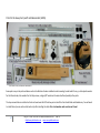
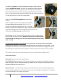
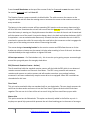
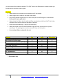
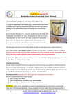
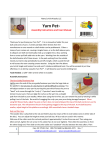
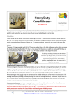
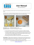
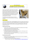
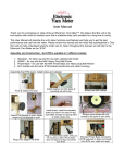
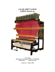
Nancy’s Knit Knacks LLC Heavy Duty Swift & Skeinwinder Assembly Instructions and User Manual Thank you for purchasing our new Heavy Duty Swift and Skeinwinder. As of the Fall 2010, this is our newest addition to our product line. It was designed for use by yarn shops, professionals and other commercial operations, and for all other discriminating fiber artists. First and foremost, it is heavy duty and highly durable. Secondly, it is a competent machine and is able to handle all normal single skein winding operations. Lastly, it is part of an integrated system which consists of metered and motorized options, ball winding systems, and yarn metering equipment. We are confident that you will enjoy using this equipment for many years to come. Tools Needed: Philips #2 Screwdriver, 9/16 wrench/socket (opt: Philips #1 screwdriver for yarn clip) Assembly Instructions You will need to complete the final assembly of the unit since it was not possible to efficiently ship this size unit in a fully assembled state. The benefit of doing this assembly, however, is that you will get to know your new machine and will see just how it is constructed. Plus, when you get it assembled and see it working, you can take special pride in the machine since you built it. Assembly Overview (assembly time: 30 minutes after reading these instructions) The unit is broken down into 3 major groups 1. Base, Socket, and I-Beam 2. Main Shaft, Bearings, Aluminum Arms, and hardware 3. Yarn Guide Posts, Sled Assemblies, Handle, and hardware IMPORTANT - Many of the assemblies are packed in rigid paper bags to protect them as well as the other items in the box during transit. These are labeled and color coded. When proceeding to Step 1 below, carefully remove the contents in each bag including any separate poly bags that may be inside. Keep the contents together. Alternatively, you can keep the parts in the bags until you are ready to use them but arrange the bags in the same manner as the loose parts are in the photo on the next page. NOTE! Be careful in handling the aluminum parts. They have some sharp edges which are accessible until they are capped and/or installed. Step 1 Arrange your parts on the floor or on a large table as pictured on the reverse side of this page. This will help you in grouping parts together. 1 Cary, NC 27518 USA 800-731-5648 Fax 866-445-4371 Rev. 01 [email protected] www.nancysknitknacks.com Parts for the Heavy Duty Swift and Skeinwinder (HDSS) * these items are only included with Skeinwinders Some parts may not be pictured above such as the Rotation Counter and black metal mounting bracket and tilt assy., a white plastic washer for the I Beam knob, lock washers for the Stop screws, a large 5/8” washer on the main shaft and possibly other parts. The stop screws that are installed on the Arms have been left off to allow you to install the Yarn Guide Sleds and Handle assy. You will need to install these (one on each end of each arm) after installing the sleds. Put a lock washer under each screw’s head. 2 Cary, NC 27518 USA 800-731-5648 Fax 866-445-4371 Rev. 01 [email protected] www.nancysknitknacks.com Step 2 Arrange the Base and Socket Assy. on your table top. You have a choice of mounting the 2 clamp bolts from the front edge of the table or you can mount one on the front and one on an adjacent side. If you do it this way, the bolts should be inserted into the slots so that they are the farthest from each other in order to create the best leverage. You can also install the base in any of the other three directions by simply rotating the entire base before installing the clamp bolts. Key Feature: You can adjust the angle of the Socket and I-beam by loosening the 2 knobs and turning the Socket assy. left or right up to 45 degrees. You would do this to better aim the Swift toward your ball winder or other tool/yarn supply. Our unit can be aimed at any location within 360 degrees of the base by means of changing the base’s positioning on the table and through rotating the socket. Always tighten the 2 knobs securely before using the Swift! Step 3 Insert the I-Beam into the Socket Assy. Make sure that the steel T-Nut that is in the tongue of the I-Beam is facing in the same direction as the Brass Logo plate as pictured at right (or on the opposite side of the knob hole). Failure to do this may cause the T-Nut to come out of the unit and void your warranty. Then insert the knob that is in the hardware bag into the back of the Socket Assy. and into the I-Beam tongue. Tighten the knob securely. This locks the 2 units together. Step 4 Next you will install the main shaft into the top of the I-Beam and through the 2 bearing housings. You will install the shaft from the BACK of the I-Beam (the side which is opposite of the Brass Logo plate). The shaft fits snugly through the bearings. You may have to jiggle the shaft and or yellow portion of the front bearing to get the shaft all the way through. Note: you do not need to make any adjustments to the collar on the rear of the shaft. Note: a large 5/8” washer was added to the shaft after this photo was taken. It goes on between the collar at right and the bearings. You will know it is all the way through when the thinner portion of the shaft (3/8” diameter) is completely exposed through the front bearing. Be careful that you do not accidentally bump it back thru the hole when installing other parts. If you do, just repeat the earlier process. 3 Cary, NC 27518 USA 800-731-5648 Fax 866-445-4371 Rev. 01 [email protected] www.nancysknitknacks.com Step 5 Now we will begin to install the aluminum arms and other related components and the Swift will start to take its final form. 1 - The first step is to install the large 2” diameter steel washer onto the shaft. Press against the back of the shaft to keep it from moving out of position when installing all of these parts. Put the smooth part of washer against the bearing. 2- Next we need to slide the Yarn Guide Post Assemblies onto the Aluminum Arms. You will remove the 4 sled assemblies from their protective bags. These bags have a blue sticker on them. You will insert 2 of these onto each arm. First, locate the end of the arm that does not have a black end cap on it. This is the end you will insert the sled into. Also, on Aluminum Arm B, this arm has 2 additional holes drilled into it near the center. These holes are for mounting the Handle. On this arm you will install the sleds and handle support in this sequence: a. Sled #1 – slide the end of the sled that has the wooden dowel closest to the end into the arm as pictured above. Slide this to the other end of the arm. Tighten the knob. b. Handle Mount – slide the small 1” square aluminum slider into the arm. Slide this to the area where the 2 holes are in the arm. Locate the hole closest to the center of the arm and install the ¼-20 x 1.25” machine screw from the back of the arm thru the small 1” square handle mount (this is threaded and the screw must be screwed into it) and into the wooden handle. Make sure you also install the lock washer under the screw head. Tighten the screw firmly and while doing so, position the handle the way you want it so that the yarn clip is where you want it. You will be able to adjust the position after the machine is assembled, also. The handle must be tight but do not over tighten it. c. Sled #2 – slide the 2nd sled into the arm with the end that has the black knob first. d. Once both sleds and handle mount are on the arm, then install the small Stop Screws and lock washers into the hole 4 Cary, NC 27518 USA 800-731-5648 Fax 866-445-4371 Rev. 01 [email protected] www.nancysknitknacks.com on each end from the backside of the arm. Lastly, place the small vinyl cap on the threads of the screw. This screw prevents the sled from going off the end of the arm. e. Important: Install the large black end cap on the end of the arm. Repeat this process on the other arm. Note: Be sure to tighten the knob on each sled so they do not slide around on the arm while you are mounting the arms on the unit. Info: Brakes on the Sleds Each Sled has a built-in brake system that operates to stop the sled from moving and locks it in place on the arm just where you want it to stop. The brake is actuated by turning the black knob on the sled. That presses the brake against the inside of the aluminum. This system leaves no marks on the aluminum and allows the sled to stop at the same location repeatedly without any concern over creating an indentation in the arm. The brake slips onto a pin and remains in place as long as it stays in the arm. If you ever remove the sled, you will have to be careful not to allow the brake to fall out. If it does, simply reinsert it and slide the sled back into the arm. Step 6 – Aluminum Arms Next you will press the 2 large aluminum arms together. You will place arm labeled “B” (see chart on page 2) in your hand and then position Arm “A” into it by pressing them together in the center. Make sure they are fully pressed together. You may have to jiggle them into position since it is a tight fit. Make sure they are properly seated together. Once the arms are pressed together, place them onto the main shaft and up against the large washer. 5 Cary, NC 27518 USA 800-731-5648 Fax 866-445-4371 Rev. 01 [email protected] www.nancysknitknacks.com The shaft has a groove in it which is designed to accept a small metal tab from the 4 Lobe black washer. This is an anti-rotation tab. When you press the 4 lobe washer onto the shaft, make sure this tab fits in the shaft slot. Because the 4 lobes on this washer must fit into the 4 open sections in the arms, you may need to rotate the shaft slightly (from the rear) to get the slot into the right position to install the 4 lobe washer. Install the small 3/8” ID steel washer over the 4 lobe washer. Install the 3/8” Hex nut onto the shaft over the washer. You must tighten the nut securely. Hold one of the arms for leverage when tightening this nut. Use a 9/16” wrench or socket. There should be very little movement (1/32 – 1/16 of an inch) when you tug on the arms after tightening the 3/8” hex nut. Finally, place the black vinyl cap over the hex nut. Test the arms and the bearings now by holding the Handle and spinning the arms to make sure they spin freely. Make sure that no one is in the area who could be hit by the rotating arms. The arms should easily spin and eventually coast to a stop. If for any reason they do not rotate freely, then examine your connections to see if something is rubbing where it shouldn’t. Do not adjust the aluminum collar on the other end of the shaft – it was precisely set at the factory before shipment and this collar location determines the gap on the front. The rotating arms should not touch any wood or other parts other than the parts in this assembly. The 4 arms have very accurate measurements on them to assist you when making a skein. Skeinwinder Owners Skeinwinder owners have a few other features: Yarn Guide for Floor mounted yarn. This yarn guide clamps to your table and should be positioned under the right or left side of the skeinwinder (just below the end of the arm). Experiment with this position to find the correct one for you. Rotation Counter – the Skeinwinder includes our standard rotation counter which we adapted from our row counter product line. It will count rotations. You then multiply the yardage that is measured on the arm settings by the number of rotations. 6 Cary, NC 27518 USA 800-731-5648 Fax 866-445-4371 Rev. 01 [email protected] www.nancysknitknacks.com Press the small blue button at the top of the counter firmly for 3 seconds to reset the count. Hold it for another 3 seconds and it will shut off. The Rotation Counter comes mounted in its black holder. The cable connects the counter to the magnetic switch and will allow the rotating arms to increment the count on the rotation counter on every revolution. The battery in the rotation counter will last upwards of 8-9 months so do not worry about turning it off all of the time. Sometimes the unit will not turn off but this does not mean it is broken. It will dim when the battery is wearing out. Simply disconnect the cable in the back of the unit and tilt stand and pull the counter out of the stand. Unscrew the battery door in the back and replace the battery (AG13 or equivalent – see our website under Resources). Re-attach the door and mount the unit in the tilt stand and re-connect the cable. Be sure to align the small tab on the connector so that it engages the proper part of the mating connector when re-connecting the cable. The custom designed mounting bracket for the rotation counter and ERC allow the user to tilt the bracket up or down to better see the counter’s display when standing in front of the unit. Just loosen the knob and adjust the angle and then re-tighten the knob. 10 foot tape measure – For Skeinwinders only - this is to assist you in getting a super accurate length around the yarn guide posts for strangely sized skeins. ERC (Electronic Rotation Counter – deluxe) The tilt stand that holds the standard rotation counter will also hold the ERC which is our advanced rotation counter based on our Electronic Yarn Meter. The ERC is very powerful and measures rotations and converts to yards or meters and will sound a tone when your yardage has been measured. It will even automatically stop the motor drive is so equipped. More info is available on the website for this item. Floor Stand This unit can be used with either our standard swift or our skeinwinder. The user simply removes the swift from the base socket and inserts it into the Floor Stand. Tighten the knob which locks them together. The user can sit in front of the unit or stand. Using the floor stand frees up your table. Motor drive This option motorizes the Skeinwinder. This option can be easily added in the field to any unit. It employs our special slip system which prevents the unit from breaking yarn in the event of as snag or 7 Cary, NC 27518 USA 800-731-5648 Fax 866-445-4371 Rev. 01 [email protected] www.nancysknitknacks.com jam. A must have for production winders. The 5/16” hole in the I-Beam that is unused is where you would connect the motor mount system. Warnings: Always clamp your unit down to the table with the 2 bolt clamps. Always tighten the 2 knobs on the black rotator plate. Only use the handle to spin the unit or when wind yarn on while using it as a skeinwinder. Never grab the yarn guide posts. Always insert the I-Beam into the table and floor stand sockets with the visible T-Nut facing toward the front (where the brass logo plate is located) . Never lubricate the bearings – they are self lubricating. Always be careful and do not allow someone to get too close to the unit while you are operating it. The spinning arms can hurt someone if they are hit by them. Do not allow children to play with the unit. Contents I-beam with Top Cap Base Socket Assy and Clamps Yarn Guide Post Assy and Sleds (BLUE) Handle Assy (RED with check mark) Yarn Guide Floor (RED)* Hardware Bag Aluminum Arms Rotation Counter and Tilt holder* 10’ Tape Measure* Qty 1 1 4 1 1 1 2 1 1 Swift Y Y Y Y N Y Y N N Skeinwinder Y Y Y Y Y Y Y Y Y * Skeinwinders only 8 Cary, NC 27518 USA 800-731-5648 Fax 866-445-4371 Rev. 01 [email protected] www.nancysknitknacks.com User Manual Swift Lay the skein over the top-most Yarn Guide Post and then around the other three posts. You will have to adjust the Yarn Guide Posts to best fit the skein. When adjusting the Yarn Guide Posts (sleds), loosen the knob about ¾ of a turn so that the sled and its brake system do not “chatter” as you slide the sled in the aluminum arm. Firmly tighten the knob when you get to the spot that you want. Try to have all yarn guides in the same relative position on the 4 arms so that the unit spins evenly and not outof-balance. Be sure to connect one end of your yarn to the clip on the handle so that it will keep it out of the way. The other end will be connected to your ball winder or other device. Always AIM the swift toward the ball winder or other device that is pulling the yarn from the swift. You can do that in multiple ways: adjust the knobs on the base and turn the I-Beam toward the other device or if it is at a steeper angle, then unclamp your bolts on the base and pick up the base and turn it 90 degrees and then re-clamp it to the table. With our design, there is region in the room that you cannot aim the swift toward. Always tighten all knobs and clamps before resuming your winding! When turning the swift’s arms for any reason, always use the handle and not the yarn guide post assemblies. There are two holes for mounting the handle on the aluminum arm. The default position is the inner hole and results in a smaller turning arc. You may move the handle out 1” by mounting it in the second hole. The second hole is less comfortable for some users but has more leverage. The bearings to do not need lubrication. The brake pad in each Sled assembly can be changed if necessary due to excessive use. The bearing assemblies can be changed by the user if necessary. 9 Cary, NC 27518 USA 800-731-5648 Fax 866-445-4371 Rev. 01 [email protected] www.nancysknitknacks.com Skeinwinder Works the same way as the swift. Only run the yarn from the yarn source through the separate Yarn Guide that attaches to the table when feeding yarn from the floor area (never run the yarn sideways through the guide or it will add too much tension). Use the labels on the Arms to determine what size skein you will make. Use the tape measure to measure other size skeins. Rotation Counter – press the blue button at the top of the counter to turn it on. Hold the button down for 3 seconds to get it to reset to zero. Hold it down for an extra 3 seconds to turn it off. Sometimes it will not turn off so let it go in that case. The battery will last 8-9 months even if left on. Clip - Attach the beginning of the skein to the clip on the handle. You can turn the clip in another direction if you loosen the screw with a screwdriver (#1 Philips). Please check our website for an updated manual after you get this unit. Thanks for purchasing our Heavy Duty Swift & Skeinwinder! Specifications and Capacity 80” skein, 2+ Lbs (upper weight limit not determined) Weight: 15 Lbs boxed, 13 + Lbs unboxed Height: 34.75” Width: 31.5” Depth: (table footprint 8.5”) (total 13.75”) Yarn Post Guide Assy’s are 5.5” wide and have vertical containment surfaces on both ends Materials used: Soft Maple hardwood Birch Dowels Aluminum arms and sleds Steel: fasteners and L-Bolts, sheet metal Plastic: Brakes, Yarn Guides on sleds, soft touch (TPE) knobs 10 Cary, NC 27518 USA 800-731-5648 Fax 866-445-4371 Rev. 01 [email protected] www.nancysknitknacks.com