1
Control Unit IN8 USER
MANUAL
FUNCTIONALITIES
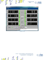
Virtual control panel is structured to make you easy understand implemented control functions.
Picture 4: virtual control panel during acquisition routine.
In the window are present 8 temporal diagram (from CH 1 to CH 8) representing the temporal status evolution of every
input. There are eight lighted controls next to the diagram which indicates status of pin (instantaneous).
The Exit to Windows button alts the program execution and closes the current window.
The Connect button starts the program execution and if the initialization phase complete successfully the Working
connection led light turns on, as shown in Picture 4.
The S/N device ring menu, surrounded by light blue rectangle, allows to select the current device.
The Read Byte indicator, surrounded by blue rectangle, shows the instantaneous inputs status in hexadecimal format.
The Buffer size and Polling Time fields, surrounded by red rectangle, defined the sample array dimension for every input
and the time interval between two consecutive sampling respectively. The sample array dimension can be of 20, 50, 100
or 200 sample, while the polling time can be in the range from 50ms to 1000ms. The set polling time must always be a
multiple of 50 ms, otherwise the program will round it to the nearest value. These values can be modified during program
execution and its consequence will be the update of the graphic time scale.
The software is equipped with a log function. To start or stop this function, use the Log Enable/ Log Disable button,
surrounded in orange in Picture 4. When this feature is enabled, the button will turn on, and you can save into a .txt file
the status of all inputs once a change in their status is detected, recording the date, time and status (in hexadecimal). For
instance:
19
IPSES S.r.l. Via Suor Lazzarotto, 10 - 20020 Cesate (MI) - ITALY
Tel. (+39) 02 39449519 Fax (+39) 02 700403170
http://www.ipses.com e-mail [email protected]