1
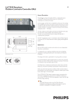
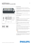
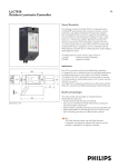
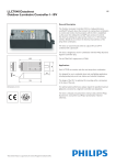
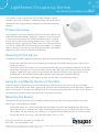
LightSense Occupancy Sensor
User Manual and Installation Instructions
This product is used in conjunction with the SNAP Wireless Lighting
Products from Synapse Wireless. Additional product information can be
downloaded from synapse-wireless.com/industry-iot-solutions/lightingcontrols/
Product Overview
The LightSense Occupancy Sensor (LP201-001) can be installed in any
indoor location where motion detection is needed. The enclosed unit
is a passive infrared sensor that detects movement within a specific
area by sensing the infrared energy emitted from a body as it moves
through the sensor’s field of view. When in use, the system will operate
as a part of a SNAP IEEE 802.15.4 wireless mesh network. This network
allows a sensor to transmit signals to other devices within the network,
eliminating issues caused by localized interference.
Powering On the Device
To power on the SNAP LightSense Occupancy Sensor (LP201-001) take the following steps:
•
Remove the cover on the main unit by gently prying the top and bottom housing apart at the line that
surrounds the unit.
•
Locate the battery holding area and insert the enclosed battery per the directions noted on the plastic
enclosure (positive terminal should be closest to the green LED Light above). After inserting the battery
properly a green LED Light should turn on momentarily above the battery. If the LightSense is being
installed into an active SNAP Lighting mesh network, it will next receive updated software.
•
Put the two plastic covers back together and be sure that they snap completely closed.
Using the LightSense Sensor at Your Site:
Once the sensor is powered on it will start communicating with the other sensors and the Site Controller.
(LP400-001) Please refer to the SNAP Lighting user guide for more information on sensor operation. LightSense
devices will request an update to the configuration and firmware approximately every six hours. If you desire an
immediate configuration update, please remove and reinsert the battery.
Mounting the Sensor
To begin the sensor installation, start by locating where the sensor should be mounted. Keep in mind the
following tips when choosing a location:
•
Position the sensor in an area where users will most likely walk across the detection area. Be sure to
mount the sensor in a direction that avoids unintended activations by users in other areas (For instance,
do not mount the sensor facing into a hallway if it is intended to only detect occupants inside the room).
•
Position the sensor so it faces a solid reference point, such as a wall.
6723 Odyssey Drive // Huntsville, AL 35806 (877)
982-7888 // Synapse-Wireless.com
©2008-2015 Synapse, All Rights Reserved. All Synapse products are patent pending. Synapse, the Synapse logo, SNAP,
and Portal are all registered trademarks of Synapse Wireless, Inc.
116-091514-004-000A
LightSense Occupancy Sensor
•
Do not position the sensor facing windows, fireplaces, air conditioners, area heaters, heating vents, or in
direct sunlight.
•
Position the sensor on a rigid surface, free from vibrations.
•
Mount the sensor at a height of approximately 6-7 feet depending on the height of the users. Keep in mind
that the sensor is aimed on a downward angle.
•
Avoid mounting sensors outdoors or in an area where they will be exposed to moisture or where the
temperature is outside of the normal operating range.
•
If the area of use has pets, try to mount the sensor in an area where the pets will not activate the sensor.
•
Where possible, mount sensors directly into a stud, and if a stud is not available use the enclosed drywall
anchors. We do not recommend the use of double-sided tape to mount sensors unless they are being
mounted on a sensitive surface where the use of screws is not permitted.
•
Walk test the area prior to mounting to ensure that the sensor covers the area appropriately.
After positioning the sensor using the guidelines above, take the following steps to complete successful
installation of the LightSense Occupancy Sensor (LP201-001):
•
Remove the cover on the main unit. To do so, gently pry the top and bottom housing apart at the line
around the unit.
•
Locate the two pre-drilled screw locations on the base plastic unit behind the sensor battery.
•
Mark the location of the holes where they are to be mounted and pre-drill holes in the surface using an
appropriately sized drill bit.
•
Insert the enclosed drywall anchors, when appropriate.
•
Mount the sensor base using the enclosed screws.
•
Replace the sensor battery.
•
Replace the sensor top.
FCC
THIS DEVICE COMPLIES WITH PART 15 OF THE FCC RULES. OPERATION IS SUBJECT TO THE FOLLOWING TWO CONDITIONS:
1.
THIS DEVICE MAY NOT CAUSE HARMFUL INTERFERENCE, AND
2.
THIS DEVICE MUST ACCEPT ANY INTERFERENCE RECEIVED, INCLUDING INTERFERENCE THAT MAY CAUSE UNDESIRED
OPERATION.
THE MANUFACTURER IS NOT RESPONSIBLE FOR ANY RADIO OR TV INTERFERENCE CAUSED BY UNAUTHORIZED
MODIFICATIONS TO THIS EQUIPMENT. SUCH MODIFICATIONS COULD VOID THE USER’S AUTHORITY TO OPERATE THE
EQUIPMENT.