1
User’s Manual
BPI-216 • v1.2 • 07/00 • pg 1
BPI-216 Serial LCD Modules
BPI-216 LCD modules combine a serial interface with a 2-line by 16-character LCD. The combination
receives serial data at 2400 or 9600 baud (switch selectable) and displays it on the LCD.
The unit has two modes: text and instruction. It defaults to text mode; any data received appears on
the screen. Send the string “HELLO” and “HELLO” appears on the LCD. To distinguish text from
instructions (e.g., clear screen, position cursor, etc.), the interface looks for an instruction prefix (ASCII
254). The byte following this prefix is treated as an instruction. After the instruction code, the unit
returns to text mode.
This product replaces BPK-series serial LCD modules, which function identically. The primary difference
is in the physical layout of the circuit board, which has been optimized for 2x16 LCDs. The LCD Serial
®
board (without an LCD; BPK-000) remains available for other applications.
Table of Contents
Location of Connectors and Controls........................................................................................2
Quick Checkout and Contrast Adjustment ................................................................................2
LED Backlight............................................................................................................................2
Setting the Baud Rate ...............................................................................................................3
Hookup for Use .........................................................................................................................3
Basic Operation.........................................................................................................................3
Positioning the Cursor...............................................................................................................4
Off-Screen Memory...................................................................................................................4
Defining Custom Symbols.........................................................................................................5
Program Examples....................................................................................................................7
Dimensions ...............................................................................................................................8
Differences from BPK- series....................................................................................................8
Specifications ............................................................................................................................8
Important Notes on Handling, Installation, Mounting..........................................................8
Disclaimer of Liability
Scott Edwards Electronics, Inc. is not responsible for any special, incidental, or consequential damages resulting
from any breach of warranty, or under any legal theory, including lost profits, downtime, goodwill, damage to or
replacement of equipment or property, and any costs or recovering, reprogramming, or reproducing of data
associated with the use of the hardware or software described herein.
Warranty
Scott Edwards Electronics, Inc. warrants this product against defects in materials and workmanship for a period
of 90 days. If you discover a defect, we will, at our option, repair, replace, or refund the purchase price. Return
the product with a description of the problem. We will return your product or its replacement via standard shipping.
Expedited shipping is available at the customer’s expense.
• Note: Abusing the module, operating it outside specified limits of power or temperature, or attempting to repair
or modify it, voids this warranty. See figure 1 (page 2) and specifications/notes (page 8).
Trademarks and Copyrights
LCD Serial Backpack® is a registered trademark of Scott Edwards Electronics, Inc.; BASIC Stamp® is a registered
trademark of Parallax Inc. All trademarked names referenced herein are the property of their respective holders.
This manual in its entirety is copyright Scott Edwards Electronics, Inc., 1994—2000.
Scott Edwards Electronics, Inc.
1939 S. Frontage Road, Suite F, Sierra Vista, AZ 85635 USA
ph: 520-459-4802 • fax: 520-459-0623 • www.seetron.com
User’s Manual
BPI-216 • v1.2 • 07/00 • pg 2
Location of Connectors and Controls
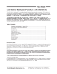
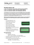
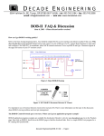
Figure 1 shows the major features and configuration options of the BPI-216 circuit board. Note: The
Backlight switch has no effect on non-backlit models. The model (-L for backlit, -N for non-) is marked
at the lower-left corner of the interface board.
Contrast
Back of LCD
Module
(darker)
+5V
Model
N[x] = non-backlit
L[x] = LED backlit
(backlit shown)
GND
Serial data
1
2
Duplicate +5V and GND
connections (see text)
BPS switch
EXTERNAL Backlight switch
(down = 2400; up = 9600)
BACKLIGHT switch
(see figure 2 for details)
(down = off; up = on)
Do not reverse +5V and GND, even momentarily. Reversed power will destroy the electronics.
Do not exceed 5.5V into +5V. Overvoltage will damage the unit or shorten its life.
Figure 1. Back (interface-side) view of BPI-216.
Quick Checkout and Contrast Adjustment
You can test the unit for proper operation without a computer/serial port. Temporarily connect the
serial input to one of the +5 terminals of J1, then connect power to +5 and GND. The LCD will display
a test message.
The contrast control is usually set fully clockwise at the factory. This setting may be too dark. Use a
small, flat-blade screwdriver to adjust the contrast control.
LED Backlight
On models equipped with an LED backlight (marked L[x] in the lower left corner of the interface board),
you may turn on the backlight by setting the BL switch ON. The backlight will be on whenever power
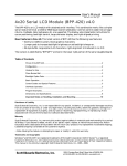
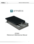
is applied. There is also a pair of solder pads near the backlight switch (see figure 1 above) to allow
you to control the backlight with an external switch or circuit. Figure 2 below shows the wiring of the
backlight and the pads.
Pads on pcb
(close up section of
fig. 1 above)
Figure 2. Connecting
external circuits to
control the backlight.
Equivalent Circuit
Applications
(Built-in BL switch must be OFF)
+5V
LEDs
(Vforward≈ 4V)
1
27Ω
pad 1
1
2
BL
switch
Scott Edwards Electronics, Inc.
pad 2
press-to-light
pushbutton
2
NPN
470–
1k
control with
5V logic (1=ON)
1939 S. Frontage Road, Suite F, Sierra Vista, AZ 85635 USA
ph: 520-459-4802 • fax: 520-459-0623 • www.seetron.com
User’s Manual
BPI-216 • v1.2 • 07/00 • pg 3
Setting the Baud Rate
Set the BPS switch down for 2400 baud; up for 9600. At either rate, the serial characteristics are no
parity, 8 data bits, 1 stop bit. For more information on serial transmission, see the application note:
www.seetron.com/ser_an1.htm.
NOTE: The interface reads the BPS switch only at startup. Change the BPS setting only with the
power off. The Backlight (BL) may be turned on or off at any time.
Hookup for Use
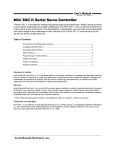
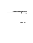
Figure 3 shows how to connect the BPI-216 to PCs and BASIC Stamp computers in order to run the
example programs presented later in this manual. Refer to figure 1 or the markings on the interface
for the locations of +5, GND and SER(ial in).
The 5-pin connector has two extra pins for +5 and GND. These pins are arranged in a pallindrome
layout. If you make a matching 5-pin connector, the connections will always line up properly regardless
of connector orientation. Ready-made wiring harnesses and instructions for making your own hookups
are available from www.seetron.com. If you do not need a removable connector, you may wire-wrap or
solder wires directly to the header posts.
PC Serial (comm) Port
BASIC Stamps
BPI-216
Stamp
SER
DB-9 female
(solder side)
1
2
3
4
5
GND
+5
6
7
8
+5
9
Note: the gray lines are loopback connections that may
be required if the PC software/hardware expects
handshaking. They may be omitted in most cases.
power
supply
GND (Vss)
+5V (Vdd)
I/O pin 0 (P0)
BPI-216
GND
+5
SER
Figure 3. Connecting to PC serial port, BASIC Stamps.
Basic Operation
Once the BPI-216 is properly connected and configured to match the baud rate of the computer/program
that will be talking to it serially, data sent to it will appear on the display. For example, if you send
“Hello” then “Hello” appears on the display. The cursor (printing position) automatically moves from
left to right.
You can also send instructions to the BPI-216. To identify a particular byte as an instruction, precede
it with the instruction prefix character, ASCII 254 (0FE hex, 11111110 binary). The interface treats the
byte immediately after the prefix as an instruction, then automatically returns to data mode.
Example: The clear-screen instruction is ASCII 1. To clear the screen, send <254><1> (where the <>
symbols mean single bytes set to these values, not text as typed from the keyboard). Table 1 lists the
LCD instructions.
Startup Time
When the BPI-216 is first powered up, it requires about 750 milliseconds (ms) to initialize the LCD
and get ready to receive data. Programs should wait about a second after powerup before sending data
to the BPI-216.
Scott Edwards Electronics, Inc.
1939 S. Frontage Road, Suite F, Sierra Vista, AZ 85635 USA
ph: 520-459-4802 • fax: 520-459-0623 • www.seetron.com
User’s Manual
BPI-216 • v1.2 • 07/00 • pg 4
Table 1. LCD Instructions
Instruction/Action
Clear Screen
Scroll display one character left (all lines)
Scroll display one character right (all lines)
Home (move cursor to top/left character position)
Move cursor one character left
Move cursor one character right
Turn on visible underline cursor
Turn on visible blinking-block cursor
Make cursor invisible
Blank the display (without clearing)
Restore the display (with cursor hidden)
Set cursor position (DDRAM address)
Set pointer in character-generator (CG) RAM
Code
1
24
28
2
16
20
14
13
12
8
12
128 + addr
64 + addr
These instructions take more than 1 ms for the LCD to execute. At 9600 bps, either pause
1ms after these instructions or follow them with <254><128> (where <#> means a byte
set to #). At 2400 bps, no pause or extra instruction is required.
Advanced LCD users: These are the actual LCD instruction codes. When the interface receives the instruction prefix, it clears
the register select (RS) bit. The next received byte is written to the LCD with RS low. After writing that byte, it returns RS high
(normal data mode). This means that you can send any valid LCD instruction through the interface. Since the interface intializes
the LCD at startup, you must not send any initialization instructions. If you did not understand the preceding, don’t worry. You
don’t need to know any of this to use this product. The info may be handy to advanced users adapting programs written to drive
the BPI-216 to applications that drive an LCD directly through its parallel interface.
Positioning the Cursor
You can position the cursor anywhere on the screen by sending the proper instruction. Figure 4 shows
the layout of the 2x16 LCD screen with the cursor-positioning instruction for each character location.
Character
LINE 1
LINE 2
0
1
2
3
4
5
6
7
8
9
10
11
12
13
14
15
128 129 130 131 132 133 134 135 136 137 138 139 140 141 142 143
192 193 194 195 196 197 198 199 200 201 202 203 204 205 206 207
To position the cursor, send the instruction-prefix byte, ASCII 254, followed by the set-position
byte value. For example, to move to line 2, character 4, send <254><196>. Note: <#> means
a byte set to the value #. See program examples.
Figure 4. Cursor positioning.
Off-Screen Memory (No Line Wrap)
When you print past the end of a line, the next 24 characters do not show up on the screen. They are
not lost, they are in an off-screen memory area. All alphanumeric LCD modules have 80 bytes of
memory, arranged appropriately for a 2x40 screen. On LCDs with smaller screens (such as this 2x16),
text printed past the end of a visible line goes into memory, but can’t be seen on the screen. Use cursorpositioning instructions to print to a particular location on the display. Or deliberately print in offscreen memory to temporarily hide text, then send scroll-left instructions to reveal it.
Scott Edwards Electronics, Inc.
1939 S. Frontage Road, Suite F, Sierra Vista, AZ 85635 USA
ph: 520-459-4802 • fax: 520-459-0623 • www.seetron.com
User’s Manual
BPI-216 • v1.2 • 07/00 • pg 5
Defining Custom Symbols
Most of the LCD characters (figure 6) cannot be changed because they are stored in ROM. However,
the first eight symbols, corresponding to ASCII 0 through 7, are stored in RAM. By writing new values
to the character-generator (CG) RAM, you can alter these characters. Changing a symbol is easy; just
point to the beginning of the symbol’s RAM location, then write eight bytes whose bits form the desired
pattern. Then position the cursor onto the screen. See figure 5.
Manipulating custom characters allows you to create special effects, like simple animations. See serial
display application notes at www.seetron.com for examples and a handy visual character editor.
Symbol Locations
Byte Values
bit 0
bit 1
bit 2
bit 3
bit 4
Bitmap Layout
byte 0
binary
xxx00000
decimal
0
byte 1
xxx00100
4
byte 2
xxx00010
2
byte 3
xxx11111
31
byte 4
xxx00010
2
byte 5
xxx00100
4
byte 6
xxx00000
0
byte 7
xxx00000
0
ASCII
Code
Base
Address
0
1
2
3
4
5
6
7
64
72
80
88
96
104
112
120
Example: Loading the Symbol
To load the arrow shown at left to symbol 3,
a program would send the following bytes to
the LCD:
<254><88>
' Point to symbol 3
<0><4><2><31>
<2><4><0><0>
' Send the bit
' pattern
<254><128>
' Move cursor back
' to the screen
<#> means a byte set to the value #.
See the program examples.
Figure 5. Defining custom symbols.
0
32
40
48
56
64
72
80
88
96
104 112 120 160 168 176 184 192 200 208 216 224 232 240 248
0
1
2
3
4
5
6
7
NOTE: Custom characters occupy ASCII 0—7
Backpack loads patterns shown at startup.
ASCII 8—31 repeat the custom characters
ASCII 128–160 are blanks
To find the ASCII code for a given character, add the row and column numbers.
For example, capital D is in the column marked 64 in row 4, so its ASCII code is
68. Use the reverse procedure to determine the symbol for a given code. For
example, ASCII code 244 produces the symbol Ω, found at colum 240, row 4.
Figure 6. LCD character set.
Scott Edwards Electronics, Inc.
1939 S. Frontage Road, Suite F, Sierra Vista, AZ 85635 USA
ph: 520-459-4802 • fax: 520-459-0623 • www.seetron.com
User’s Manual
BPI-216 • v1.2 • 07/00 • pg 6
Program Examples
Any computer/programming language that can produce serial output (2400 or 9600 bps, N81) can talk
to the BPI-216. The examples here are in BASIC, chosen because of its popularity and readability.
Don’t be put off by the size of the programs—they are mostly comments.
See www.seetron.com for Windows® programming examples and an easy-to-use DLL that works well
with Visual BASIC®.
'
'
'
'
'
Program: BPKDEMO.BAS
This program demonstrates fundamental techniques of driving
BPI-216 serial LCDs in BASIC (compatible with QBASIC, Quick BASIC,
First BASIC, and Power BASIC). First BASIC, an excellent shareware
compiler, is available from www.powerbasic.com.
' Start by defining some useful constants for the Backpack
I = 254
' Instruction prefix value.
CLR = 1
' LCD clear-screen instruction.
LINE1 = 128
' Address of first character of 1st line.
LINE2 = 192
' Address of first character of 2nd line.
' Open the serial port (com1) for output at 9600 baud. Make sure BPS
' is also set for 9600. Turn off all handshaking (CD, CS, DS) by
' setting to zero (0).
OPEN "COM1:9600,N,8,1,CD0,CS0,DS0" FOR OUTPUT AS #1
' Once the port is open, we can print to it. Start by clearing the screen
' in case there's text left from a previous run of this program. Note that
' at 9600 baud, you need a delay after clearing the screen. To create a
' delay, you can use a timing instruction such as First/Power BASIC's
' DELAY or QBASIC's SLEEP, or you can send an unnecessary instruction,
' such as <254><128>. That sequence moves the cursor to the beginning of
' line 1, which is where it already is, thanks to clear-screen.
PRINT #1, CHR$(I); CHR$(CLR);
' Send <254><1> to clear screen.
PRINT #1, CHR$(I); CHR$(LINE1); ' Time delay (for 9600 baud).
' Now print some text. PRINT statements should end with ; to
' prevent unnecessary carriage return/line feeds (which the Backpack
' doesn't understand, and displays as junk characters).
PRINT #1, "Hello world!";
Quickie Program
Want fast results? All you
need are these two lines
of code. The first opens
the serial port for output;
the second ‘prints’ text to
it.Type and run these lines
in QBASIC or Power
BASIC and “Hello World!”
appears on the display.
' Positioning the cursor requires sending the instruction prefix (ASCII
' 254, which we've assigned the name "I") followed by an address. We've
' assigned names to ASCII 128 (1st character of line 1) and 192 (1st
' character of line 2). We'll position the cursor to the start of
' line 2 and print some more.
PRINT #1, CHR$(I); CHR$(LINE2); "press return";
' Wait for a keypress (at PC) before continuing.
CLS : INPUT "PRESS RETURN TO CONTINUE", X$
' Now we'll simulate a common application by printing a label on the
' screen, then updating some data by positioning the cursor. Each
' time you press return on the PC, the program will add 1 to the
' count and update the value on the screen. Notice that to position
' the cursor at character 6 of line 1, we give the position value of
' LINE1 + 6. This is easier to read than 134, which is the address of
' line 1, character 6. Also note that we print several spaces after
' the number. It's not needed here, but in programs in which a number
' could be _lower_ than the previously displayed value, the spaces
' would erase any leftover digits.
PRINT #1, CHR$(I); CHR$(CLR); CHR$(I); CHR$(LINE1);
PRINT #1, "Count: "; CHR$(I); CHR$(LINE2); "press return";
theCount = 0
Again:
PRINT #1, CHR$(I); CHR$(LINE1 + 6); theCount; "
";
INPUT "ENTER TO CONTINUE, Q-ENTER TO QUIT ", X$
IF UCASE$(X$) = "Q" THEN END
theCount = theCount + 1
GOTO Again
Scott Edwards Electronics, Inc.
1939 S. Frontage Road, Suite F, Sierra Vista, AZ 85635 USA
ph: 520-459-4802 • fax: 520-459-0623 • www.seetron.com
User’s Manual
BPI-216 • v1.2 • 07/00 • pg 7
'
'
'
'
'
Program: BPKDEMS1.BAS
This program demonstrates fundamental techniques of driving
BPI-216 serial LCDs in BASIC from the BASIC Stamp I. It assumes
that the BPI-216 is connected to I/O pin 0 of the Stamp, and
that it is set for 2400 bps.
' Start by defining some useful
SYMBOL I
=
254
'
SYMBOL CLR
=
1
'
SYMBOL LINE2
=
192
'
SYMBOL L1_C7
=
135
'
constants for the BPI-216.
Instruction prefix value.
LCD clear-screen instruction.
Address of 1st char of 2nd line.
Address of line 1, character 7.
' Now clear the screen in case there's text left from a previous
' run of the program. Note that there's a 1-second PAUSE prior to
' sending any data to the Backpack. This gives the unit plenty
' of time to initialize the LCD after power up.
pause 1000
serout 0,n2400,(I,CLR)
' Clear the LCD screen.
serout 0,n2400,("Hello World!")
' Print message.
' Positioning the cursor requires sending the instruction prefix (ASCII
' 254, assigned the symbol "I") followed by an address.
serout 0,n2400,(I,LINE2,"..line 2") ' Move to line 2 and print.
' Now we'll simulate a common application by printing a label on the
' screen and updating some data by positioning the cursor.
pause 2000
' Wait 2 secs.
serout 0,n2400,(I,CLR)
' Clear the LCD screen.
serout 0,n2400,("Count:")
' Print the label.
Again:
serout 0,n2400,(I,L1_C7)
' Move to line 1, character 7.
serout 0,n2400,(#b2," ")
' Print value of b2 followed by 2 spaces.
b2 = b2+1
' Increment b2.
pause 200
' Slow the loop down.
goto Again
' Repeat endlessly.
'
'
'
'
'
Quickie Program
Type and run just this line
in PBASIC 1 and “Hello
World!” appears on the
display.
Program: BPKDEMS2.BS2
This program demonstrates fundamental techniques of driving
BPI-216 serial LCDs in BASIC from the BASIC Stamp II. It assumes
that the BPI-216 is connected to I/O pin P0 of the Stamp, and
that it is set for 9600 bps.
' Start by defining some useful constants for the Backpack.
N9600 con
$4054 ' Baudmode-9600 bps inverted. Use $40F0 for BS2-SX.
I
con
254
' Instruction prefix value.
CLR
con
1
' LCD clear-screen instruction.
LINE2 con
192
' Address of 1st char of 2nd line.
L1_C7 con
135
' Address of line 1, character 7.
' Now clear the screen in case there's text left from a previous
' run of the program. Note that there's a 1-second PAUSE prior to
' sending any data to the Backpack. This gives the Backpack plenty
' of time to initialize the LCD after power up.
pause 1000
serout 0,n9600,[I,CLR]
' Clear the LCD screen.
pause 1
serout 0,n9600,["Hello World!"]
' Print message.
Quickie Program
Type and run just these
lines in PBASIC 2 and
“Hello World!” appears on
the display.
' Positioning the cursor requires sending the instruction prefix (ASCII
' 254, assigned the symbol "I") followed by an address.
serout 0,n9600,[I,LINE2,"..line 2"] ' Move to line 2 and print.
' Now we'll simulate a common application by printing a label on the
' screen and updating some data by positioning the cursor.
pause 2000
' Wait 2 secs.
serout 0,n9600,[I,CLR]
' Clear the LCD screen.
pause 1
serout 0,n9600,["Count:"]
' Print the label.
Again:
serout 0,n9600,[I,L1_C7]
' Move to line 1, character 7.
serout 0,n9600,[DEC b2," "]
' Print value of b2 followed by 2 spaces.
b2 = b2+1
' Increment b2.
pause 200
' Slow the loop down.
goto Again
' Repeat endlessly.
Scott Edwards Electronics, Inc.
1939 S. Frontage Road, Suite F, Sierra Vista, AZ 85635 USA
ph: 520-459-4802 • fax: 520-459-0623 • www.seetron.com
User’s Manual
BPI-216 • v1.2 • 07/00 • pg 8
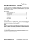
Dimensions
The drawing below gives the primary dimensions of the 2x16 LCDs sold with our BPI-216N and BPI216L products. Three LCD manufacturers are listed, Truly, Data Vision (DV), and Powertip (PT), since
we have at times used LCDs from each of these companies. Powertip is our primary supplier.
A
B
C
D
E
F
G
H
I
J
K
L
-
y offset pcb edge to hole ctr
y pcb height
y hole spacing
y screen opening
y character size
x character size
x offset pcb edge to hole ctr
x screen frame
x screen opening
x hole spacing
x pcb width
y frame height
mounting hole diameter
frame depth, non-backlit
frame depth, LED-backlit
Truly
DV
PT
2.50
36.00
31.00
13.80
4.35
2.95
2.50
73.70
64.50
75.00
80.00
24.80
2.50
5.00
8.50
2.50
36.00
31.00
16.10
4.89
2.78
2.50
71.20
62.50
75.00
80.00
26.20
2.50
4.70
9.40
2.50
36.00
31.00
16.20
5.94
2.95
3.55
71.00
66.00
75.00
80.00
25.00
2.50
5.00
8.50
H
A
B
C
D
E
L
F
I
J
K
G
• All dimensions in mm.
• Worst-case tolerance for any dimension is ±0.50mm.
• Maximum depth (from front of screen frame to tips of interface header posts) is 26mm.
• Dimensions based on information provided by manufacturers—subject to change without notice.
Figure 7. Physical dimensions.
Important Notes on Handling, Installation, and Mounting
LCDs are precision-made devices that should last a lifetime of normal use. They are vulnerable to
damage from mishandling, however. Our warranty excludes damage from abuse, so it is very important
that you handle and mount your LCD with care. Here are some tips:
• Handle in a static-safe manner
• Do not use glue, epoxy, or paint on this unit
• Do not drop or strike
• Protect from water, solvents, oils
• Do not attempt to disassemble, repair, or modify
• Do not bend, warp, or stress
• Do not drill, cut, notch, grind, etc.
• Install behind a protective transparent window
• Mount with machine screws in corner holes
• Protect from strong electrical fields, ESD
• Do not attempt to enlarge mounting holes
• Protect from reverse-power hookup
Differences from BPK-series Devices, Basic Specifications
BPI-216N/L is functionally identical to the previous
BPK-216N/L series. The main differences are in the
circuit-board layout, which in the BPI-216 has been
tailored specifically for 2x16 LCDs. The BPK-series is
a more generic layout, suitable for installation on
many LCD types. BPI-216N/L replaces BPK-216N/L,
but the BPK-000 (interface without LCD) is still
available. The table at right sums up the differences
between the two.
Table 3. Basic
Specifications
Feature
BPK
Interface board sold w/out LCD
YES
no
Backlight switch/series resistor
no
YES
LINES switch for 1-line LCDs
BPI
YES
no
no
YES
Low, < 1mA current draw (interface)
YES
YES
LCD-based serial protocol
YES
YES
Reversible 5-pin power/signal header
YES
YES
Sold with LCD installed
Power requirements (backlight off) ........................4.8 to 5.2 Vdc @ 3 mA
Power requirements (backlight on) ......................4.8 to 5.2 Vdc @ 40 mA
User connector......................................Five 0.025" pins on 0.10" centers
Connector pinout ....................................................+5 GND SER GND +5
Serial input...............RS-232, or inverted TTL/CMOS, 2400 or 9600, N81
Operating temperature......................................0° to 50°C (32° to 122°F)
Storage temperature ......................................–10° to 60°C (14° to 140°F)
LCD type ..................................................Supertwist (STN), yellow-green
Optimum viewing direction...........................................................6 o'clock
Scott Edwards Electronics, Inc.
1939 S. Frontage Road, Suite F, Sierra Vista, AZ 85635 USA
ph: 520-459-4802 • fax: 520-459-0623 • www.seetron.com